| GENX-1B CLEANING,INSPECTION,AND REPAIR MANUAL | Dated: 04/30/2014 | |
| CIR 72-31-41 , CLEANING 001 | ||
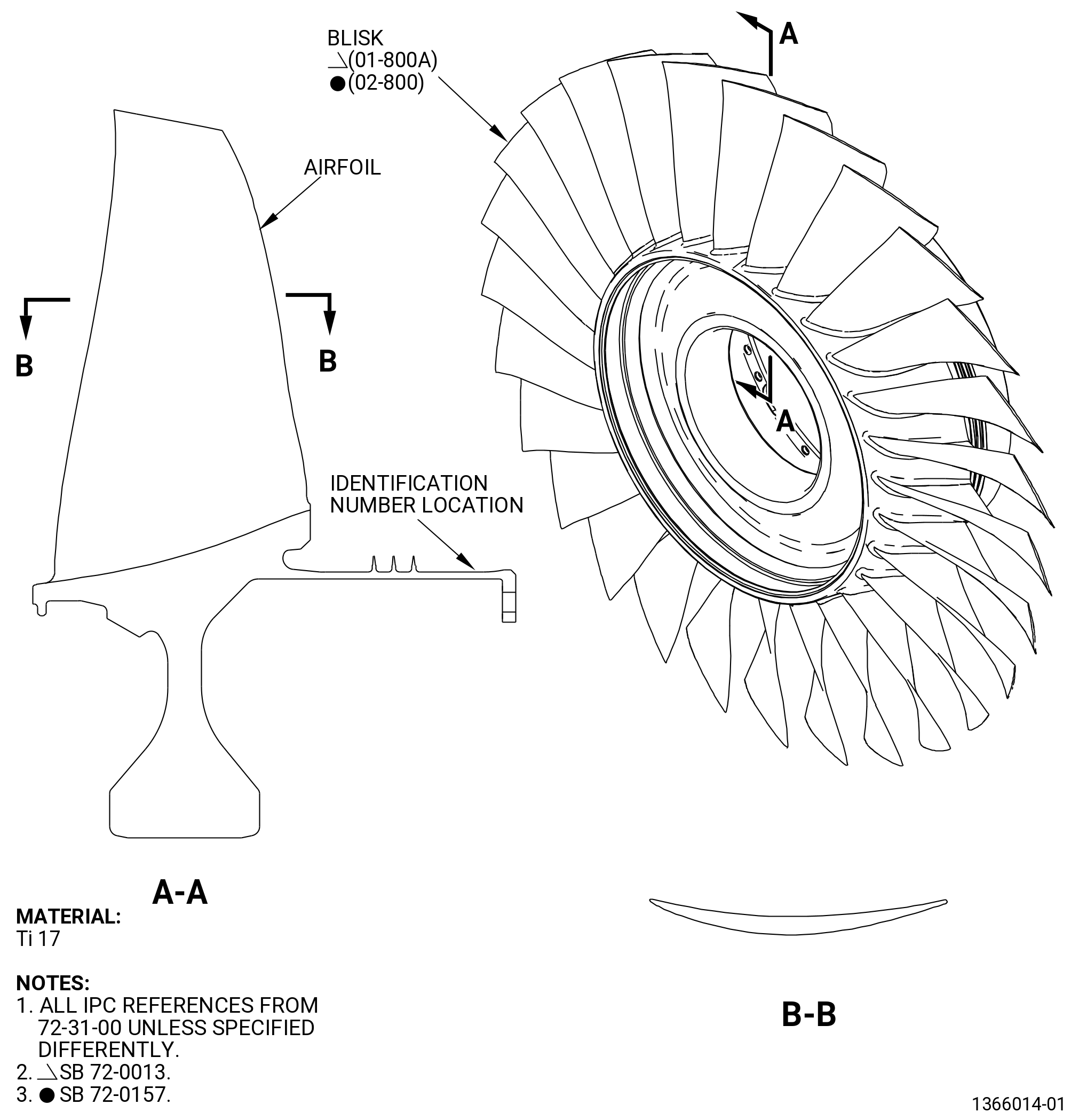
| HPC STAGE 1 BLISK - CLEANING | ||
| GENX-1B CLEANING,INSPECTION,AND REPAIR MANUAL | Dated: 04/30/2014 | |
| CIR 72-31-41 , CLEANING 001 | ||
| HPC STAGE 1 BLISK - CLEANING | ||
| * * * FOR ALL |
| TASK 72-31-41-100-801 |
| 1 . | General. |
| A. | This procedure gives instructions to clean the HPC stage 1 blisk (blisk). Refer to Figure 601 and Figure 601A. |
| • |
|
| • |
|
| • |
|
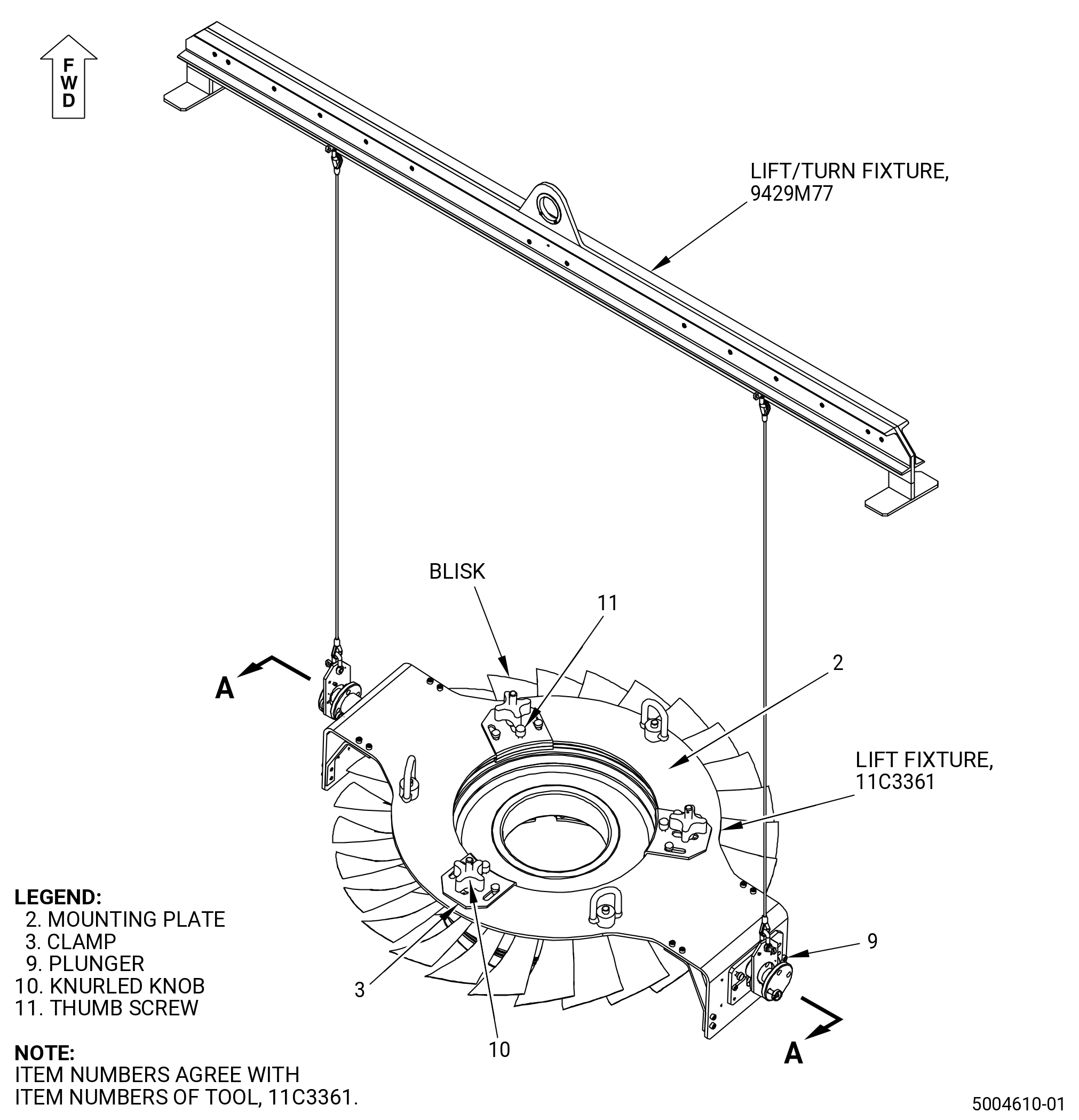
| B. | Use the 11C3361 lift fixture to position, lift, or turn the blisk in the working area. Refer to Subtask 72-31-41-420-001 (paragraph 4.) for instructions about installation and removal of the tool. |
| 2 . | Tools, Equipment, and Materials. |
| NOTE: |
|
| A. | Tools and Equipment. |
| (1) | Special Tools. |
|
| (2) | Standard Tools and Equipment. None. |
| (3) | Locally Manufactured Tools. None. |
| B. | Consumable Materials. |
|
| C. | Referenced Procedures. |
| D. | Expendable Parts. None. |
| 3 . | General Cleaning. |
| Subtask 72-31-41-160-001 |
| WARNING: |
|
| A. | Alternative Procedures Available. Steam clean the blisk. Refer to TASK 70-21-03-160-001 (CLEANING METHOD 3 - STEAM CLEANING). |
| Subtask 72-31-41-110-001 |
| A.A. | Alternative Procedure. Alkaline clean the blisk. Refer to TASK 70-21-09-110-007 (CLEANING METHOD 9 - LIGHT-DUTY ALKALINE CLEANING OF TITANIUM ALLOYS). |
| Subtask 72-31-41-120-001 |
| A.B. | Alternative Procedure. Dry abrasive blast clean the blisk with C04-116 Rice Hulls. Refer to TASK 70-21-04-120-B01 (Dry Abrasive Blast Cleaning Method 4B). |
| Subtask 72-31-41-120-002 |
| A.C. | Alternative Procedure. Dry abrasive blast clean the blisk with C04-153 Plastic Abrasive. Refer to TASK 70-21-04-120-E01 (DRY ABRASIVE BLAST CLEANING METHOD 4E). |
| Subtask 72-31-41-110-002 |
| A.D. | Alternative Procedure. Light duty aqueous clean the blisk. Refer to TASK 70-21-22-110-042 (CLEANING METHOD 22 - LIGHT DUTY AQUEOUS CLEANING (METHOD 1)). |
| Subtask 72-31-41-120-004 |
| A.E. | Alternative Procedure. Wet abrasive blast clean the blisk with 500 grit aluminum oxide. Refer to TASK 70-21-05-120-B02 (WET ABRASIVE BLAST CLEANING METHOD 5B) and TASK 70-00-99-801-054 (S1054 - WET ABRASIVE BLASTING - ALUMINUM OXIDE 500 GRIT). |
| 4 . | Tool Installation and Removal. |
| Subtask 72-31-41-420-001 |
| A. | Install the 11C3361 lift fixture. Refer to Figure 602 and do as follows: |
| (1) | Move the clamp (item 3) in, before the mounting plate (item 2) is installed on the blisk. |
| (2) | Install the mounting plate (item 2) on the forward flange of the blisk. |
| WARNING: |
|
| (3) | Move the clamp (item 3) out to lock on the lip of the blisk flange in the groove of the clamp (item 3). |
| (4) | Manually turn the thumb screw (item 11) to adjust it until there is no clearance between the clamp (item 3) jaw and the blisk flange. |
| (5) | Make sure that the thumb screw (item 11) is correctly installed in the pocket of the mounting plate (item 2). |
| (6) | Turn the knurled knob (item 10) to attach the clamp (item 3). |
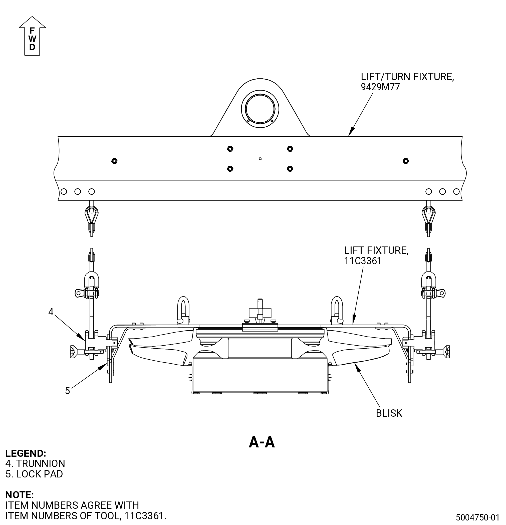
| (7) | Set the lock pad (item 5) on the mounting plate (item 2) as follows: |
| (a) | Move the trunnion (item 4) to the top position in the slot of the mounting plate (item 2). |
| (b) | Lock the trunnion (item 4) with the lock pad (item 5) in the top position. |
| (c) | Release the plunger (item 9) to move the lock pad (item 5). |
| (d) | Engage the plunger (item 9) in the related mounting plate (item 2) hole to keep the lock pad (item 5) in position. |
| (8) | Use the 9429M77 lift/turn fixture to move the 11C3361 lift fixture. |
| Subtask 72-31-41-020-001 |
| B. | Remove the 11C3361 lift fixture. Refer to Figure 602 and do as follows: |
| (1) | Loosen the knurled knob (item 10) to release the clamp (item 3). |
| (2) | Loosen the thumb screw (item 11) until is released from the pocket of the mounting plate (item 2). |
| (3) | Move the clamp (item 3) in to release the lip of the blisk flange out of the groove of the clamp (item 3). |
| (4) | Remove the mounting plate (item 2) from the blisk. |