| GENX-1B CLEANING,INSPECTION,AND REPAIR MANUAL | Dated: 04/03/2024 | |
| CIR 72-31-41 , REPAIR 001 | ||
| HIGH PRESSURE COMPRESSOR STAGE 1 BLISK - REPAIR - AIRFOIL BLEND REPAIR | ||
| GENX-1B CLEANING,INSPECTION,AND REPAIR MANUAL | Dated: 04/03/2024 | |
| CIR 72-31-41 , REPAIR 001 | ||
| HIGH PRESSURE COMPRESSOR STAGE 1 BLISK - REPAIR - AIRFOIL BLEND REPAIR | ||
| * * * FOR ALL |
| TASK 72-31-41-300-801 |
| 1 . | Airfoil Blend Repair. |
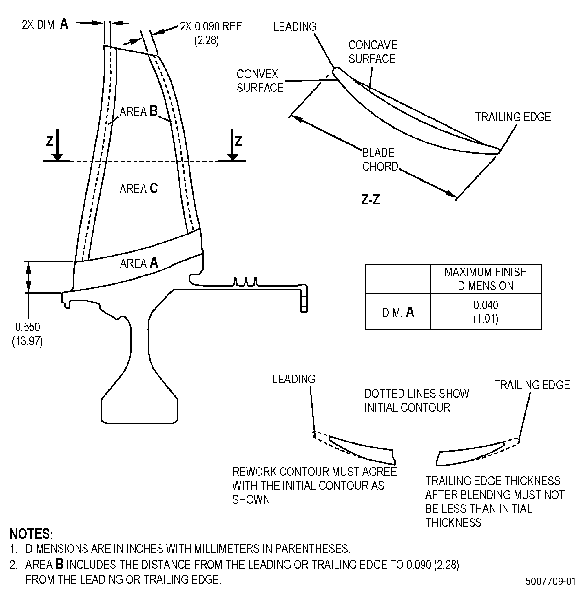
| A. | This procedure gives instructions to repair the high pressure compressor rotor stage 1 blisk (blisk) airfoils by blending the damaged areas. Refer to Figure 901. |
| B. | The following maximum repairable limits apply to this repair: |
| NOTE: |
|
| (5) | Visual Inspection. |
| (c) | Do an inspection of area B (leading and trailing edges) on the blisk blade for: |
| 1 | Nicks: |
| Maximum repairable limit: |
|
| 2 | Dents and pits: |
| Maximum repairable limit: |
|
| 3 | Scratches and gouges: |
| Maximum repairable limit: |
|
| 4 | Deposits: |
| Maximum repairable limit: |
|
| 5 | Metal splatter deposits: |
| Maximum repairable limit: |
|
| 9 | Tears: |
| Maximum repairable limit: |
|
| (h) | Do an inspection of the tip corners of the blisk for: |
| 3 | All other damage: |
| Maximum repairable limit: |
|
| C. | The subsequent table gives a list of the part numbers that are applicable to this procedure. All part numbers are applicable to all paragraphs unless specified differently. |
|
|||||||||||||||||||||||
| D. | Proprietary/Complex Process Statement. |
| (1) | None. |
| 2 . | Tools, Equipment, and Materials. |
| NOTE: |
|
| A. | Tools and Equipment. |
| (1) | Special Tools. None. |
| (2) | Standard Tools and Equipment. |
|
| (3) | Locally Manufactured Tools. None. |
| B. | Consumable Materials. |
| C. | Referenced Procedures. |
|
| D. | Expendable Parts. None. |
| E. | SPD Information. |
| (1) | Spares Supplied. None. |
| (2) | Protected Spares. None. |
| (3) | Locally Manufactured Spares. None. |
| F. | Special Solutions. None. |
| G. | Test Specimens. None. |
| 3 . | Dimensional Information. |
| Subtask 72-31-41-220-087 |
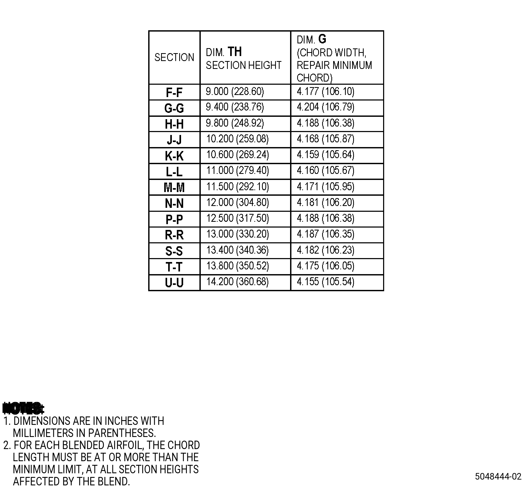
| A. | Refer to Figure 901 and Figure 902 for specified dimensions and locations. |
| NOTE: |
|
| NOTE: |
|
| NOTE: |
|
| 4 . | Setup Information. |
| None. |
| 5 . | Procedure. |
| Subtask 72-31-41-160-009 |
| CAUTION: |
|
| A. | If necessary, clean the blisk. Refer to TASK 72-31-41-100-801 (72-31-41, CLEANING 001). |
| Subtask 72-31-41-350-007 |
| WARNING: |
|
| CAUTION: |
|
| CAUTION: |
|
| CAUTION: |
|
| CAUTION: |
|
| B. | Blend the blisk damaged areas on the leading and trailing edges, area B. Refer to TASK 70-42-00-350-002 (BLENDING AND REMOVAL OF HIGH METAL PROCEDURES), Figure 901, Figure 902, Figure 904 and as follows: |
| (1) | Blending is not permitted on area A and area C of the blisk. |
| WARNING: |
|
| (2) | Use a fine C10-010 abrasive cloth or an abrasive stone as follows: |
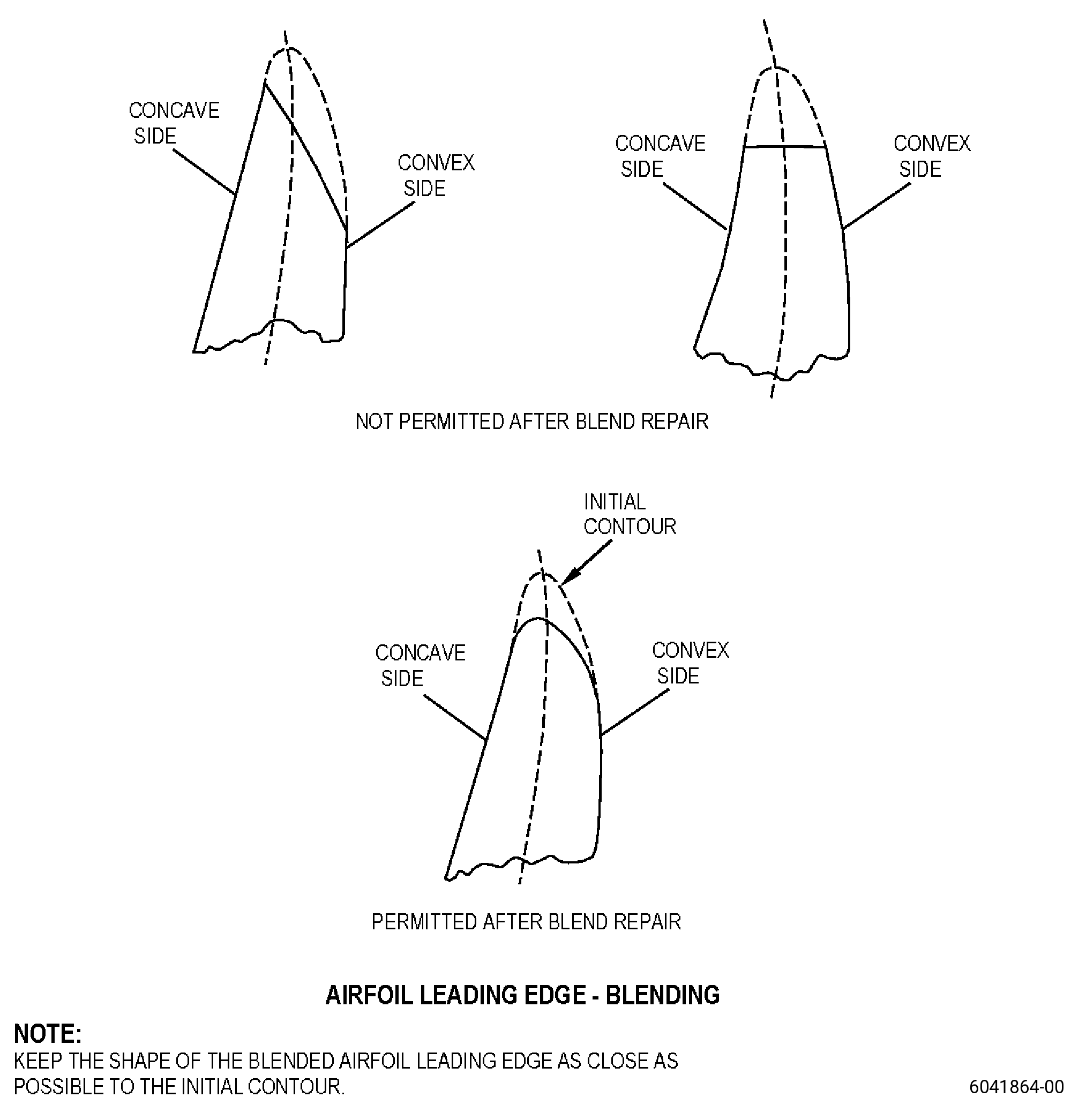
| (a) | Blend in longitudinal direction only (parallel to the blade length). |
| NOTE: |
|
| (b) | Make sure that the surface finish after the blending procedure is equivalent to or better than the initial surface finish. |
| (3) | For the tears damage, blend 1.25 times the damage depth to fully remove the damage. |
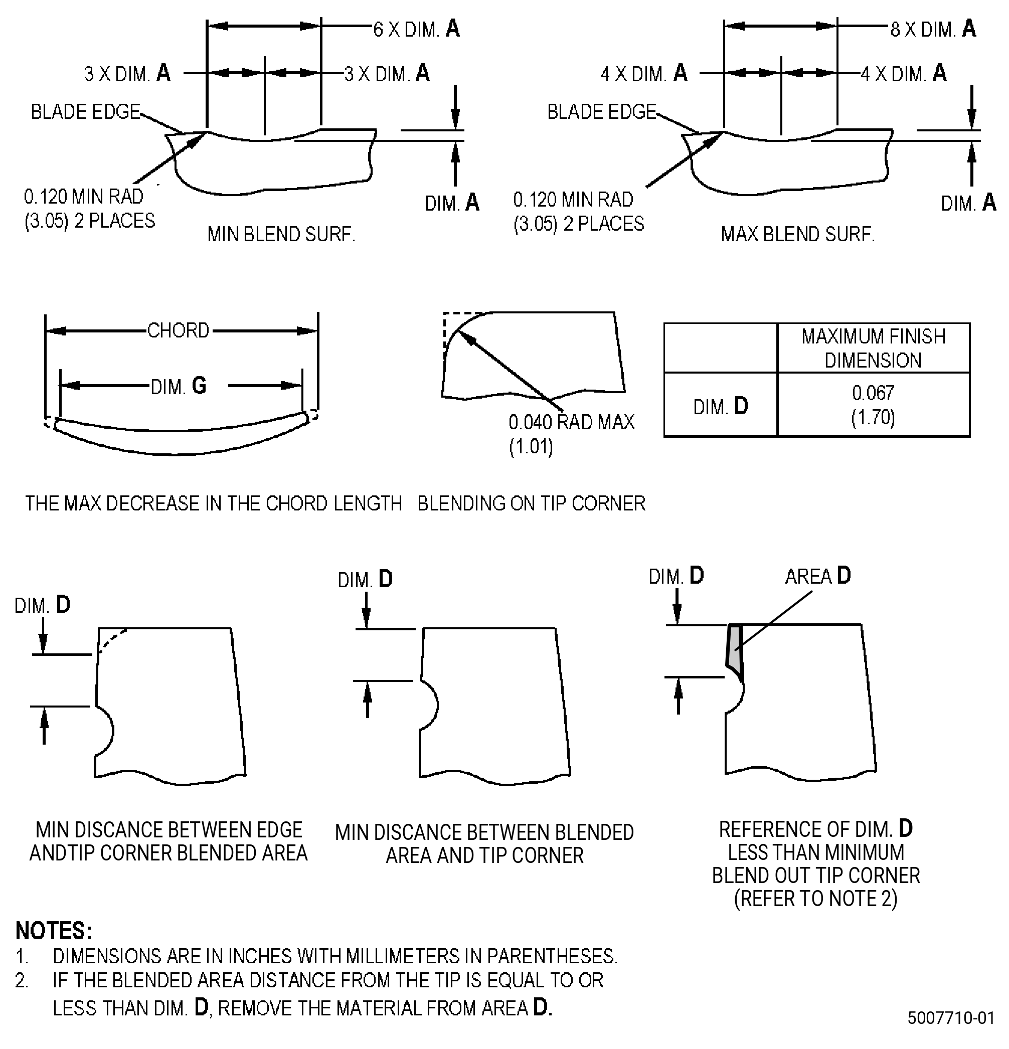
| (4) | The blend length must be a minimum of six times the depth of the damage and maximum eight times the depth. |
| (5) | The blended contour of the blisk repair area must be the same as the contour of the adjacent non-blended areas. |
| (6) | The trailing edge thickness in the blisk repair area must not be less than the thickness of the adjacent non-blended trailing edge. |
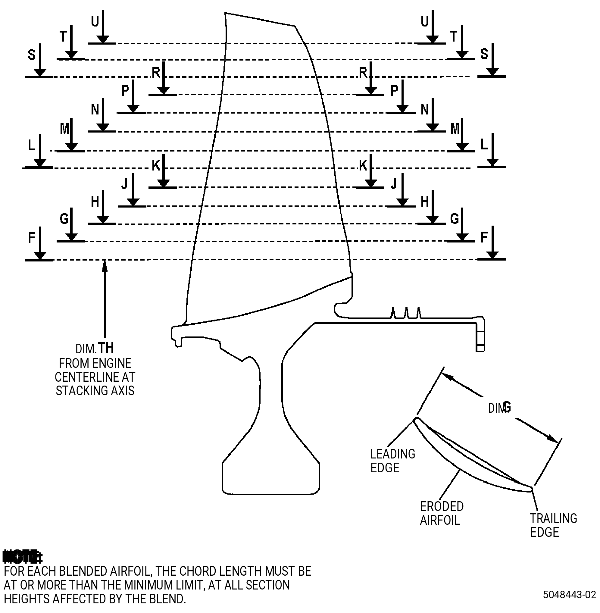
| (7) | The chord length in the repaired section of the blisk airfoil must not be less than the minimum dimension G after the repair. |
| NOTE: |
|
| (8) | If the blend location, measured from the airfoil tip, is equal to or less than dimension D, blend area D. Refer to Figure 902 and do as follows: |
| (a) | Remove the unwanted material in area D. |
| (b) | Keep blend depth to the same depth as the initial blend depth. |
| (9) | The maximum number of permitted blends is dependent on blend depths and must be within requirements of Figure 904. These requirements must be read as follows: |
| (a) | Count the total number of blends necessary between 0.025-0.040 inch (0.64-1.01 mm) in depth (if there are blends done before, include them) and find this number in column C, and as follows: |
| 1 | For blends from previous repair only, it is permitted to have a blend ratio that is greater than 8 to 1. It is not permitted to create new blends greater than 8 to 1. |
| (b) | Do a check of the same row in column D that agree with the maximum permitted number of blends less than 0.025 inch (0.63 mm) in depth. |
| NOTE: |
|
| (c) | The total blend count must include all blends done before and the number cannot be more than the given in column C and column D. |
| (d) | You can blend one airfoil, if a minimum of one adjacent airfoil before and one adjacent airfoil after are not blended. |
| (e) | You can blend a set of airfoils (it means two, three, or four consecutive airfoils) if a minimum of three adjacent airfoils before and three adjacent airfoils after are not blended. |
| (f) | You cannot blend more than seven airfoils on the blisk. This includes the airfoils blended before. |
| Subtask 72-31-41-110-003 |
| C. | Etch the blisk repair areas. Refer to TASK 70-24-00-110-033 (ETCHING PROCEDURES FOR FLUORESCENT-PENETRANT INSPECTION), TASK 70-24-01-110-034 (SWAB ETCHING PROCEDURE), and as follows: |
| (1) | Use Class B etchant. |
| Subtask 72-31-41-230-007 |
| D. | Do an inspection of the blisk airfoil repair areas. Refer to TASK 70-32-00-200-002 (INDIRECT INSPECTION METHODS), TASK 70-32-02-230-001 (FLUORESCENT PENETRANT INSPECTION), and as follows: |
| (1) | Use Class G penetrant. |
| (2) | Indications are not permitted at edges, in fillets, or 0.100 inch (2.54 mm) of the edges of the airfoil. |
| (3) | Deleted. |
| (4) | Indications 0.015 inch (0.38 mm) or less are permitted. |
| (5) | Linear indications are not permitted. |
| NOTE: |
|
| Subtask 72-31-41-380-001 |
| E. | Alternative Procedure Available. Peen the blisk area CA. Refer to TASK 70-47-01-380-016 (SHOTPEENING), Figure 903 and as follows: |
| (1) | It is necessary to peen at the same time on the two sides of the airfoil. |
| (2) | Apply C10-021 plastic tape to the blisk areas that you will not peen. |
| (3) | Use C04-286 S110 cast steel shot at an intensity of 0.006-0.012N. |
| (4) | Make sure that you make the intensity verification in the blisk repair area with a scrap part or simulative fixture. |
| (5) | A minimum coverage of 100 percent is necessary. |
| (6) | Remove the plastic tape from the blisk. |
| Subtask 72-31-41-380-004 |
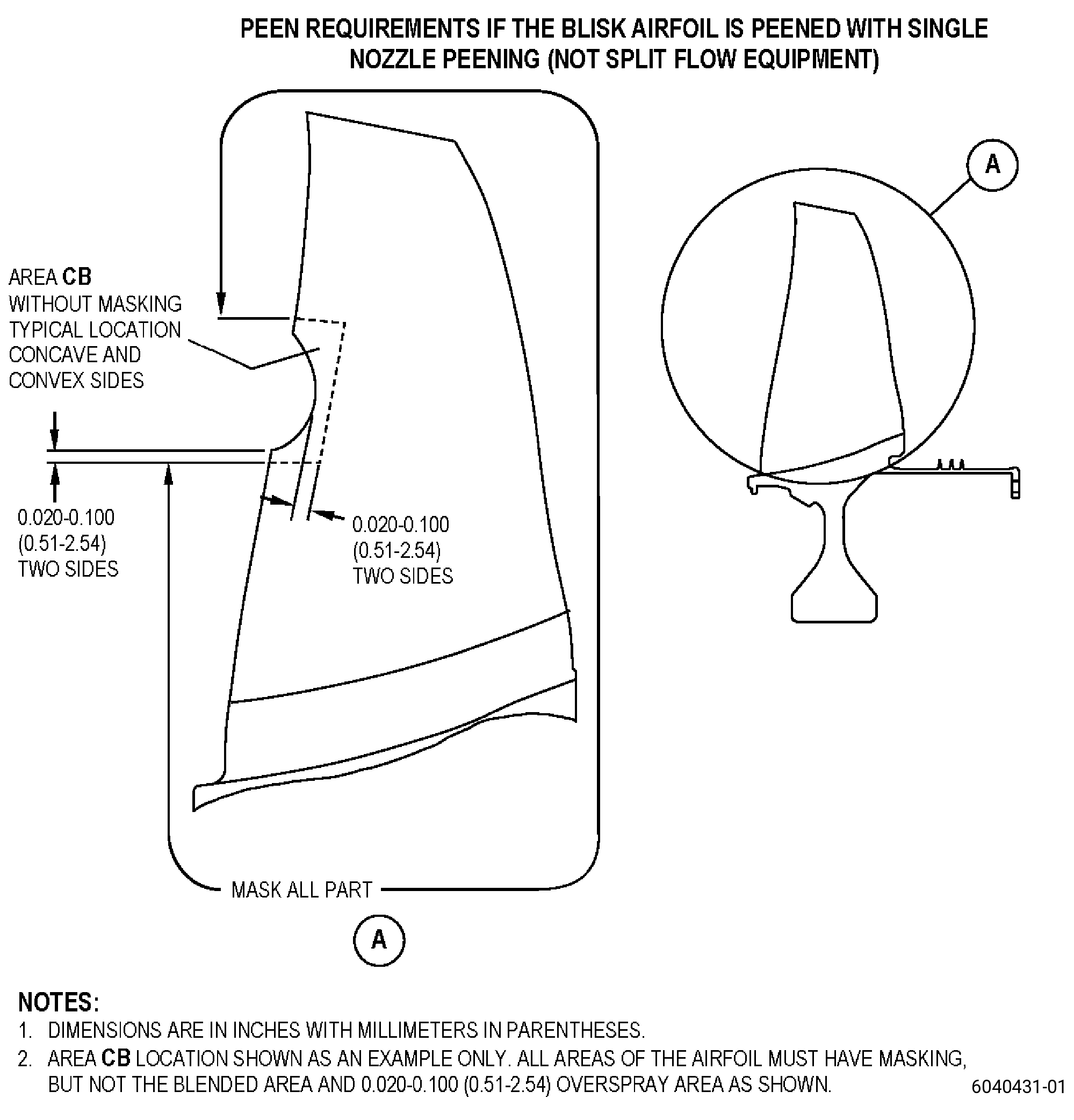
| E.A. | Alternative Procedure. Peen the blisk area CB. Refer to TASK 70-47-01-380-016 (SHOTPEENING), Figure 903, and as follows: |
| (1) | It is permitted to peen one side of the airfoil at a time. |
| (2) | Apply C10-012 masking tape to the areas that you will not peen. |
| (3) | It is necessary to apply masking to all the airfoils that you will not peen. |
| (4) | For the blended airfoils, area CB will not have masking, all other airfoil areas must be have masking. |
| (5) | Use C04-286 S110 cast steel shot. |
| (6) | Peen area to an intensity of 0.006-0.012N. |
| (7) | Make sure that you make the intensity verification in the blisk repair area with a scrap part or simulative fixture. |
| (8) | A minimum coverage of 100 percent is necessary and a maximum coverage of 125 percent is permitted. |
| (9) | Remove the masking tape from the blisk. |
| Subtask 72-31-41-220-064 |
| F. | Do an inspection of the blisk airfoil surface finish as follows: |
| (1) | Use a Surtronics 25+ Profilometer or equivalent GE approved tool. Refer to paragraph 2.A.(2). |
| (2) | Use a 0.010 inch (0.25 mm) cutoff length. |
| (3) | The surface finish of the airfoil must be 20 microinches (0.5 micrometer) or better. |
| Subtask 72-31-41-140-002 |
| WARNING: |
|
| (4) | If necessary, polish the with your hands the blisk repaired area with C10-010 abrasive cloth or equivalent to do a surface finish. |
| Subtask 72-31-41-220-065 |
| G. | Do a final visual inspection of the blisk. Refer to TASK 72-31-41-200-801 (72-31-41, INSPECTION 001). |