| GENX-1B CLEANING,INSPECTION,AND REPAIR MANUAL | Dated: 11/03/2020 | |
| CIR 72-31-45 , REPAIR 004 | ||
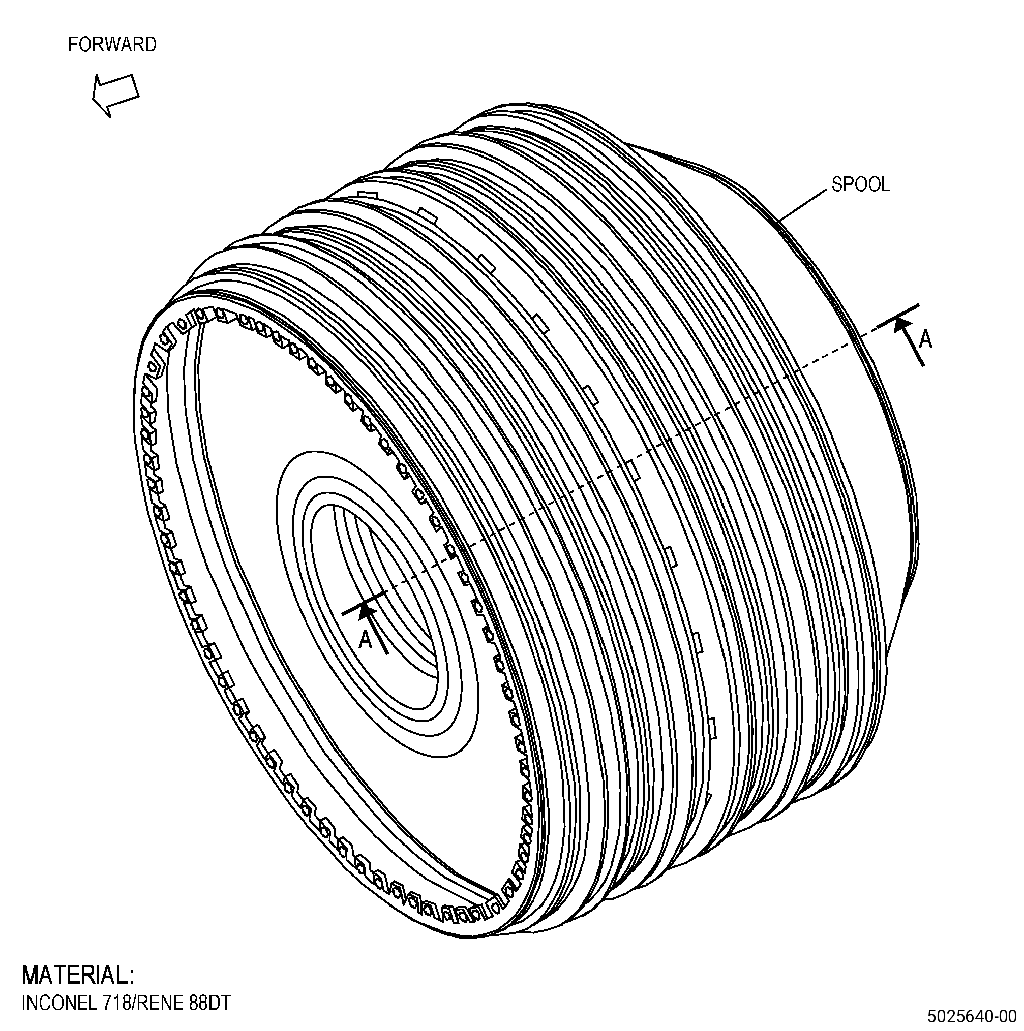
| HIGH PRESSURE COMPRESSOR ROTOR STAGE 6-10 SPOOL - REPAIR - BOLTHOLE REPAIR | ||
| GENX-1B CLEANING,INSPECTION,AND REPAIR MANUAL | Dated: 11/03/2020 | |
| CIR 72-31-45 , REPAIR 004 | ||
| HIGH PRESSURE COMPRESSOR ROTOR STAGE 6-10 SPOOL - REPAIR - BOLTHOLE REPAIR | ||
| * * * FOR ALL |
| TASK 72-31-45-300-805 |
| 1 . | Bolthole Repair. |
| A. | This procedure gives instructions to repair the high pressure compressor rotor stage 6-10 spool (spool) by reaming the flange boltholes. Refer to Figure 901. |
| B. | The following maximum repairable limits apply to this repair: |
| NOTE: |
|
| (4) | Visual Inspection. |
| (i) | Do an inspection of the flange boltholes for: |
| 1 | Nicks, dents, and scratches on the ID of bolthole diameters LT and LU: |
| Maximum repairable limit: |
|
| 2 | Pits: |
| Maximum repairable limit: |
|
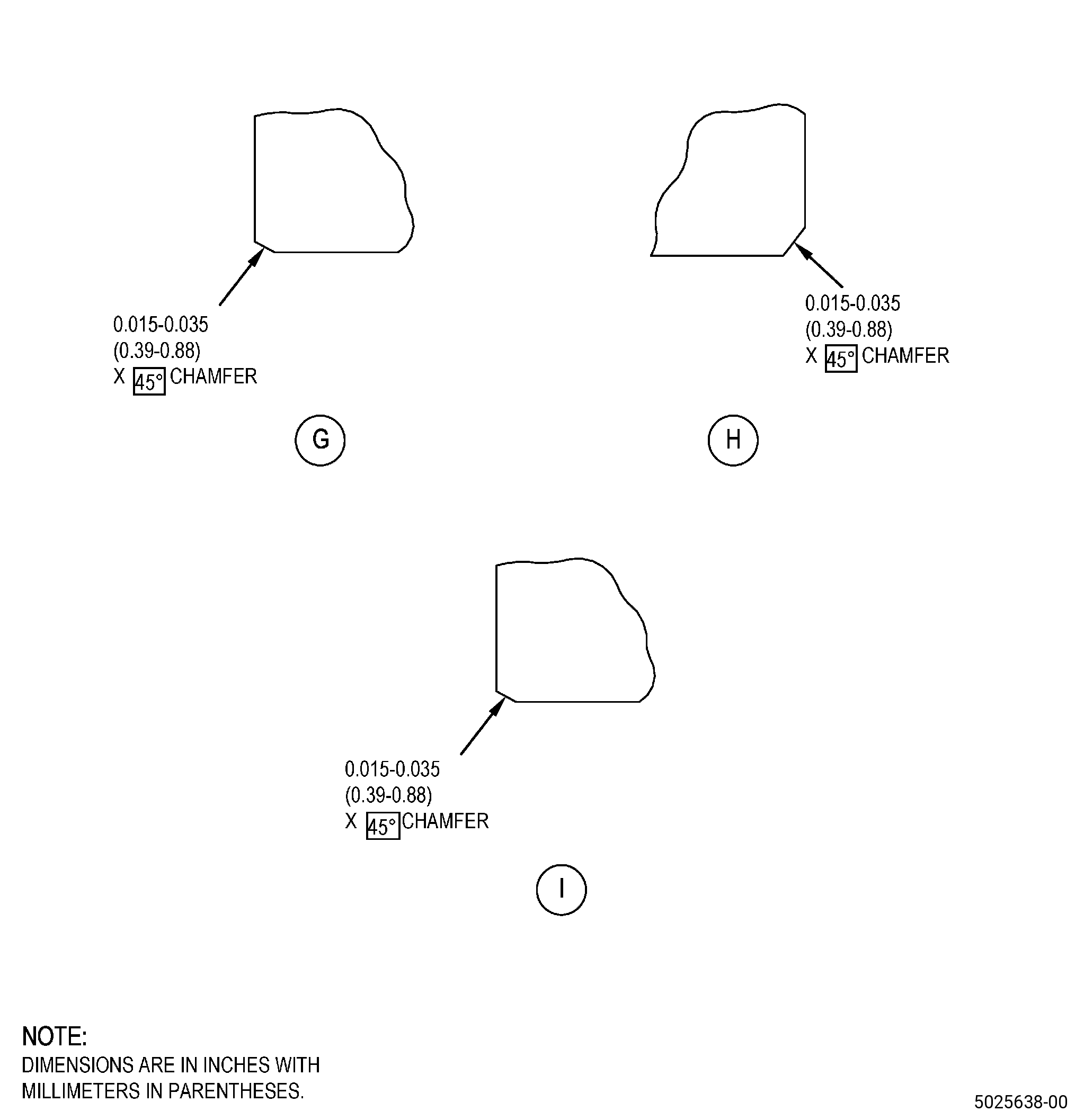
| 3 | Nicks, dents, and scratches on the 45 degree chamfer: |
| Maximum repairable limit: |
|
| 4 | Pits on the 45 degree chamfer: |
| Maximum repairable limit: |
|
| 5 | Fretting, galling, or wear on boltholes: |
| Maximum repairable limit: |
|
| (8) | Bolthole Inspection Procedure. |
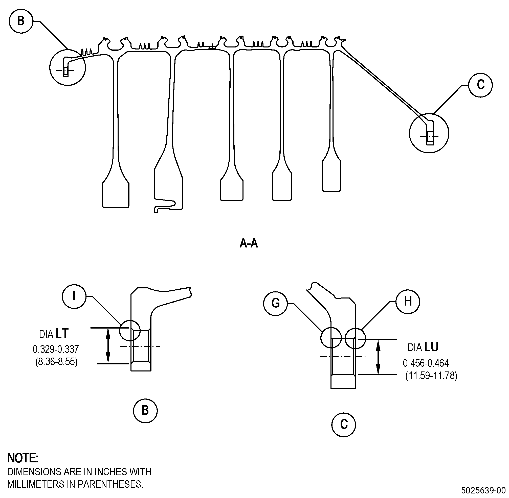
| (b) | Measure the boltholes as follows: |
| 1 | Diameter LT: |
| Minimum repairable limit: |
|
| Maximum repairable limit: |
|
| 2 | Diameter LU: |
| Minimum repairable limit: |
|
| Maximum repairable limit: |
|
| C. | The subsequent table gives a list of the part numbers that are applicable to this repair. All part numbers are applicable to all paragraphs unless specified differently. |
|
||||||||||||||||||||||||||||||||||||
| D. | Proprietary/Complex Process Statement. |
| (1) | None. |
| 2 . | Tools, Equipment, and Materials. |
| NOTE: |
|
| A. | Tools and Equipment. |
| (1) | Special Tools. None. |
| (2) | Standard Tools and Equipment. None. |
| (3) | Locally Manufactured Tools. None. |
| B. | Consumable Materials. |
|
| C. | Referenced Procedures. |
| D. | Expendable Parts. None. |
| E. | SPD Information. |
| (1) | Locally Manufactured SPD. None. |
| F. | Special Solutions. None. |
| G. | Test Specimens. None. |
| 3 . | Dimensional Information. |
| Subtask 72-31-45-220-132 |
| A. | Refer to Figure 901 for specified dimensions and locations. |
| NOTE: |
|
| NOTE: |
|
| 4 . | Setup Information. |
| Subtask 72-31-45-350-012 |
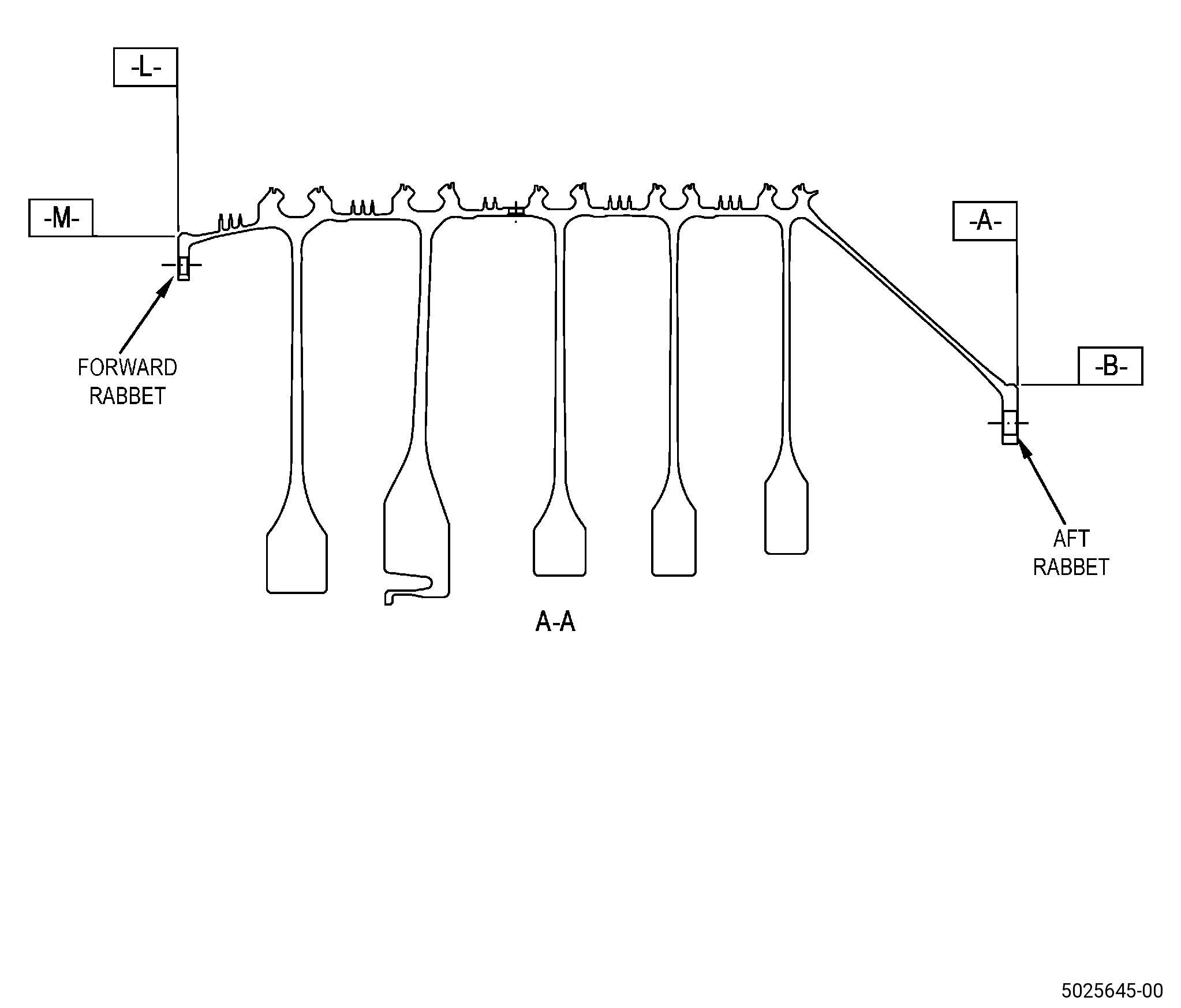
| A. | Set-up the spool for machining/shotpeening. Refer to Figure 903 and as follows: |
| (1) | Set-up the spool for machining/shotpeening the aft rabbet and as follows: |
| (a) | Install the spool in the holding fixture. |
| (b) | Surface A must be flat to 0.001 inch (0.02 mm) or less. |
| (c) | Diameter B must have a runout of 0.001 inch (0.02 mm) or less. |
| (2) | Set-up the spool for machining/shotpeening the forward rabbet and as follows: |
| (a) | Install the spool in the holding fixture. |
| (b) | Surface L must be flat to 0.001 inch (0.02 mm) or less. |
| (c) | Diameter M must have a runout of 0.001 inch (0.02 mm) or less. |
| 5 . | Procedure. |
| Subtask 72-31-45-110-009 |
| A. | If necessary, clean the spool. Refer to TASK 72-31-45-100-801 (72-31-45, CLEANING 001). |
| Subtask 72-31-45-320-005 |
| CAUTION: |
|
| B. | Machine the spool damaged bolthole LT or bolthole LU. Refer to TASK 70-42-02-320-001 (REPAIR PRACTICES FOR HOLE REWORK), Figure 901, and as follows: |
| NOTE: |
|
| (1) | If necessary, set-up the spool for machining the aft rabbet. Refer to Subtask 72-31-45-350-012 (paragraph 4.A.(1)). |
| (2) | If necessary, set-up the spool for machining the forward rabbet. Refer to Subtask 72-31-45-350-012 (paragraph 4.A.(2)). |
| (3) | Ream the spool diameter LT or diameter LU to remove all damage. Make sure that the diameters agree with the finish dimensions. |
| Subtask 72-31-45-350-013 |
| (4) | Blend the chamfer on diameter LT and diameter LU to remove the damage from the spool. Refer to TASK 70-42-00-350-002 (BLENDING AND REMOVAL OF HIGH METAL PROCEDURES) and as follows: |
| (a) | Blend the edges to 0.015-0.035 inch (0.39-0.88 mm) chamfer on the aft face of the forward flange. |
| (b) | Blend the edges to 0.015-0.035 inch (0.39-0.88 mm) chamfer on the aft face of the aft flange. |
| WARNING: |
|
| (5) | Polish the spool boltholes repair areas. Refer to TASK 70-42-01-350-003 (POLISHING BOLTHOLE SURFACES) and as follows: |
| (a) | If necessary, polish the chamfer on the aft flange bolthole to remove the damage as follows: |
| 1 | Polish to a maximum of 0.002 inch (0.05 mm) in depth to fully remove the damage. |
| 2 | Make sure that the polishing area is not more than 50 percent of the bolthole. |
| 3 | Surface finish must be 32 microinches (0.8 micrometer). |
| (b) | Polish the repaired spool boltholes and edges on diameter LU, diameter LT/aft flange bolthole to a surface finish of 32 microinches (0.8 micrometer). |
| Subtask 72-31-45-110-010 |
| C. | Etch the spool repaired areas. Refer to TASK 70-24-00-110-033 (ETCHING PROCEDURES FOR FLUORESCENT-PENETRANT INSPECTION) , TASK 70-24-01-110-034 (SWAB ETCHING PROCEDURE) , and as follows: |
| (1) | Use Class C etchant or Class G etchant. |
| Subtask 72-31-45-230-003 |
| D. | Do an inspection of the spool repair areas. Refer to TASK 70-32-00-200-002 (INDIRECT INSPECTION METHODS), TASK 70-32-03-230-002 (SPOT-FLUORESCENT-PENETRANT INSPECTION), and as follows: |
| (1) | Use Class G penetrant. |
| (2) | Indications are not permitted. |
| Subtask 72-31-45-380-003 |
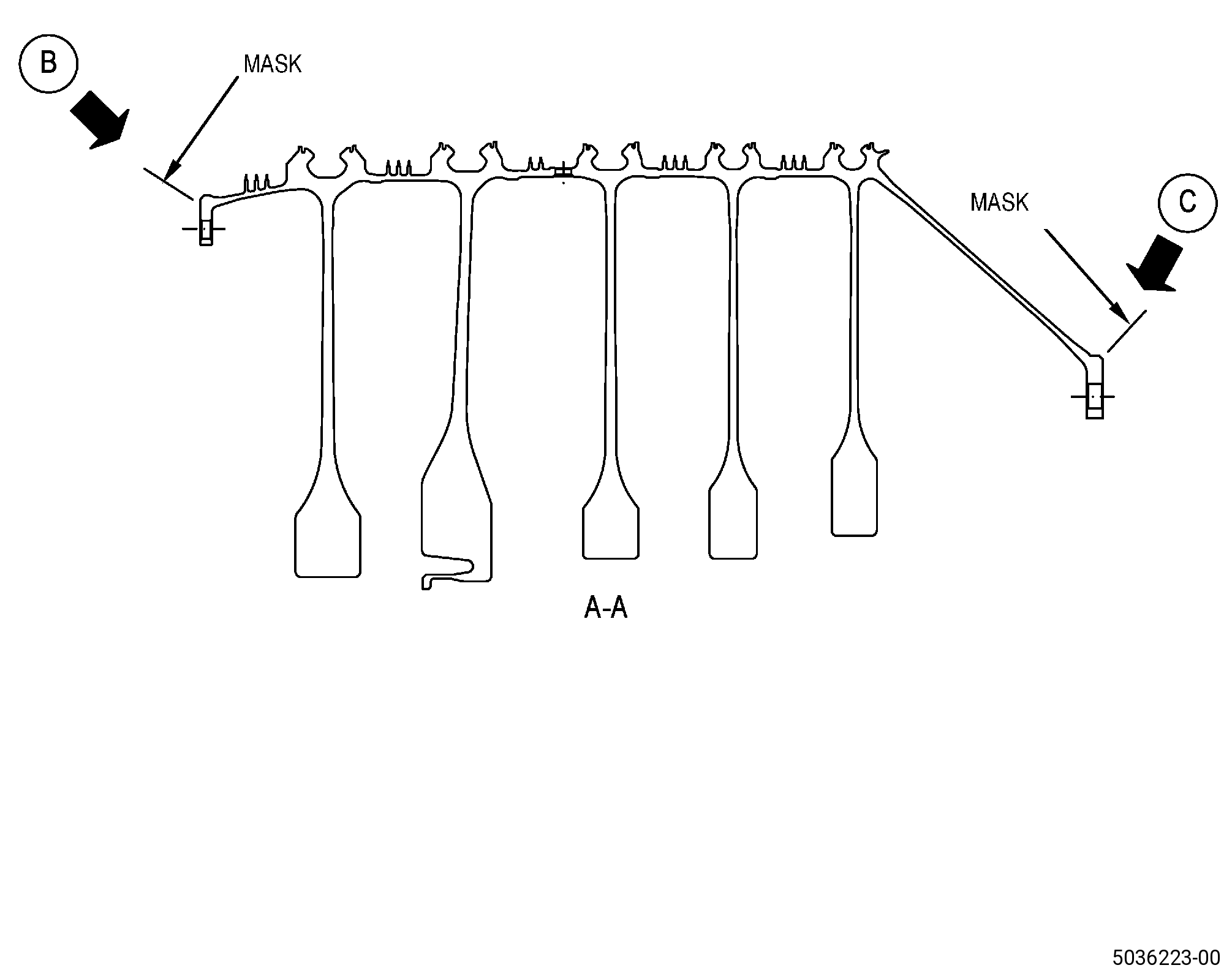
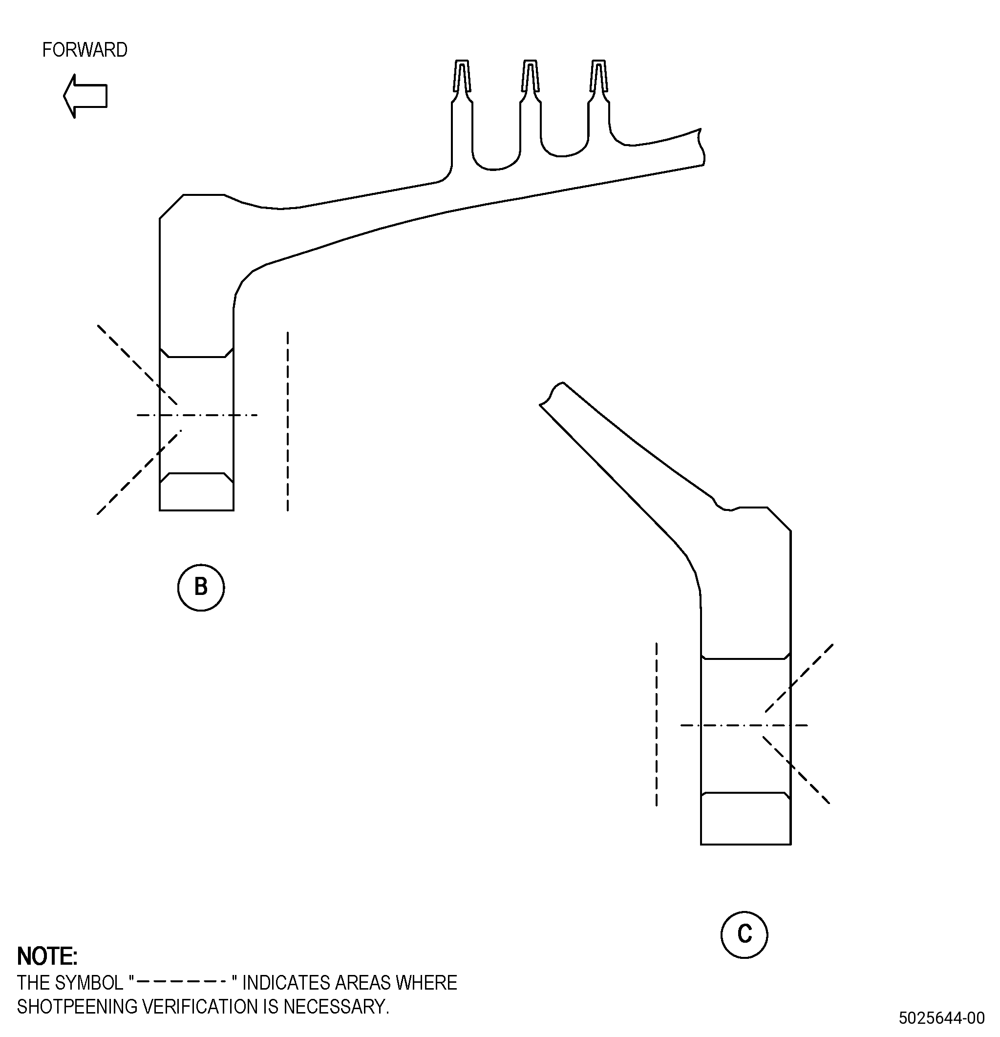
| E. | Peen the spool diameter LT, diameter LU/repaired chamfer on the forward and aft flange bolthole. Refer to TASK 70-47-01-380-016 (SHOTPEENING), Figure 904, and as follows: |
| (1) | If necessary, set-up the spool for shotpeening the aft rabbet. Refer to Subtask 72-31-45-350-012 (paragraph 4.A.(1)). |
| (2) | If necessary, set-up the spool for shotpeening the forward rabbet. Refer to Subtask 72-31-45-350-012 (paragraph 4.A.(2)). |
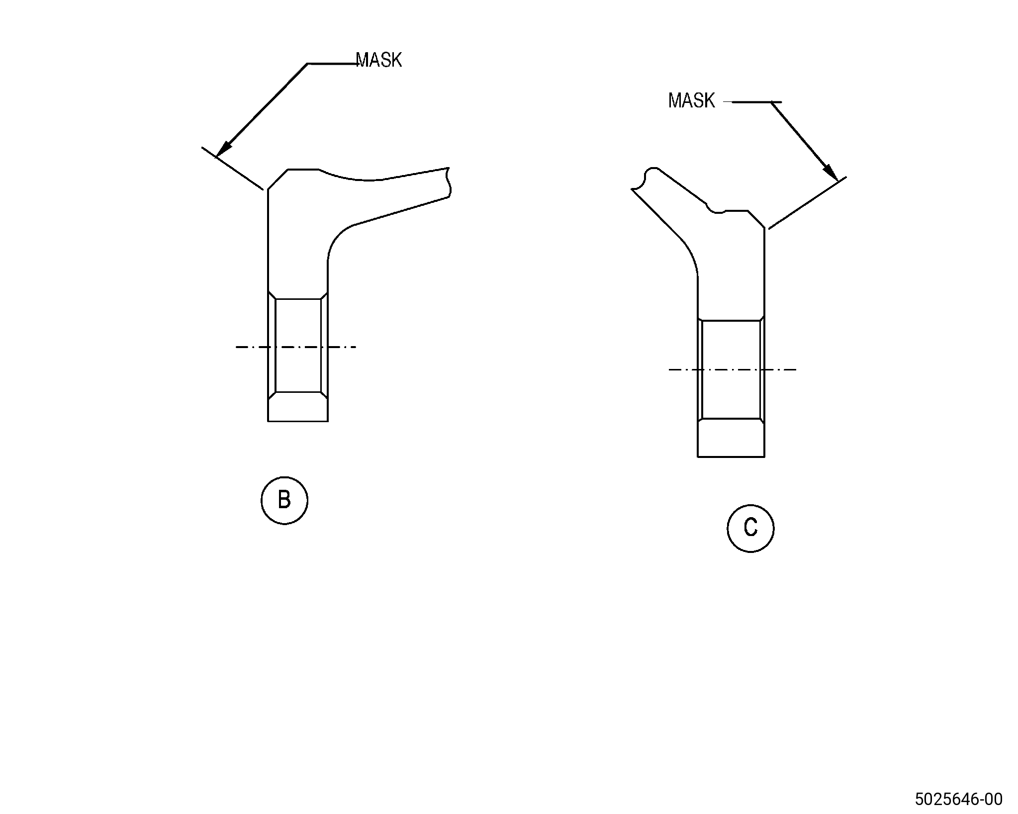
| (3) | Apply C10-021 plastic tape to adjacent areas that you will not peen. Refer to Figure 902. |
| (4) | Use C10-205 Almen N. |
| (5) | Use C04-166 CCW14 shot with an intensity of 0.006-0.012N. |
| (6) | Make sure that you do the intensity verification in a simulative fixture. |
| (7) | Ricochet peening is not permitted. |
| (8) | Remove the plastic tape from the spool. |
| Subtask 72-31-45-110-011 |
| F. | Clean the spool. Refer to TASK 70-21-00-110-051 (CHEMICAL CLEANING) and TASK 70-21-03-160-001 (CLEANING METHOD NO. 3 - STEAM CLEANING). |
| Subtask 72-31-45-220-133 |
| G. | Do a final dimensional inspection of the spool repaired areas. Refer to TASK 72-31-45-200-807 (72-31-45, INSPECTION 001). |