| GENX-1B CLEANING,INSPECTION,AND REPAIR MANUAL | Dated: 10/11/2023 | |
| CIR 72-31-45 , INSPECTION 001 | ||
| HPC ROTOR STAGE 6-10 SPOOL - INSPECTION | ||
| GENX-1B CLEANING,INSPECTION,AND REPAIR MANUAL | Dated: 10/11/2023 | |
| CIR 72-31-45 , INSPECTION 001 | ||
| HPC ROTOR STAGE 6-10 SPOOL - INSPECTION | ||
| * * * FOR ALL |
| TASK 72-31-45-200-807 |
| 1 . | General. |
| A. | This procedure gives instructions to do an inspection of the stages 6-10 compressor rotor spool (spool): |
| • |
|
| • |
|
| • |
|
| B. | Give particular attention to the important areas that follow: |
| • |
|
| • |
|
| • |
|
| • |
|
| • |
|
| • |
|
| • |
|
| • |
|
| • |
|
| 2 . | Tools, Equipment, and Materials. |
| NOTE: |
|
| A. | Tools and Equipment. |
| NOTE: |
|
| (1) | Special Tools. None. |
| (2) | Standard Tools and Equipment. |
| (3) | Locally Manufactured Tools. None. |
| B. | Consumable Materials. |
|
| C. | Referenced Procedures. |
|
| D. | Expendable Parts. None. |
| 3 . | Specific Inspection Procedure. |
| NOTE: |
|
| Subtask 72-31-45-160-001 |
| A. | Make sure you remove the seal teeth coating before you do the inspections. Refer to TASK 72-31-45-100-801 (72-31-45, CLEANING 001). |
| Subtask 72-31-45-230-002 |
| B. | Do a Class G fluorescent penetrant inspection of the spool. Refer to TASK 70-32-02-230-001 (FLUORESCENT PENETRANT INSPECTION). |
| (1) | Give particular attention to the important areas that follow: |
| • |
|
| • |
|
| • |
|
| • |
|
| • |
|
| • |
|
| • |
|
| • |
|
| • |
|
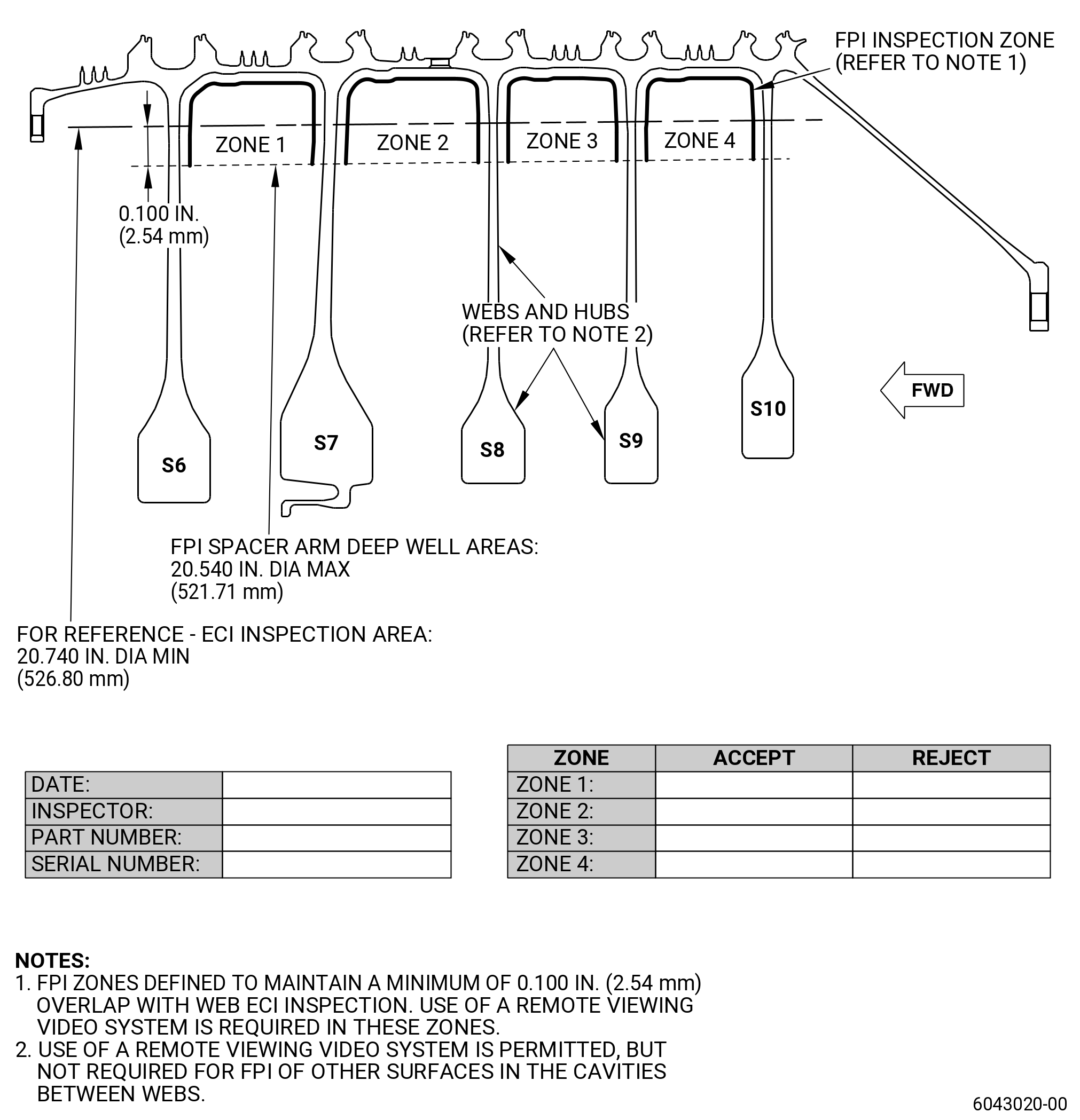
| (2) | Do an inspection of the stage 6-10 spool deep cavity inner surfaces of the spacer arms zone 1 to zone 4 with a remote viewing video system. Refer to TASK 70-32-02-230-001 (FLUORESCENT PENETRANT INSPECTION) (paragraph 1.A.(5)(i)) and Figure 803. |
| (3) | Masking is not necessary. |
| (4) | Indications are not permitted. This does not include indications of 0.015 inch (0.38 mm) or less, which are non-interpretable and permitted. |
| (a) | Optionally indications on the forward or aft pressure faces which are more than 0.015 inch (0.38 mm) can be interpreted at 30X or higher magnification after doing the following steps: |
| 1 | Clean the area with a solvent dampened cotton swab or absorbent material. |
| 2 | Application of dry developer and/or non-aqueous wet developer (NAWD) are not necessary when doing inspections at magnifications of 30X or higher. |
| 3 | Do an inspection in the necessary inspection window for bleed back method (for example 10 minutes). |
| 4 | Do an inspection at 30X or higher magnification at the same circumferential location on the pressure faces as seen with standard magnification (3X, 5X or 10X). |
| Subtask 72-31-45-110-005 |
| C. | Do an eddy current inspection at all inertia weld areas. |
| (1) | Clean the spool. Refer to TASK 72-31-45-100-801 (72-31-45, CLEANING 001). |
| Subtask 72-31-45-250-001 |
| (2) | Do an eddy current inspection of the inertia weld surfaces both inside diameter (ID) and outside diameter (OD). Refer to TASK 70-32-86-250-801 (ENHANCED 2 MHZ EDDY CURRENT INSPECTION OF LIFE LIMITED HARDWARE USING SYSTEMS UNDER COMPUTER, NUMERIC, OR ROBOTIC CONTROL). |
| NOTE: |
|
| NOTE: |
|
| NOTE: |
|
| NOTE: |
|
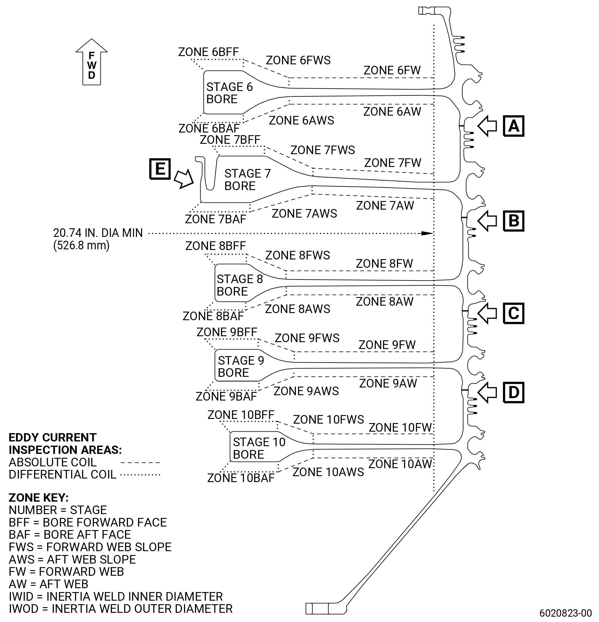
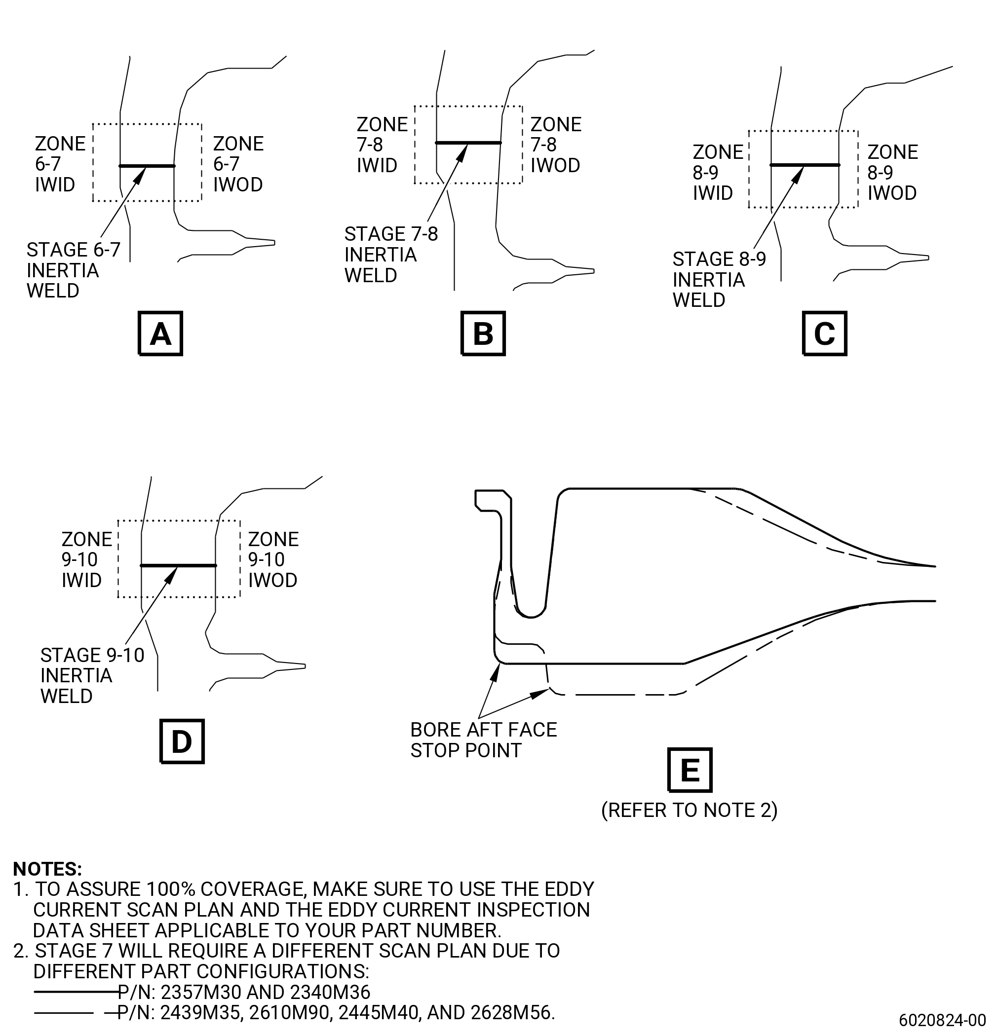
| (a) | Inspect the inertia weld areas (zone 6-7, zone 7-8, zone 8-9, and zone 9-10) shown in the eddy current scan plan. Refer to Figure 801. |
| 1 | Use probe US-3815 for both ID and OD inspection. |
| 2 | Deleted. |
| (b) | Record the calibration data and inspection results on the eddy current inspection data sheet. Refer to Figure 802. |
| (c) | Eddy current inspection evaluation limits. |
| 1 | The evaluation limit for the inertia welds is 1000 mV. |
| (d) | Eddy current inspection reject limits. |
| 1 | The reject limit for the inertia welds is 1000 mV or greater, after evaluation is complete. |
| (e) | All stage 6-10 spool that are rejected by the limits in Subtask 72-31-45-250-001 (paragraph 3.C.(2)(d)) are not serviceable. |
| (f) | All stage 6-10 spool that are not rejected by the limits in Subtask 72-31-45-250-001 (paragraph 3.C.(2)(d)) are serviceable. |
| (g) | Make sure that all records that were made during the eddy current inspection are as complete as possible. Permanently keep these records for each spool that was inspected. |
| Subtask 72-31-45-160-002 |
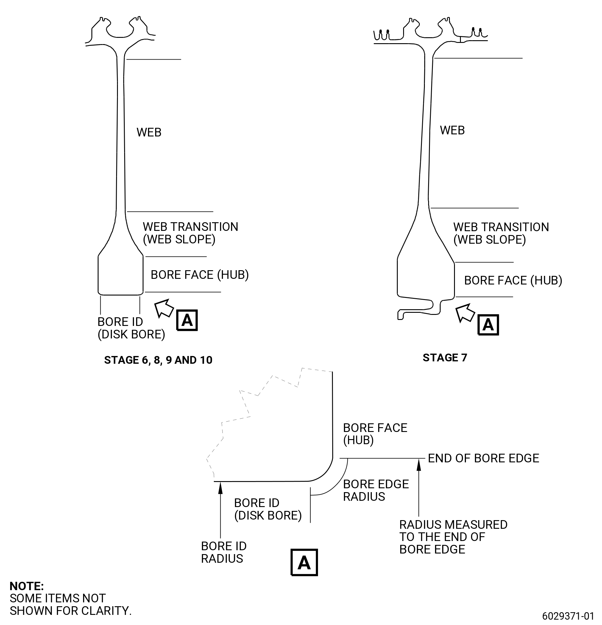
| D. | Do an eddy current inspection of all spool webs, web slopes and bore faces. |
| (1) | Clean the spool. Refer to TASK 72-31-45-100-801 (72-31-45, CLEANING 001). |
| Subtask 72-31-45-250-002 |
| (2) | Do an eddy current inspection of the spool webs, web slopes and bore faces both forward and aft surface. Refer to TASK 70-32-86-250-801 (ENHANCED 2 MHZ EDDY CURRENT INSPECTION OF LIFE LIMITED HARDWARE USING SYSTEMS UNDER COMPUTER, NUMERIC, OR ROBOTIC CONTROL). |
| NOTE: |
|
| NOTE: |
|
| NOTE: |
|
| NOTE: |
|
| (a) | Do an inspection of all the zones on the webs, web slopes, and bores shown in the eddy current scan plan. Refer to Figure 801 for zone definitions. |
| 1 | Use probe US-3813 for web and web slopes inspection. |
| 2 | Use probe US-3800 for bore faces inspection. |
| (b) | Record the calibration data and inspection results on the eddy current inspection data sheet. Refer to Figure 802. |
| (c) | Eddy current inspection evaluation limits. |
| 1 | The evaluation limit for the webs, web slopes, and bore faces is 500 mV. |
| Subtask 72-31-45-250-003 |
| (d) | Eddy current inspection reject limits. |
| 1 | The reject limit for the spool webs, web slopes and bore faces is 500 mV or greater, after the evaluation is complete. |
| (e) | All the stages 6-10 spool that are not rejected by the limits in Subtask 72-31-45-250-003 (paragraph 3.D.(2)(d)) are serviceable. |
| (f) | All the web slopes and bore faces (zones 6-10BFF, 6-10FWS, 6-10BAF, and 6-10AWS) of stages 6-10 spool that are rejected by the limits in Subtask 72-31-45-250-003 (paragraph 3.D.(2)(d)) are not serviceable. Refer to Figure 801 for zone definitions. |
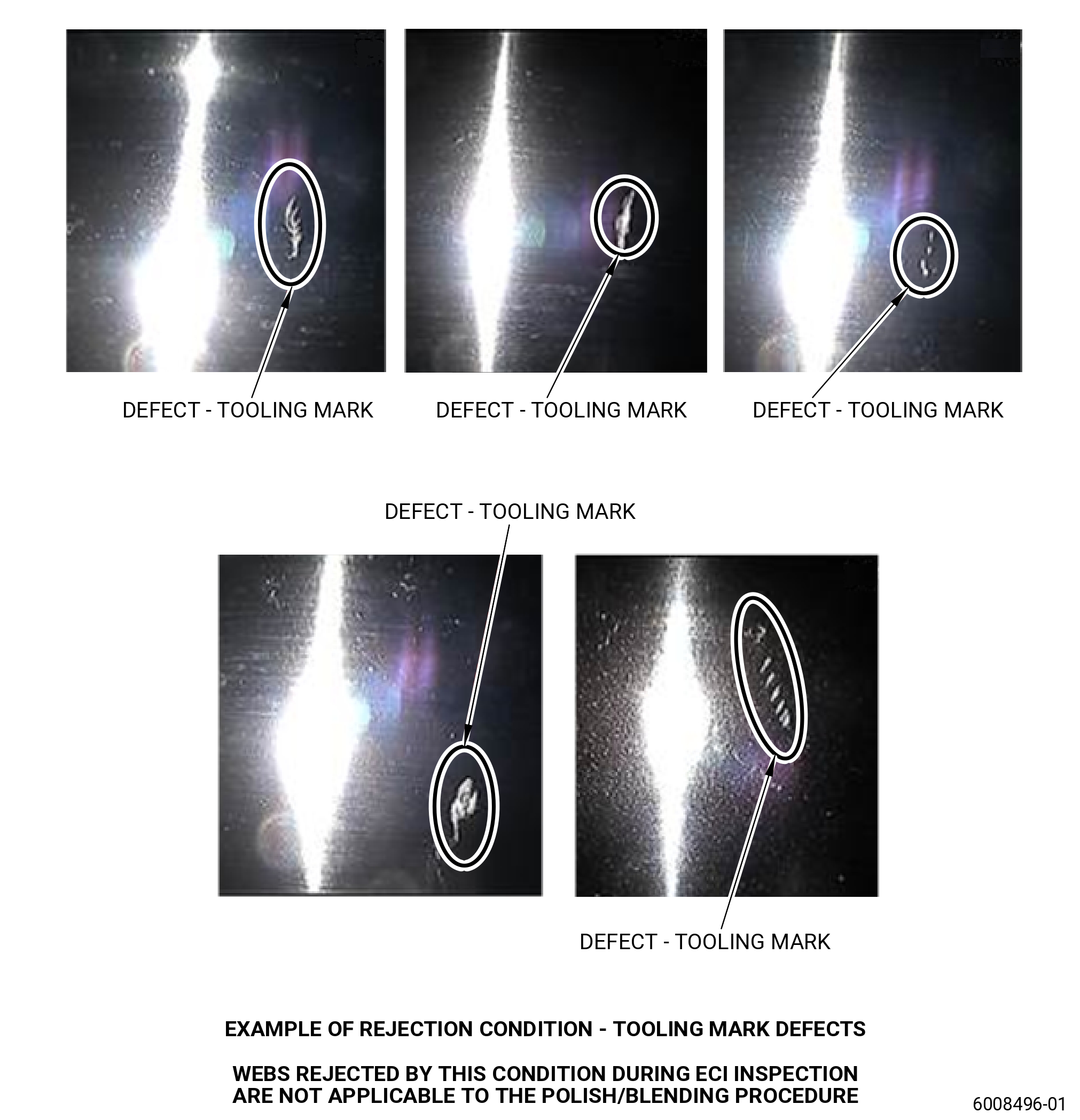
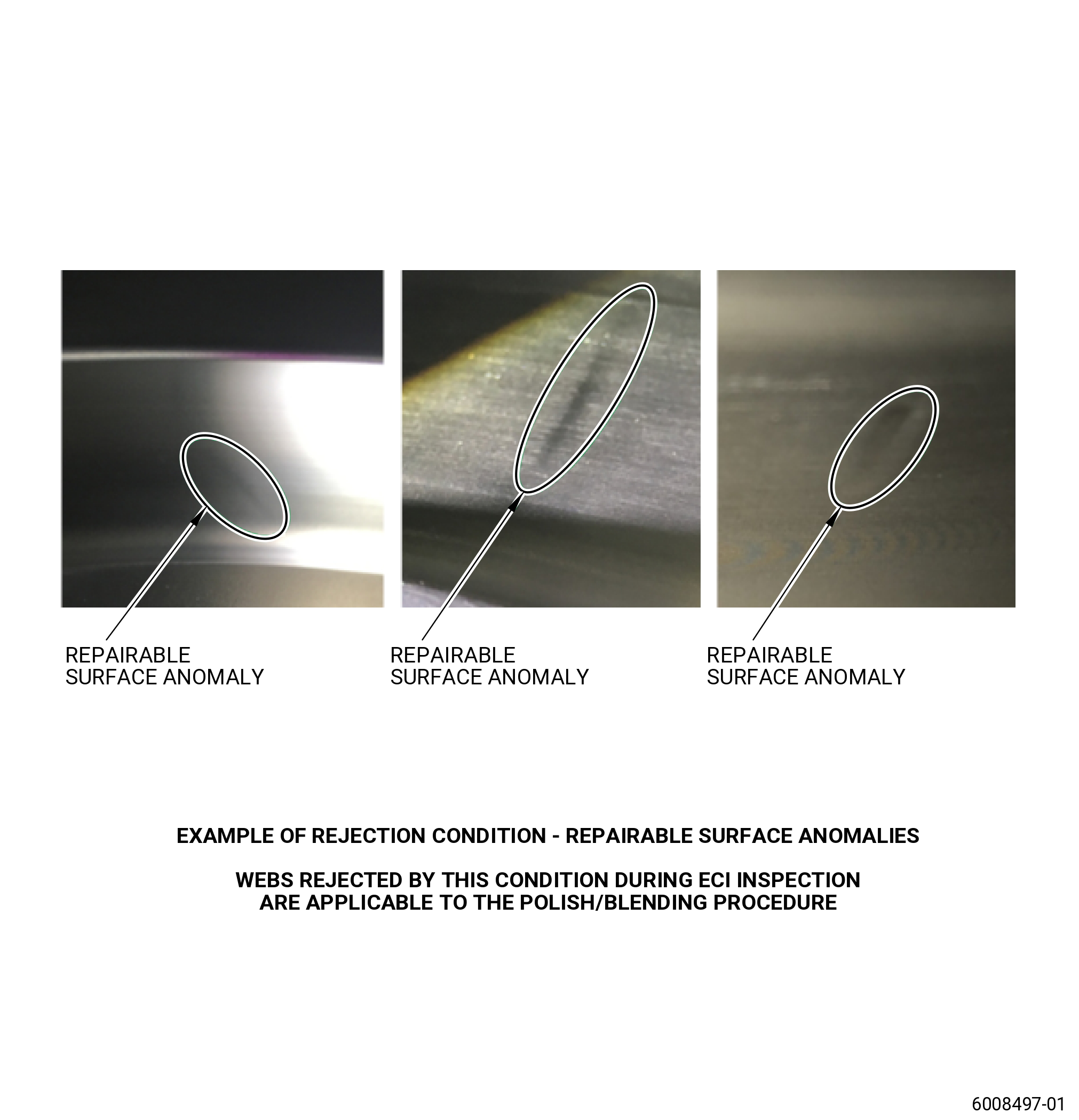
| (g) | All the webs (zones 6-10FW and 6-10AW) of stages 6-10 spool that are rejected by the limits in Subtask 72-31-45-250-003 (paragraph 3.D.(2)(d)) , determine if the indication is a defect, or if it can be an repairable surface anomaly. Refer to Figure 801 and Figure 804 and evaluate as follows: |
| 1 | If it is a defect on the spool web, the part is not serviceable. This condition cannot be repaired. Refer to Figure 804 and as follows: |
| a | It is not permitted to use polish/blend procedure for tooling marks, nicks, dents or any other type of indications that are not acceptable. |
| 2 | If the indication on the spool web is an repairable surface anomaly (surface waviness or blended surface), polish/blend the indication. Refer to TASK 70-42-00-350-002 (BLENDING AND REMOVAL OF HIGH METAL PROCEDURES), Subtask 70-42-00-350-038 (paragraph C.(3)(e)) and as follows: |
| a | Make and record at least one photograph of the rejected area if not already done. |
| CAUTION: |
|
| b | Polish/blend to remove the defect, it is permitted to polish/blend 360 degrees if necessary. |
| c | Maximum depth of 0.002 inch (0.05 mm) and minimum radius of 0.5 inch (12.7 mm) are required. |
| NOTE: |
|
| 3 | Do an eddy current inspection of the polish/blended area again. Refer to Subtask 72-31-45-160-002 (paragraph 3.D.) and as follows: |
| a | If any rejection is found, do paragraph 3.D.(2)(f) again and as follows: |
| (1) | Total cumulative polish/blend must be in the limits of paragraph 3.D.(2)(f)2(c). |
| 4 | Peen the repaired area of the spool web. Refer to TASK 70-47-01-380-016 (SHOTPEENING) and as follows: |
| a | Apply C10-021 plastic tape to the areas you will not peen. |
| b | Coverage must be a minimum of 125 percent. |
| c | An intensity verification is necessary with a simulative fixture. |
| d | Use C04-166 CCW14 cut wire shot. |
| e | Intensity must be 0.006-0.012N. |
| f | Overspray is permitted. |
| g | Remove all plastic tape. |
| (h) | Make sure that all records that were made during the eddy current inspection are as complete as possible. Permanently keep these records for each spool that was inspected. |
| 4 . | Visual Inspection. |
| Refer to Figure 806. |
| Subtask 72-31-45-220-156 |
| A. | Visual inspection serviceable limits for wear, fretting, galling, and REPAIR 006 are not applicable to the stage 8 portion of the HPC rotor stage 6-10 spool P/N 2628M56G01 with part serial numbers listed in GEnx-1B SB 72-0484 Table 1. The stage 8 portion is defined as the area between the inertia welds defined as B and C on Figure 801. |
| Subtask 72-31-45-220-157 |
| B. | Visual inspection serviceable limits for nicks, dents, scratches, wear, fretting, galling, and REPAIR 006 are not applicable to the stage 8 portion of the HPC rotor stage 6-10 spool P/N 2628M56G01 with part serial numbers listed in GEnx-1B SB 72-0484 Table 2. The stage 8 portion is defined as the area between the inertia welds defined as B and C on Figure 801. |
| Subtask 72-31-45-220-045 |
| C. | Do an inspection of all surfaces (does not include the interstage seal teeth) for: |
| (1) | Cracks: |
| Maximum serviceable limit: |
|
| Repair method: |
|
| Subtask 72-31-45-220-046 |
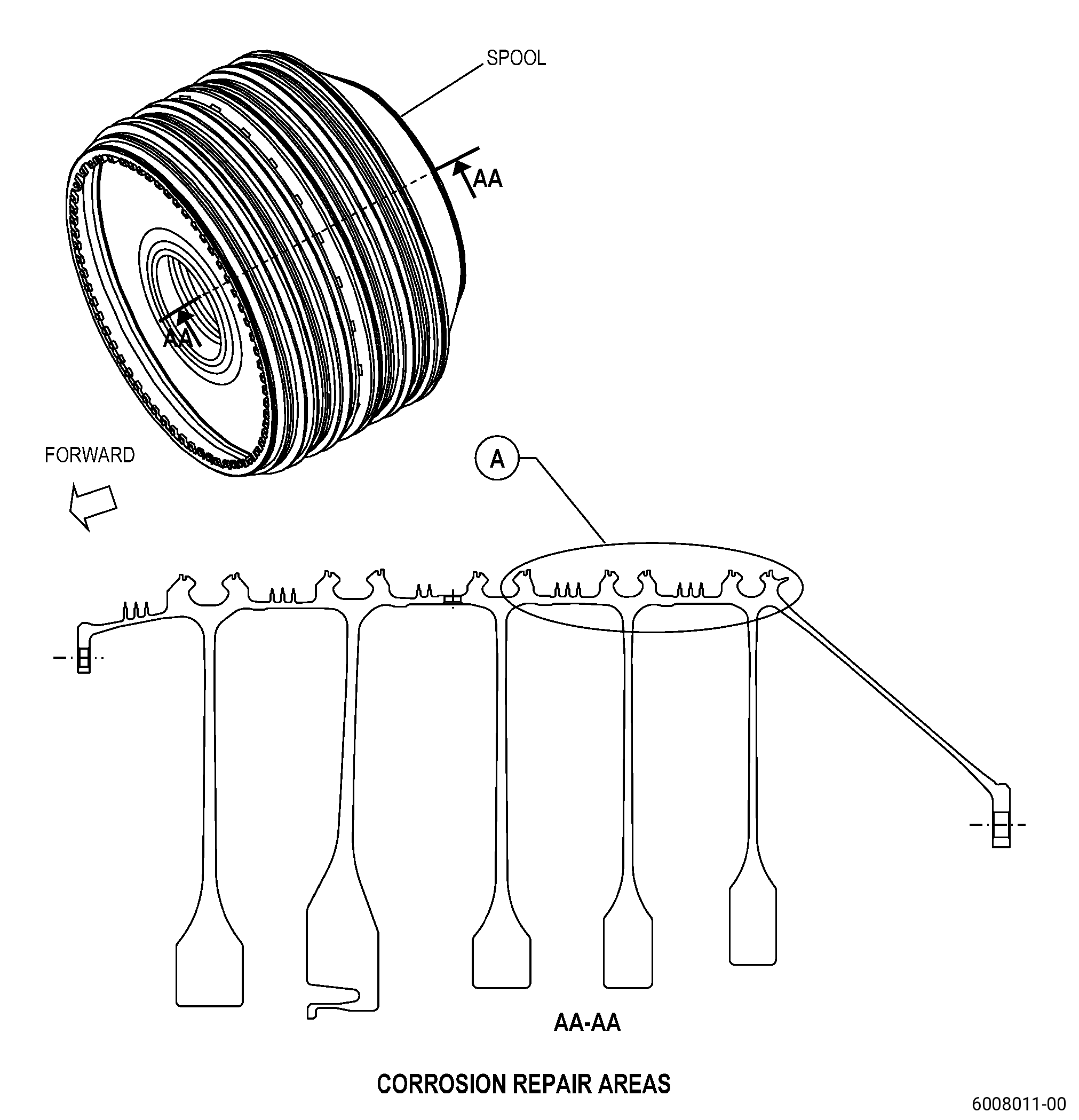
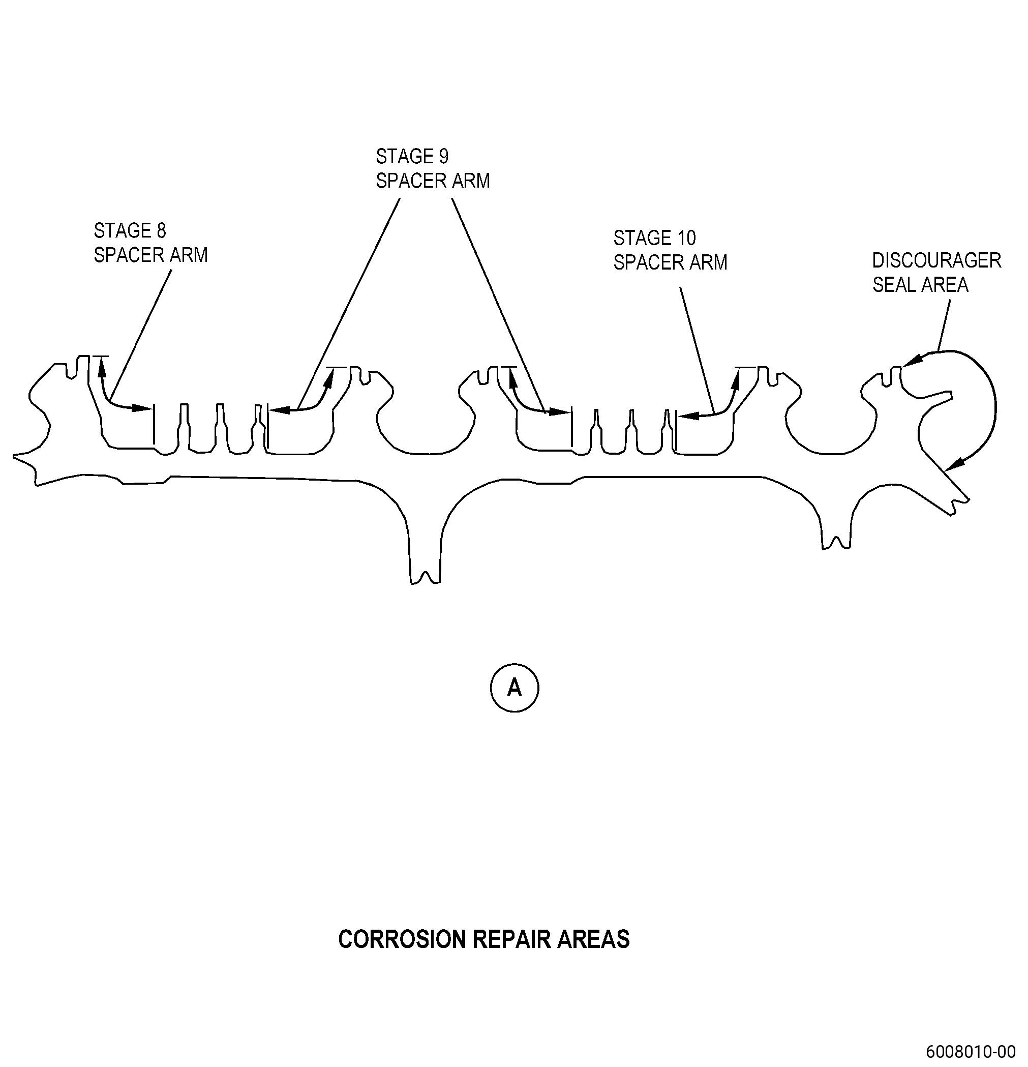
| (2) | Pitting on all areas of the spool (does not include the stage 6 spacer arm, the stage 7 spacer arm, the stage 8 spacer arm, the stage 9 spacer arm, the stage 10 spacer arm, and/or the discourager seal) caused by corrosion (identified by black or green deposits): |
| Maximum serviceable limit: |
|
| Repair method: |
|
| Subtask 72-31-45-220-047 |
| (3) | Red deposits or oxidation without pits: |
| Maximum serviceable limit: |
|
| Repair method: |
|
| Subtask 72-31-45-220-144 |
| (4) | Pitting on the stage 6 spacer arm caused by corrosion (identified by black or green deposits): |
| Maximum serviceable limit: |
|
| Repair method: |
|
| Subtask 72-31-45-220-145 |
| (5) | Pitting on the stage 7 spacer arm caused by corrosion (identified by black or green deposits): |
| Maximum serviceable limit: |
|
| Repair method: |
|
| Subtask 72-31-45-220-146 |
| (6) | Pitting on the stage 8 spacer arm caused by corrosion (identified by black or green deposits): |
| Maximum serviceable limit: |
|
| Repair method (for stage 6-10 spool part number 2628M56G01 with part serial numbers listed in GEnx-1B SB 72-0484): |
|
| Repair method: |
|
| Subtask 72-31-45-220-147 |
| (7) | Pitting on the stage 9 spacer arm caused by corrosion (identified by black or green deposits): |
| Maximum serviceable limit: |
|
| Repair method: |
|
| Subtask 72-31-45-220-148 |
| (8) | Pitting on the stage 10 spacer arm caused by corrosion (identified by black or green deposits): |
| Maximum serviceable limit: |
|
| Repair method: |
|
| Subtask 72-31-45-220-149 |
| (9) | Pitting on the discourager seal caused by corrosion (identified by black or green deposits): |
| Maximum serviceable limit: |
|
| Repair method: |
|
| Subtask 72-31-45-220-048 |
| D. | Do an inspection of the flange mating faces for: |
| (1) | Pickup and high metal: |
| Maximum serviceable limit: |
|
| Repair method: |
|
| Subtask 72-31-45-220-049 |
| (2) | Nicks, dents, pits, and scratches: |
| Maximum serviceable limit: |
|
| Repair method: |
|
| Subtask 72-31-45-220-050 |
| (3) | Fretting, galling, and wear: |
| Maximum serviceable limit: |
|
| Repair method: |
|
| Subtask 72-31-45-220-052 |
| E. | Do an inspection of the forward rabbet for: |
| (1) | Nicks, dents, and scratches on parent metal: |
| Maximum serviceable limit: |
|
| Repair method: |
|
| Subtask 72-31-45-220-053 |
| (2) | Fretting, galling, or wear on parent metal: |
| Maximum serviceable limit: |
|
| Repair method: |
|
| Subtask 72-31-45-220-054 |
| (3) | Corrosion pits on parent metal: |
| Maximum serviceable limit: |
|
| Repair method: |
|
| Subtask 72-31-45-220-103 |
| (4) | Chipped or missing HVOF or APS coating: |
| Maximum serviceable limit: |
|
| Repair method: |
|
| NOTE: |
|
| Subtask 72-31-45-220-104 |
| F. | Do an inspection of the aft rabbet for: |
| (1) | Nicks, dents, and scratches: |
| Maximum serviceable limit: |
|
| Repair method: |
|
| Subtask 72-31-45-220-105 |
| (2) | Fretting, galling, or wear: |
| Maximum serviceable limit: |
|
| Repair method: |
|
| Subtask 72-31-45-220-106 |
| (3) | Corrosion pits: |
| Maximum serviceable limit: |
|
| Repair method: |
|
| NOTE: |
|
| Subtask 72-31-45-220-055 |
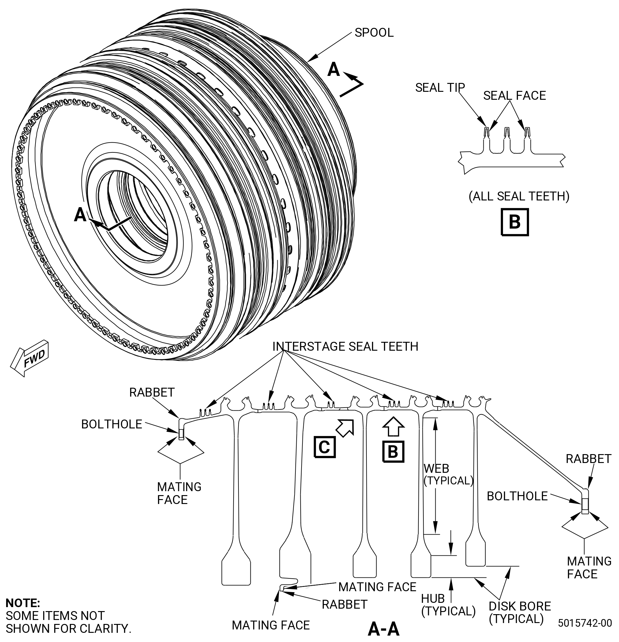
| G. | Do an inspection of the interstage seal teeth for: |
| (1) | Cracks: |
| Maximum serviceable limit: |
|
| Repair method: |
|
| Subtask 72-31-45-220-056 |
| (2) | Chipped or missing coating after you apply the coating again: |
| Maximum serviceable limit: |
|
| Repair method: |
|
| Subtask 72-31-45-220-099 |
| (3) | Nicks, dents, and scratches on seal teeth diameter FU only: |
| Maximum serviceable limit: |
|
| Maximum repairable limit: |
|
| Repair method: |
|
| • |
|
| • |
|
| • |
|
| • |
|
| • |
|
| NOTE: |
|
| NOTE: |
|
| NOTE: |
|
| NOTE: |
|
| NOTE: |
|
| Subtask 72-31-45-220-057 |
| (4) | Nicks, dents, and scratches on seal teeth diameter DH, diameter DE, diameter KG, and diameter KN: |
| Maximum serviceable limit (for stage 6-10 spool part number 2628M56G01 with part serial numbers listed in GEnx-1B SB 72-0484 Table 2): |
|
| Maximum serviceable limit: |
|
| Maximum repairable limit: |
|
| Repair method: |
|
| • |
|
| • |
|
| • |
|
| • |
|
| • |
|
| NOTE: |
|
| NOTE: |
|
| NOTE: |
|
| NOTE: |
|
| NOTE: |
|
| Subtask 72-31-45-220-058 |
| (5) | Seal tip wear into the parent metal: |
| Maximum serviceable limit: |
|
| Repair method: |
|
| Subtask 72-31-45-220-059 |
| (6) | Seal face wear into the parent metal: |
| Maximum serviceable limit: |
|
| Repair method: |
|
| Subtask 72-31-45-220-060 |
| (7) | Pits: |
| Maximum serviceable limit: |
|
| Repair method: |
|
| Subtask 72-31-45-220-110 |
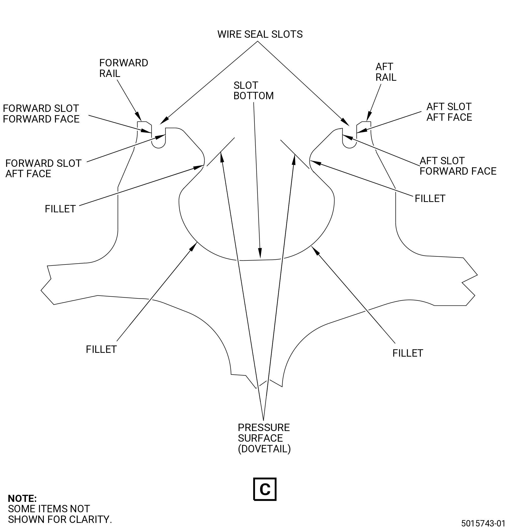
| H. | Do an inspection of the dovetail forward and aft rail for: |
| (1) | Nicks, dents, and scratches on the stage 6, 7, and 8 dovetail rails: |
| Maximum serviceable limit: |
|
| Maximum repairable limit: |
|
| Repair method: |
|
| Subtask 72-31-45-220-111 |
| (2) | Nicks, dents, and scratches on the stage 9 and 10 dovetail rail: |
| Maximum serviceable limit: |
|
| Maximum repairable limit: |
|
| Repair method: |
|
| Subtask 72-31-45-220-061 |
| I. | Do an inspection of the dovetail pressure surfaces and fillets for: |
| (1) | Fretting or galling: |
| Maximum serviceable limit (for stage 6-10 spool part number 2628M56G01 with part serial numbers listed in GEnx-1B SB 72-0484): |
|
| Maximum serviceable limit: |
|
| Repair method: |
|
| Subtask 72-31-45-220-062 |
| (2) | Nicks, dents, and scratches in fillet: |
| Maximum serviceable limit: |
|
| Repair method: |
|
| Subtask 72-31-45-220-063 |
| (3) | Nicks, dents, and scratches on the pressure face: |
| Maximum serviceable limit (for stage 6-10 spool part number 2628M56G01 with part serial numbers listed in GEnx-1B SB 72-0484 Table 2): |
|
| Maximum serviceable limit: |
|
| Repair method: |
|
| Subtask 72-31-45-220-064 |
| (4) | Pits: |
| Maximum serviceable limit: |
|
| Repair method: |
|
| Subtask 72-31-45-220-065 |
| J. | Do an inspection of the dovetail slot bottoms for: |
| (1) | Nicks and dents: |
| Maximum serviceable limit: |
|
| Repair method: |
|
| Subtask 72-31-45-220-066 |
| (2) | Circumferential and axial scratches: |
| Maximum serviceable limit: |
|
| Maximum repairable limit: |
|
| Repair method: |
|
| Subtask 72-31-45-220-067 |
| (3) | Fretting marks from blade lock set screw: |
| Maximum serviceable limit: |
|
| Maximum repairable limit: |
|
| Repair method: |
|
| Subtask 72-31-45-220-068 |
| K. | Do an inspection of the flange boltholes for: |
| (1) | Nicks, dents, and scratches on the ID of bolthole diameters LT and LU: |
| Maximum serviceable limit: |
|
| Maximum repairable limit: |
|
| Repair method: |
|
| Subtask 72-31-45-220-069 |
| (2) | Pits: |
| Maximum serviceable limit: |
|
| Repair method: |
|
| Subtask 72-31-45-220-070 |
| (3) | Nicks, dents, and scratches on the 45 degree chamfer: |
| Maximum serviceable limit: |
|
| Maximum repairable limit: |
|
| Repair method: |
|
| Subtask 72-31-45-220-071 |
| (4) | Pits on the 45 degree chamfer: |
| Maximum serviceable limit: |
|
| Repair method: |
|
| Subtask 72-31-45-220-072 |
| (5) | Fretting, galling, or wear on boltholes: |
| Maximum serviceable limit: |
|
| Maximum repairable limit: |
|
| Repair method: |
|
| L. | Do an inspection of stage 6-10 spool disk for: |
| Subtask 72-31-45-220-150 |
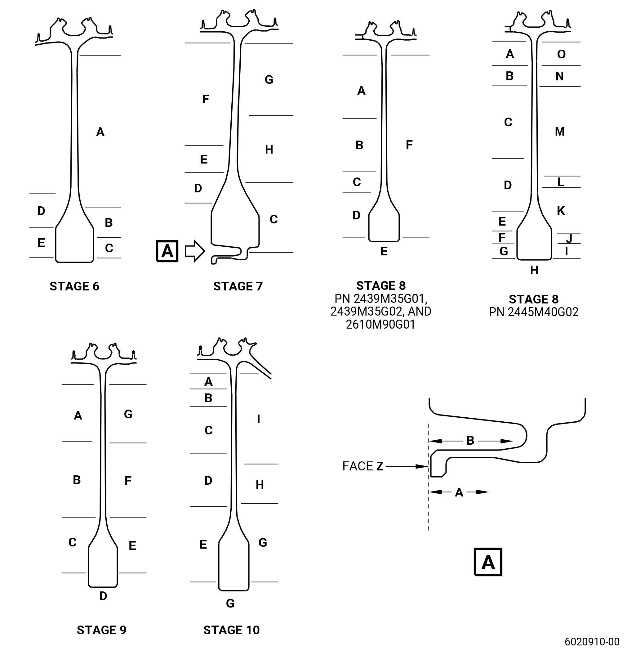
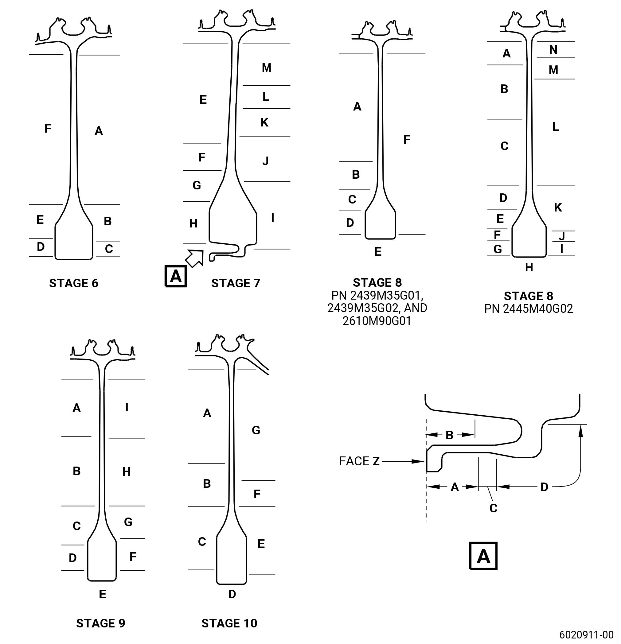
| (1) | For part numbers 2439M35G01, 2439M35G02, 2445M40G02, and 2610M90G01: |
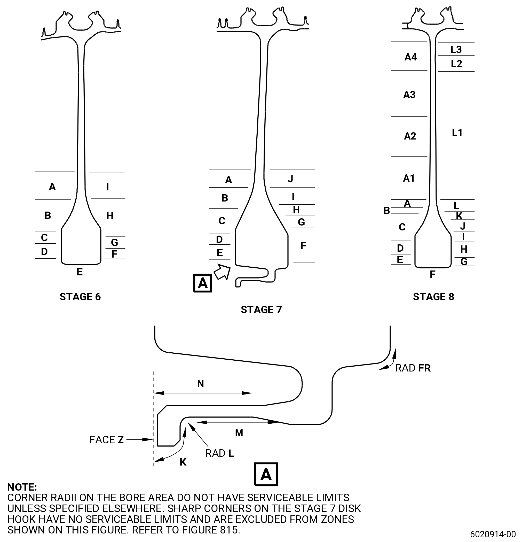
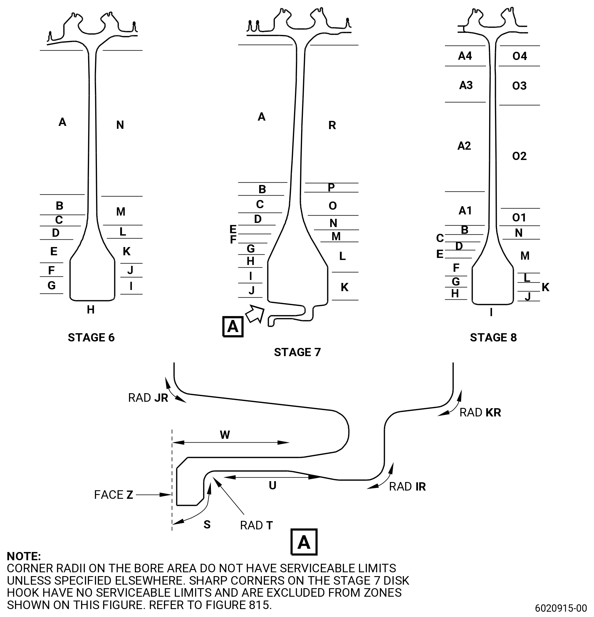
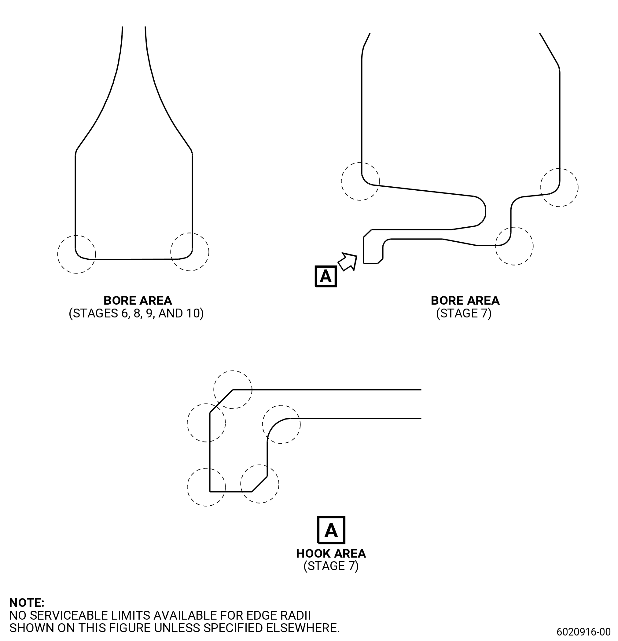
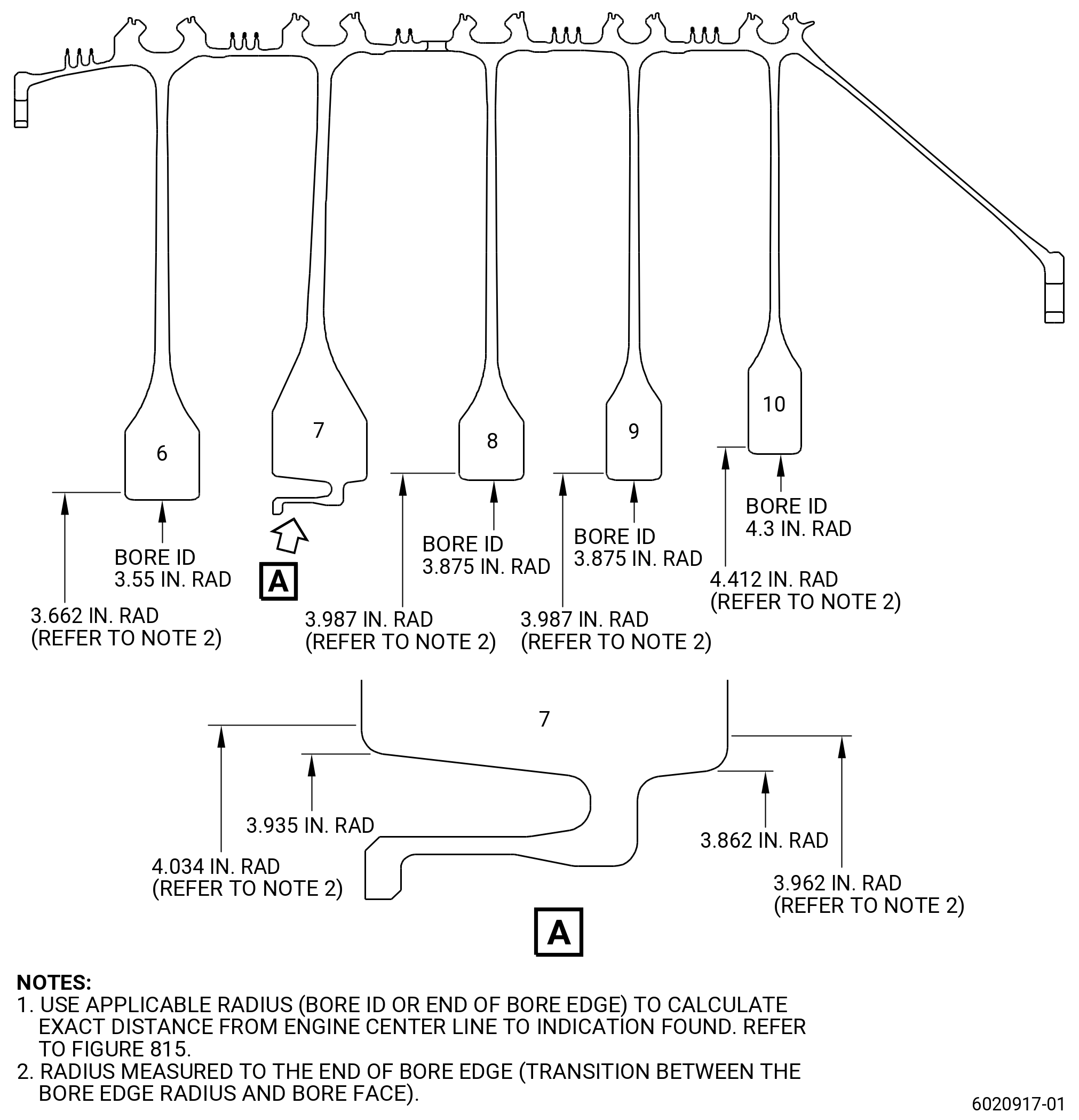
| (a) | Scratches on web, hub, web slope, bore surfaces (does not include bore edge corner radius), and stage 7 disk hook (does not include all corner radii, refer to Figure 815): |
| Maximum serviceable limit: |
|
| Repair method: |
|
| (b) | Nicks and dents on web, hub, web slope, bore surfaces (does not include bore edge corner radius), and stage 7 disk hook (does not include all corner radii, refer to Figure 815): |
| Maximum serviceable limit: |
|
| Repair method: |
|
| Subtask 72-31-45-220-151 |
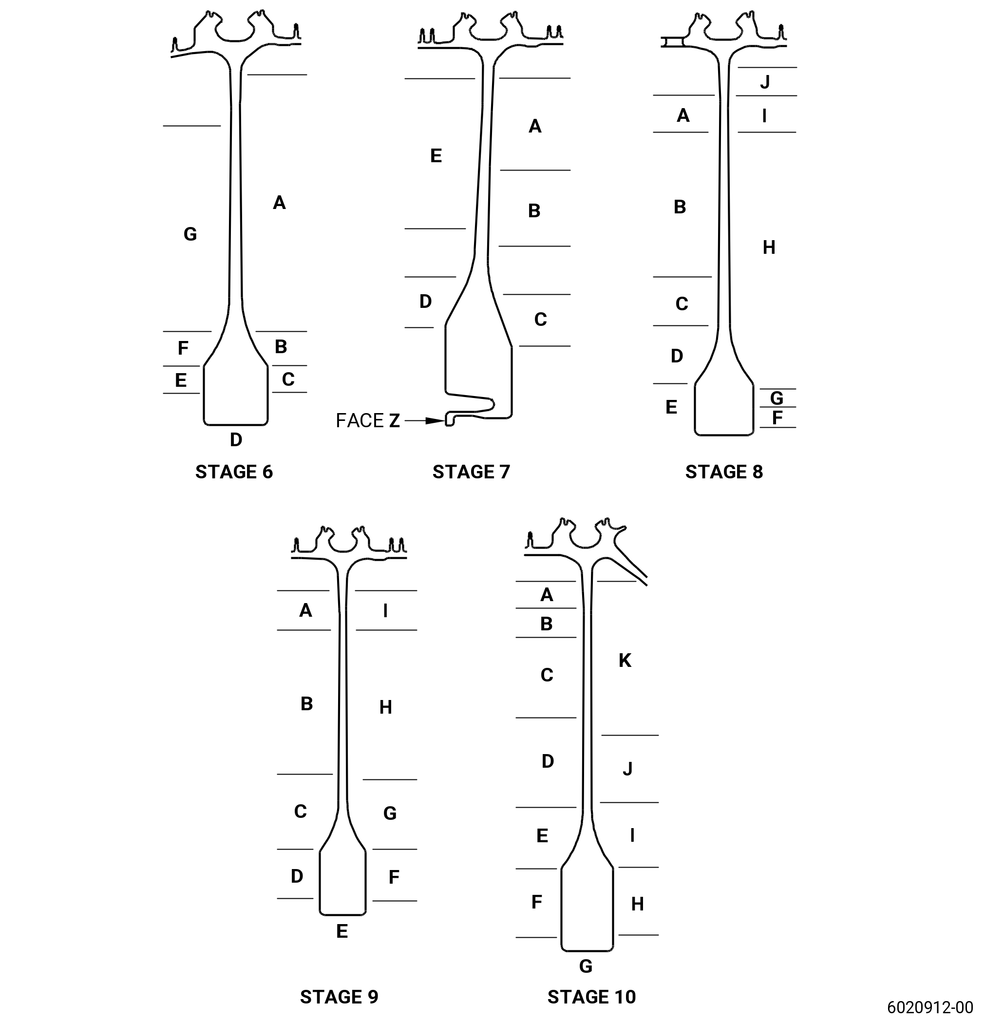
| (2) | For part numbers 2357M30G02: |
| (a) | Scratches on web, hub, web slope, bore surfaces (does not include bore edge corner radius), and stage 7 disk hook (does not include all corner radii, refer to Figure 815): |
| Maximum serviceable limit: |
|
| Repair method: |
|
| (b) | Nicks and dents on web, hub, web slope, bore surfaces (does not include bore edge corner radius), and stage 7 disk hook (does not include all corner radii, refer to Figure 815): |
| Maximum serviceable limit: |
|
| Repair method: |
|
| Subtask 72-31-45-220-152 |
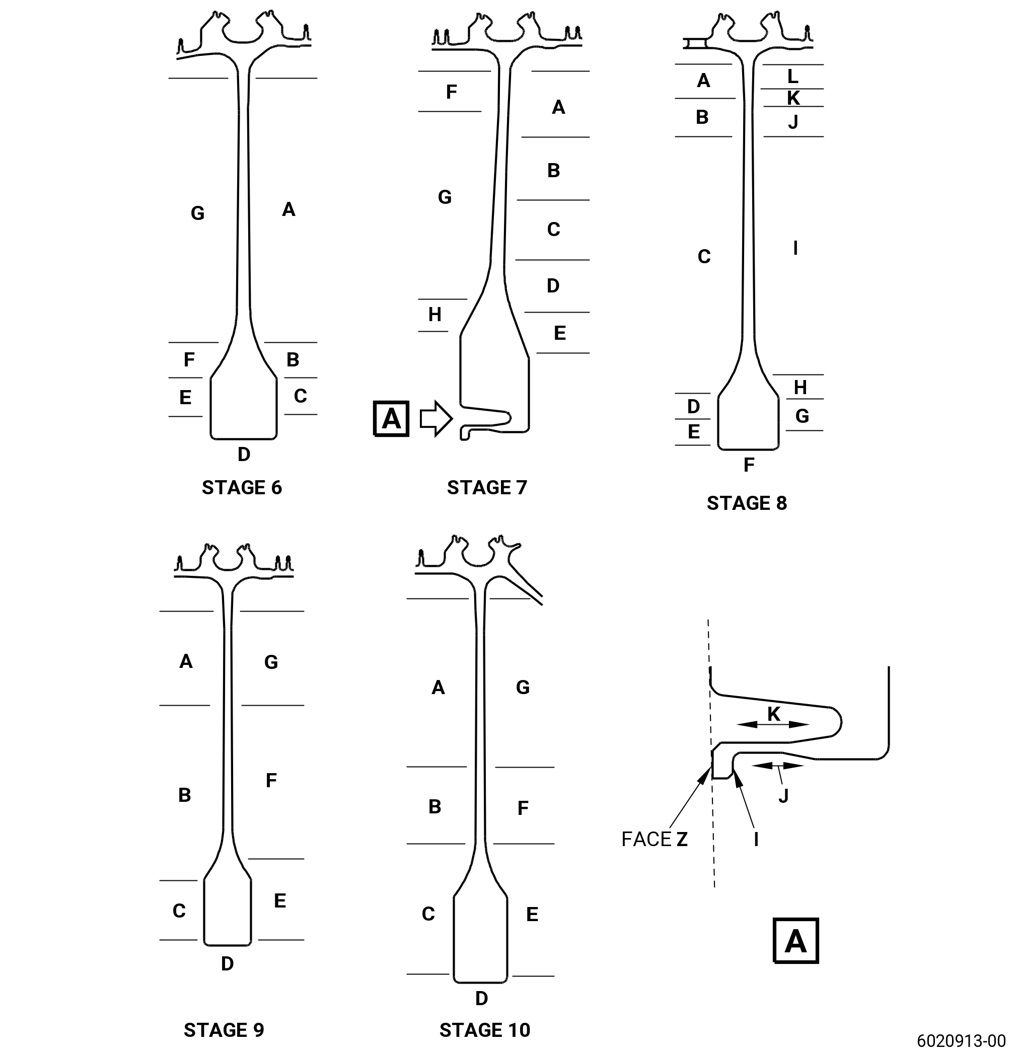
| (3) | For part numbers 2628M56G01 and 2628M56G02 : |
| (a) | Scratches on web, hub, web slope, bore surfaces (bore edge radius included if specified elsewhere): |
| Maximum serviceable limit (for stage 6-10 spool part number 2628M56G01 with part serial numbers listed in GEnx-1B SB 72-0484 Table 2): |
|
| Maximum serviceable limit: |
|
| Repair method: |
|
| (b) | Nicks and dents on web, hub, web slope, bore surfaces (bore edge radius included if specified elsewhere): |
| Maximum serviceable limit (for stage 6-10 spool part number 2628M56G01 with part serial numbers listed in GEnx-1B SB 72-0484 Table 2): |
|
| Maximum serviceable limit: |
|
| Repair method: |
|
| Subtask 72-31-45-220-073 |
| M. | Do an inspection of the disk bores for: |
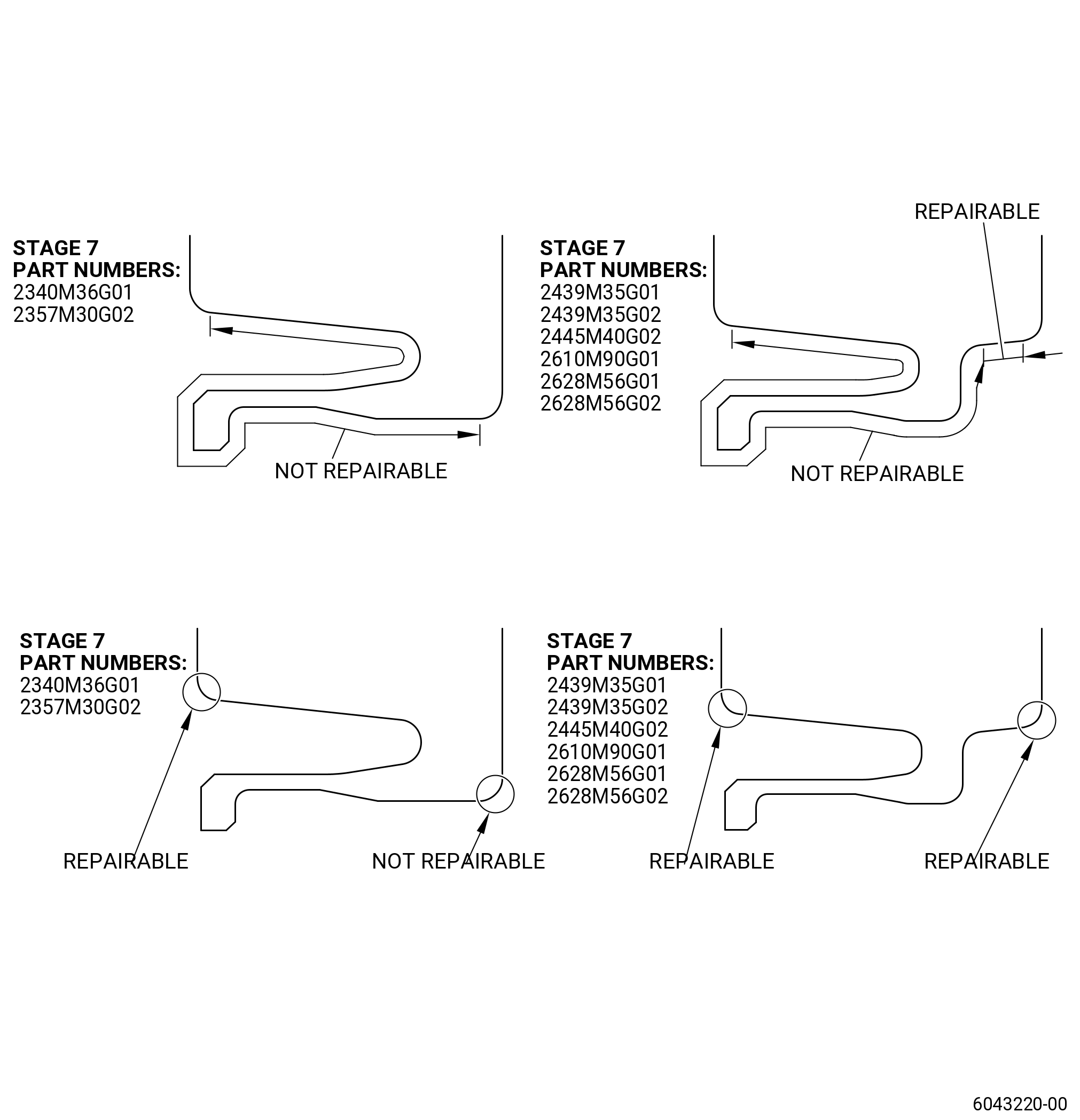
| (1) | Nicks, dents, and scratches (does not include stage 7 disk hook area). Refer to Figure 815. |
| Maximum serviceable limit: |
|
| Maximum repairable limit: |
|
| Repair method: |
|
| Subtask 72-31-45-220-074 |
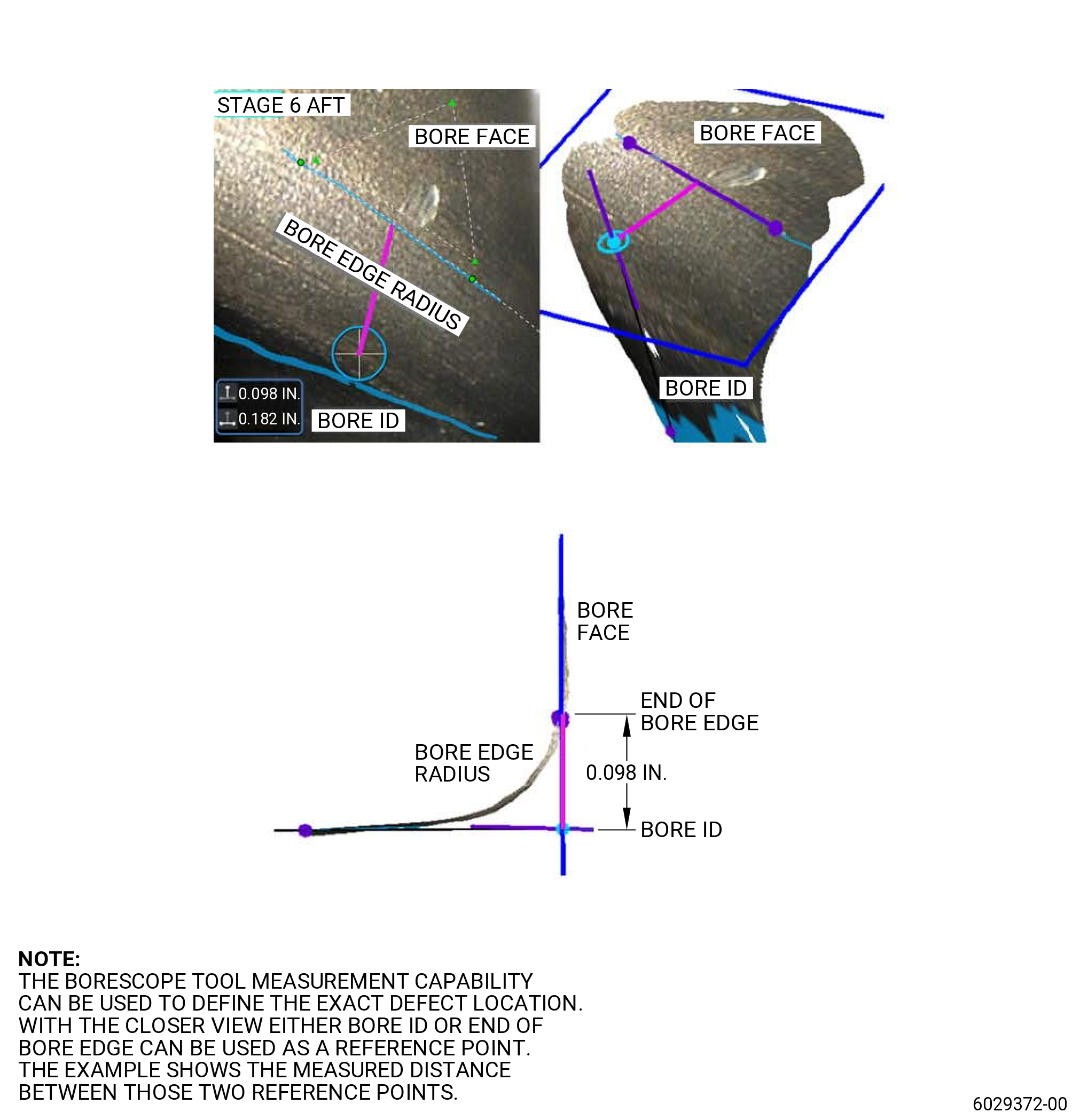
| (2) | Damage in the edge radius. Refer to Figure 815. |
| Maximum serviceable limit: |
|
| Maximum repairable limit: |
|
| Repair method: |
|
| Subtask 72-31-45-220-112 |
| N. | Inspect the wire seal slots for: |
| (1) | Wear on the wire seal slot surfaces at the stage 6 (forward slot and forward face): |
| Maximum serviceable limit: |
|
| Maximum repairable limit: |
|
| Repair method: |
|
| Subtask 72-31-45-220-113 |
| (2) | Wear on the wire seal slot surfaces at the stage 6 (forward slot and aft face): |
| Maximum serviceable limit: |
|
| Maximum repairable limit: |
|
| Repair method: |
|
| Subtask 72-31-45-220-114 |
| (3) | Wear on the wire seal slot surfaces at the stage 6 (aft slot and forward face): |
| Maximum serviceable limit: |
|
| Maximum repairable limit: |
|
| Repair method: |
|
| Subtask 72-31-45-220-115 |
| (4) | Wear on the wire seal slot surfaces at the stage 6 (aft slot and aft face): |
| Maximum serviceable limit: |
|
| Maximum repairable limit: |
|
| Repair method: |
|
| Subtask 72-31-45-220-116 |
| (5) | Wear on the wire seal slot surfaces at the stage 7 (forward slot and forward face): |
| Maximum serviceable limit: |
|
| Maximum repairable limit: |
|
| Repair method: |
|
| Subtask 72-31-45-220-117 |
| (6) | Wear on the wire seal slot surfaces at the stage 7 (forward slot and aft face): |
| Maximum serviceable limit: |
|
| Maximum repairable limit: |
|
| Repair method: |
|
| Subtask 72-31-45-220-118 |
| (7) | Wear on the wire seal slot surfaces at the stage 7 (aft slot and forward face): |
| Maximum serviceable limit: |
|
| Maximum repairable limit: |
|
| Repair method: |
|
| Subtask 72-31-45-220-119 |
| (8) | Wear on the wire seal slot surfaces at the stage 7 (aft slot and aft face): |
| Maximum serviceable limit: |
|
| Maximum repairable limit: |
|
| Repair method: |
|
| Subtask 72-31-45-220-120 |
| (9) | Wear on the wire seal slot surfaces at the stage 8 (forward slot and forward face): |
| Maximum serviceable limit (for stage 6-10 spool part number 2628M56G01 with part serial numbers listed in GEnx-1B SB 72-0484): |
|
| Maximum serviceable limit: |
|
| Maximum repairable limit: |
|
| Repair method: |
|
| Subtask 72-31-45-220-121 |
| (10) | Wear on the wire seal slot surfaces at the stage 8 (forward slot and aft face): |
| Maximum serviceable limit (for stage 6-10 spool part number 2628M56G01 with part serial numbers listed in GEnx-1B SB 72-0484): |
|
| Maximum serviceable limit: |
|
| Maximum repairable limit: |
|
| Repair method: |
|
| Subtask 72-31-45-220-122 |
| (11) | Wear on the wire seal slot surfaces at the stage 8 (aft slot and forward face): |
| Maximum serviceable limit (for stage 6-10 spool part number 2628M56G01 with part serial numbers listed in GEnx-1B SB 72-0484): |
|
| Maximum serviceable limit: |
|
| Maximum repairable limit: |
|
| Repair method: |
|
| Subtask 72-31-45-220-123 |
| (12) | Wear on the wire seal slot surfaces at the stage 8 (aft slot and aft face): |
| Maximum serviceable limit (for stage 6-10 spool part number 2628M56G01 with part serial numbers listed in GEnx-1B SB 72-0484): |
|
| Maximum serviceable limit: |
|
| Maximum repairable limit: |
|
| Repair method: |
|
| Subtask 72-31-45-220-124 |
| (13) | Wear on the wire seal slot surfaces at the stage 9 (forward slot and forward face): |
| Maximum serviceable limit: |
|
| Maximum repairable limit: |
|
| Repair method: |
|
| Subtask 72-31-45-220-125 |
| (14) | Wear on the wire seal slot surfaces at the stage 9 (forward slot and aft face): |
| Maximum serviceable limit: |
|
| Maximum repairable limit: |
|
| Repair method: |
|
| Subtask 72-31-45-220-126 |
| (15) | Wear on the wire seal slot surfaces at the stage 9 (aft slot and forward face): |
| Maximum serviceable limit: |
|
| Maximum repairable limit: |
|
| Repair method: |
|
| Subtask 72-31-45-220-127 |
| (16) | Wear on the wire seal slot surfaces at the stage 9 (aft slot and aft face): |
| Maximum serviceable limit: |
|
| Maximum repairable limit: |
|
| Repair method: |
|
| Subtask 72-31-45-220-128 |
| (17) | Wear on the wire seal slot surfaces at the stage 10 (forward slot and forward face): |
| Maximum serviceable limit: |
|
| Maximum repairable limit: |
|
| Repair method: |
|
| Subtask 72-31-45-220-129 |
| (18) | Wear on the wire seal slot surfaces at the stage 10 (forward slot and aft face): |
| Maximum serviceable limit: |
|
| Maximum repairable limit: |
|
| Repair method: |
|
| Subtask 72-31-45-220-130 |
| (19) | Wear on the wire seal slot surfaces at the stage 10 (aft slot and forward face): |
| Maximum serviceable limit: |
|
| Maximum repairable limit: |
|
| Repair method: |
|
| Subtask 72-31-45-220-131 |
| (20) | Wear on the wire seal slot surfaces at the stage 10 (aft slot and aft face): |
| Maximum serviceable limit: |
|
| Maximum repairable limit: |
|
| Repair method: |
|
| Subtask 72-31-45-220-075 |
| O. | Do an inspection of other surfaces for: |
| (1) | Nicks and scratches: |
| Maximum serviceable limit: |
|
| Repair method: |
|
| Subtask 72-31-45-220-076 |
| (2) | Dents: |
| Maximum serviceable limit: |
|
| Repair method: |
|
| Subtask 72-31-45-220-077 |
| P. | Do an inspection of all areas for: |
| (1) | Discoloration: |
| Maximum serviceable limit: |
|
| Repair method: |
|
| 5 . | Application of Coatings |
| Subtask 72-31-45-350-006 |
| A. | Apply the coating to the spool. Refer to Repair. |
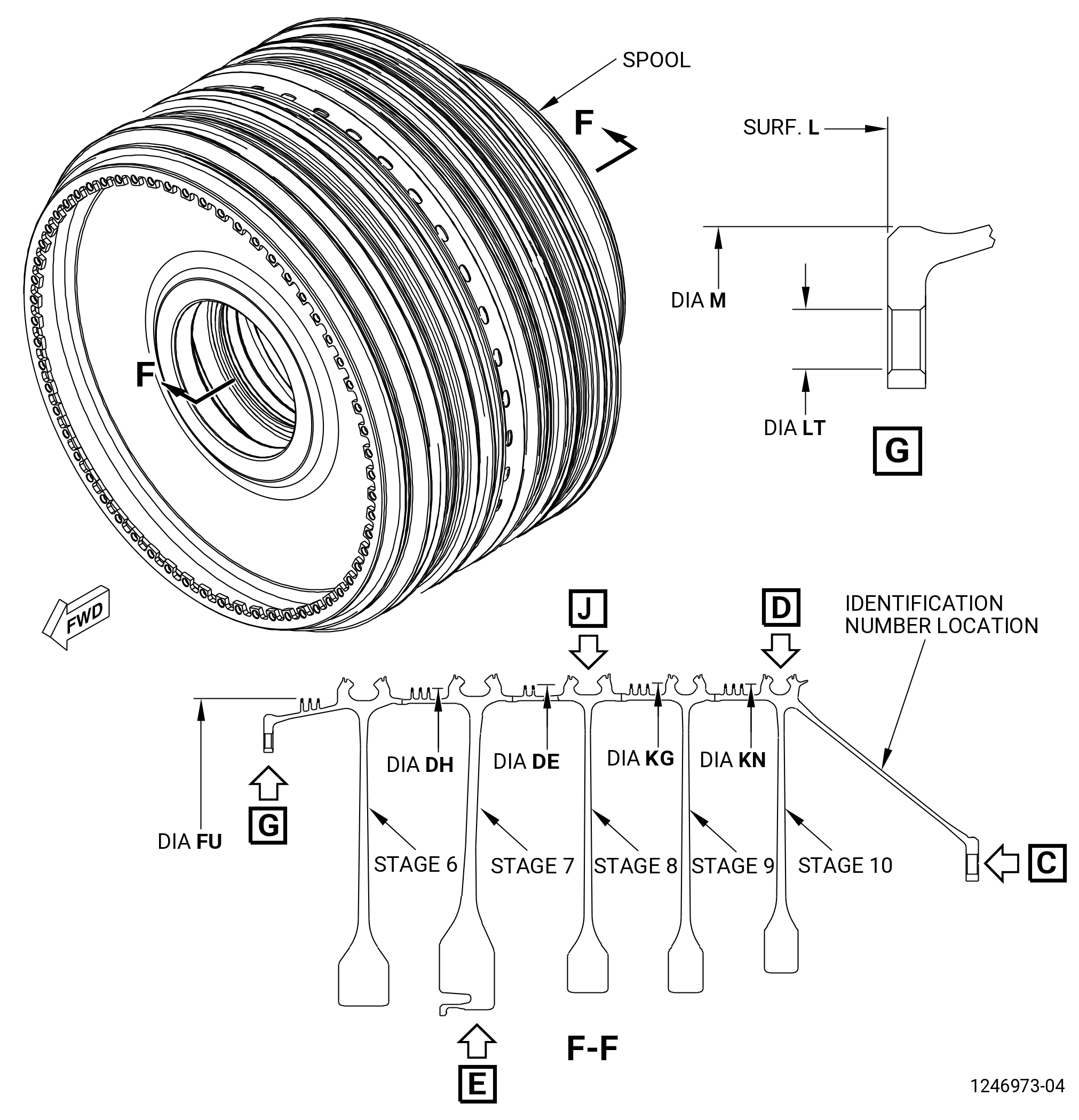
| 6 . | Dimensional Inspection. |
| Refer to Figure 807. |
| Subtask 72-31-45-220-078 |
| A. | Measure each diameter at 10 equally-spaced locations. Calculate the average diameter dimension. Compare the average diameter dimension to the dimension given in the dimensional inspection. |
| NOTE: |
|
| Subtask 72-31-45-220-079 |
| B. | Do an inspection of the diameters as follows: |
| (1) | Diameter B: |
| Minimum serviceable limit: |
|
| Maximum serviceable limit: |
|
| Repair method: |
|
| Subtask 72-31-45-220-098 |
| (2) | Diameter H: |
| Minimum serviceable limit: |
|
| Maximum serviceable limit: |
|
| Repair method: |
|
| Subtask 72-31-45-220-084 |
| (3) | Diameter M: |
| Minimum serviceable limit: |
|
| Maximum serviceable limit: |
|
| Repair method: |
|
| Subtask 72-31-45-220-086 |
| C. | Do an inspection of the interstage seal teeth diameters before you apply the coating for: |
| (1) | Diameter FU: |
| Minimum serviceable limit: |
|
| Maximum serviceable limit: |
|
| Repair method: |
|
| Subtask 72-31-45-220-087 |
| (2) | Diameter DH: |
| Minimum serviceable limit: |
|
| Maximum serviceable limit: |
|
| Repair method: |
|
| Subtask 72-31-45-220-088 |
| (3) | Diameter DE: |
| Minimum serviceable limit: |
|
| Maximum serviceable limit: |
|
| Repair method: |
|
| Subtask 72-31-45-220-089 |
| (4) | Diameter KG: |
| Minimum serviceable limit: |
|
| Maximum serviceable limit: |
|
| Repair method: |
|
| Subtask 72-31-45-220-090 |
| (5) | Diameter KN: |
| Minimum serviceable limit: |
|
| Maximum serviceable limit: |
|
| Repair method: |
|
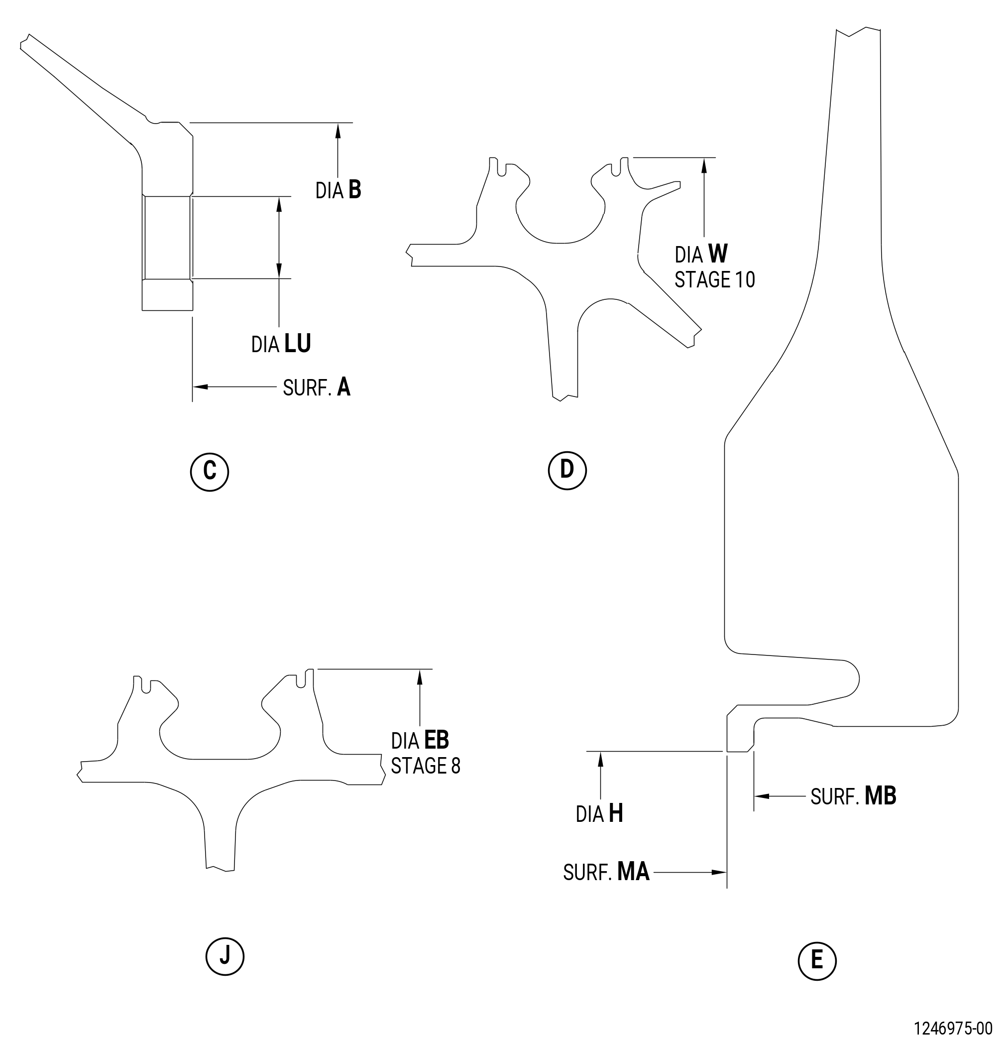
| 7 . | Special Dimensional Inspection. |
| Refer to Figure 807. |
| Subtask 72-31-45-220-091 |
| A. | Do an inspection of diameter W and diameter EB, if an N2 overspeed has occurred, or if you think an overspeed occurred. Contact GE for the initial length of diameter W and diameter EB. |
| Subtask 72-31-45-220-092 |
| B. | Diameter W and diameter EB: |
| Maximum serviceable limit: |
|
| Repair method: |
|
| 8 . | Bolthole Inspection Procedure. |
| Refer to Figure 807. |
| Subtask 72-31-45-350-003 |
| A. | Deleted. |
| Subtask 72-31-45-350-004 |
| A.A. | Deleted. |
| Subtask 72-31-45-220-095 |
| B. | Measure the boltholes as follows: |
| (1) | Diameter LT: |
| Minimum serviceable limit: |
|
| Maximum serviceable limit: |
|
| Repair method: |
|
| (2) | Diameter LU: |
| Minimum serviceable limit: |
|
| Maximum serviceable limit: |
|
| Repair method: |
|
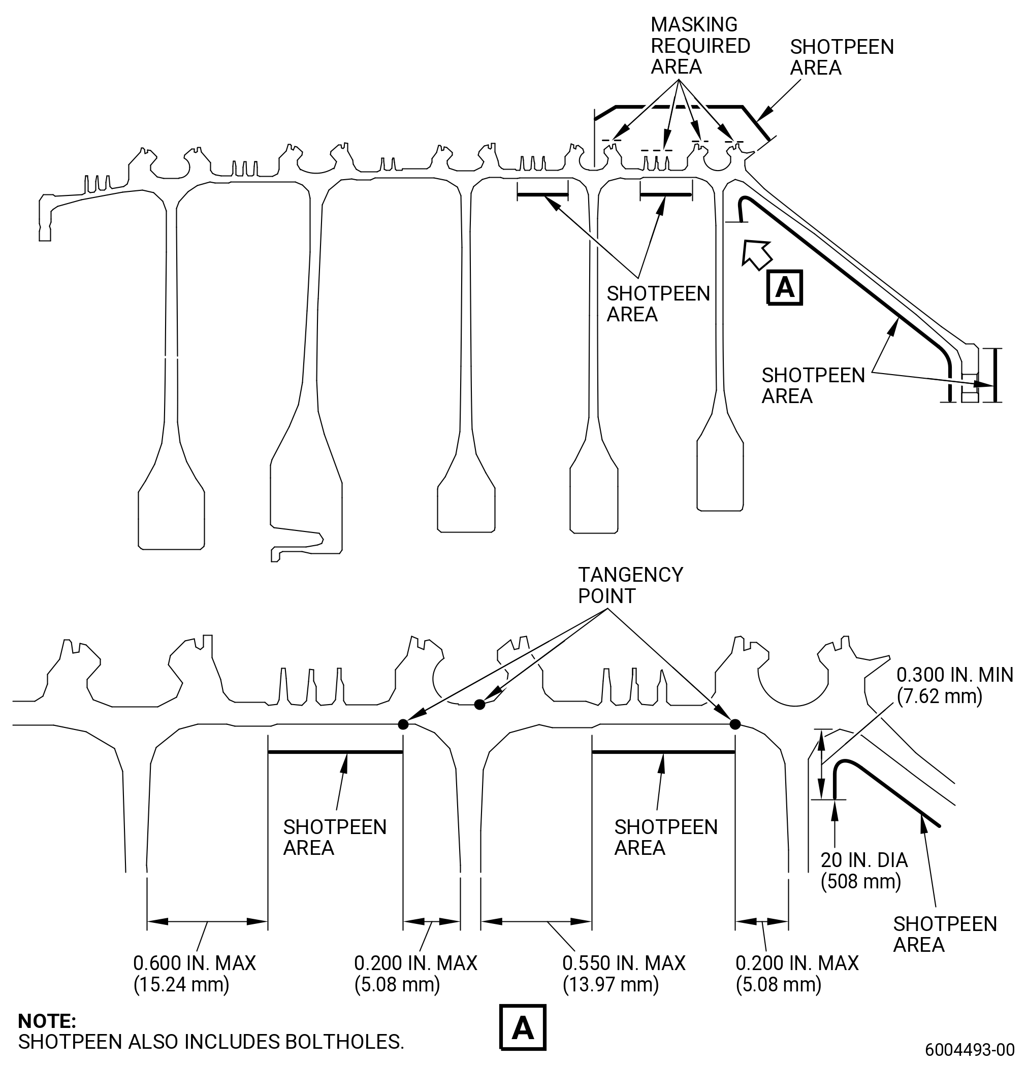
| 9 . | Post Inspection Procedure. |
| Subtask 72-31-45-380-004 |
| A. | Shotpeen the rim region and dovetail post surfaces of the HPC rotor 6-10 spool. Refer to TASK 70-47-01-380-016 (SHOTPEENING), Figure 808, and do as follows: |
| (1) | Apply a mask to the coated areas (rabbets and seal wire grooves at which thermal spray repair. Refer to TASK 72-31-45-300-804 (72-31-45, REPAIR 005) has been completed). |
| (2) | Use C04-166 CCW14 cut wire shot. |
| (3) | Shotpeen to an intensity of 6-12N. |
| (4) | A minimum coverage of 125 percent is necessary. |
| (5) | Verification of intensity is necessary on the peened areas. Use C10-205 test strips. |
| (6) | Overspray is permitted. |
| Subtask 72-31-45-350-015 |
| B. | Re-apply the coating on the interstage seal teeth. Refer to TASK 72-31-45-300-802 (72-31-45, REPAIR 002). |
| 10 . | Tables. |
| Subtask 72-31-45-220-153 |
| NOTE: |
|
| A. | Table 1. |
|
|||||||||||||||||||||||||||||||||||||||||||||||||||||||||||||||||||||||||||||||||||||||||||||||||||||||||||||||||||||||||||||||||||||||||||||||||||||||||||||||||||||||||||||||||||||||||||||||||||||||||||||||||||||||||||||||||||||||||||||||||||||||||||||||||||||||||||||||||||||||||||||||||||||||||||||||||||||||||||||||||||||||||||||||||||||||||||||||||||||||||||||||||||||||||||||||||||||||||||||||||||||||||||||||||||||||||||||||||||||||||||||||||||||||||||||||||||||||||||||||||||||||||||||||||||||||||||||||||||||||||||||||||||||||||||||||||||||||||||||||||||||||||||||||||||||||||||||||||||||||||||||||||||||||||||||||||||||||||||||||||||
| NOTE: |
|
| NOTE: |
|
| B. | Table 2. |
|
||||||||||||||||||||||||||||||||||||||||||||||||||||||||||||||||||||||||||||||||||||||||||||||||||||||||||||||||||||||||||||||||||||||||||||||||||||||||||||||||||||||||||||||||||||||||||||||||||||||||||||||||||||||||||||||||||||||||||||||||||||||||||||||||||||||||||||||||||||||||||||||||||||||||||||||||||||||||||||||||||||||||||||||||||||||||||||||||||||||||||||||||||||||||||||||||||||||||||||||||||||||||||||||||||||||||||||||||||||||||||||||||||||||||||||||||||||||||||||||||||||||||||||||||||||||||||||||||||||||||||||||||||||||||||||||||||||||||||||||||||||||||||||||||||||||||||||||||||||||||||||||||||||||||||||||||||||||||||||||||||||||||||||||||||||||
| NOTE: |
|
| NOTE: |
|
| C. | Table 3. |
|
|||||||||||||||||||||||||||||||||||||||||||||||||||||||||||||||||||||||||||||||||||||||||||||||||||||||||||||||||||||||||||||||||||||||||||||||||||||||||||||||||||||||||||||||||||||||||||||||||||||||||||||||||||||||||||||||||||||||||||||||||||||||||||||||||||||||||||||||||||||||||||||||||||||||||||||||||||||||||||||||||||||||||||||||||||||||||||||||||||||||||||||||||||||||||||||||||||||||||||||||||||||||||||||||||||||||||||||||||||||||||||||||||||||||||||||||||||||||||||||||||||||||||||||||||||||||||||||||||||||||||
| NOTE: |
|
| NOTE: |
|
| D. | Table 4. |
|
||||||||||||||||||||||||||||||||||||||||||||||||||||||||||||||||||||||||||||||||||||||||||||||||||||||||||||||||||||||||||||||||||||||||||||||||||||||||||||||||||||||||||||||||||||||||||||||||||||||||||||||||||||||||||||||||||||||||||||||||||||||||||||||||||||||||||||||||||||||||||||||||||||||||||||||||||||||||||||||||||||||||||||||||||||||||||||||||||||||||||||||||||||||||||||||||||||||||||||||||||||||||||||||||||||||||||||||||||||||||||||||||||||||||||||||||||||||||||||||||||||||||||||||||||||||||||||||||||||||||||||||||||||||||||||||||||||
| NOTE: |
|
| NOTE: |
|
| E. | Table 5. |
|
|||||||||||||||||||||||||||||||||||||||||||||||||||||||||||||||||||||||||||||||||||||||||||||||||||||||||||||||||||||||||||||||||||||||||||||||||||||||||||||||||||||||||||||||||||||||||||||||||||||||||||||||||||||||||||||||||||||||||||||||||||||||||||||||||||||||||||||||||||||||||||||||||||||||||||||||||||||||||||||||||||||||||||||||||||||||||||||||||||||||||||||||||||||||||||||||||||||||||||||||||||||||||||||||||||||||||||||||||||||||||||||||||||||||||||||||||||||||||||||||||||||||||||||||||||||||||||||||||||||||||||||||||||||||||||||||||||||||||||||||||||||||||||||||||||||||
| NOTE: |
|
| NOTE: |
|
| F. | Table 6. |
|
|||||||||||||||||||||||||||||||||||||||||||||||||||||||||||||||||||||||||||||||||||||||||||||||||||||||||||||||||||||||||||||||||||||||||||||||||||||||||||||||||||||||||||||||||||||||||||||||||||||||||||||||||||||||||||||||||||||||||||||||||||||||||||||||||||||||||||||||||||||||||||||||||||||||||||||||||||||||||||||||||||||||||||||||||||||||||||||||||||||||||||||||||||||||||||||||||||||||||||||||||||||||||||||||||||||||||||||||||||||||||||||||||||||||||||||||||||||||||||||||||||||||||||||||||||||||||||||||||||||||||||||||||||||||||||||||||||||||||||||||||||||||||||||||||||||||||||||||||||||||||||||||||||||||||||||||||||||||||||||||||||||||||||||||||||||||||||||||||||||||||||||||||||||||||||||||||||||||
| NOTE: |
|
| NOTE: |
|
| G. | Table 7. |
|
| NOTE: |
|