| GENX-1B CLEANING,INSPECTION,AND REPAIR MANUAL | Dated: 10/31/2019 | |
| CIR 72-31-45 , REPAIR 003 | ||
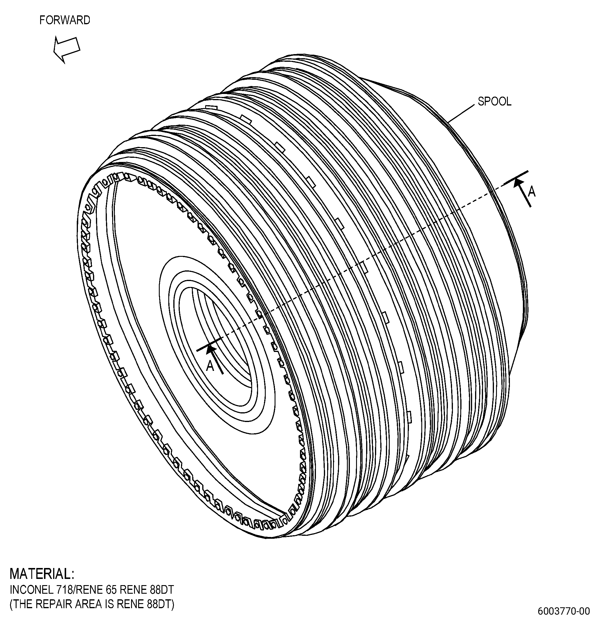
| HIGH PRESSURE COMPRESSOR ROTOR STAGE 6-10 SPOOL - REPAIR - THERMAL SPRAY REPAIR OF THE AFT RABBET | ||
| GENX-1B CLEANING,INSPECTION,AND REPAIR MANUAL | Dated: 10/31/2019 | |
| CIR 72-31-45 , REPAIR 003 | ||
| HIGH PRESSURE COMPRESSOR ROTOR STAGE 6-10 SPOOL - REPAIR - THERMAL SPRAY REPAIR OF THE AFT RABBET | ||
| * * * FOR ALL |
| TASK 72-31-45-300-803 |
| 1 . | Thermal Spray Repair of The Aft Rabbet. |
| A. | This procedure gives instructions to repair the high pressure compressor rotor stage 6-10 spool (spool) by thermal spraying the aft rabbet. Refer to Figure 901. |
| B. | The following maximum repairable limits apply to this repair: |
| NOTE: |
|
| (4) | Visual Inspection. |
| (d) | Do an inspection of the aft rabbet for: |
| 1 | Nicks, dents, and scratches: |
| Maximum repairable limit: |
|
| 2 | Fretting, galling, or wear: |
| Maximum repairable limit: |
|
| 3 | Corrosion pits: |
| Maximum repairable limit: |
|
| C. | The subsequent table gives a list of the part numbers that are applicable to this procedure. All part numbers are applicable to all paragraphs unless specified differently. |
|
||||||||||||||||||||||||||||||||||||
| D. | Proprietary/Complex Process Statement. |
| (1) | None. |
| 2 . | Tools, Equipment, and Materials. |
| NOTE: |
|
| A. | Tools and Equipment. |
| (1) | Special Tools. None. |
| (2) | Standard Tools and Equipment. None. |
| (3) | Locally Manufactured Tools. None. |
| B. | Consumable Materials. |
| C. | Referenced Procedures. |
|
| D. | Expendable Parts. None. |
| E. | SPD Information. |
| (1) | Spares Supplied. None. |
| (2) | Protected Spares. None. |
| (3) | Locally Manufactured Spares. None. |
| F. | Special Solutions. None. |
| G. | Test Specimens. None. |
| 3 . | Dimensional Information. |
| Subtask 72-31-45-220-134 |
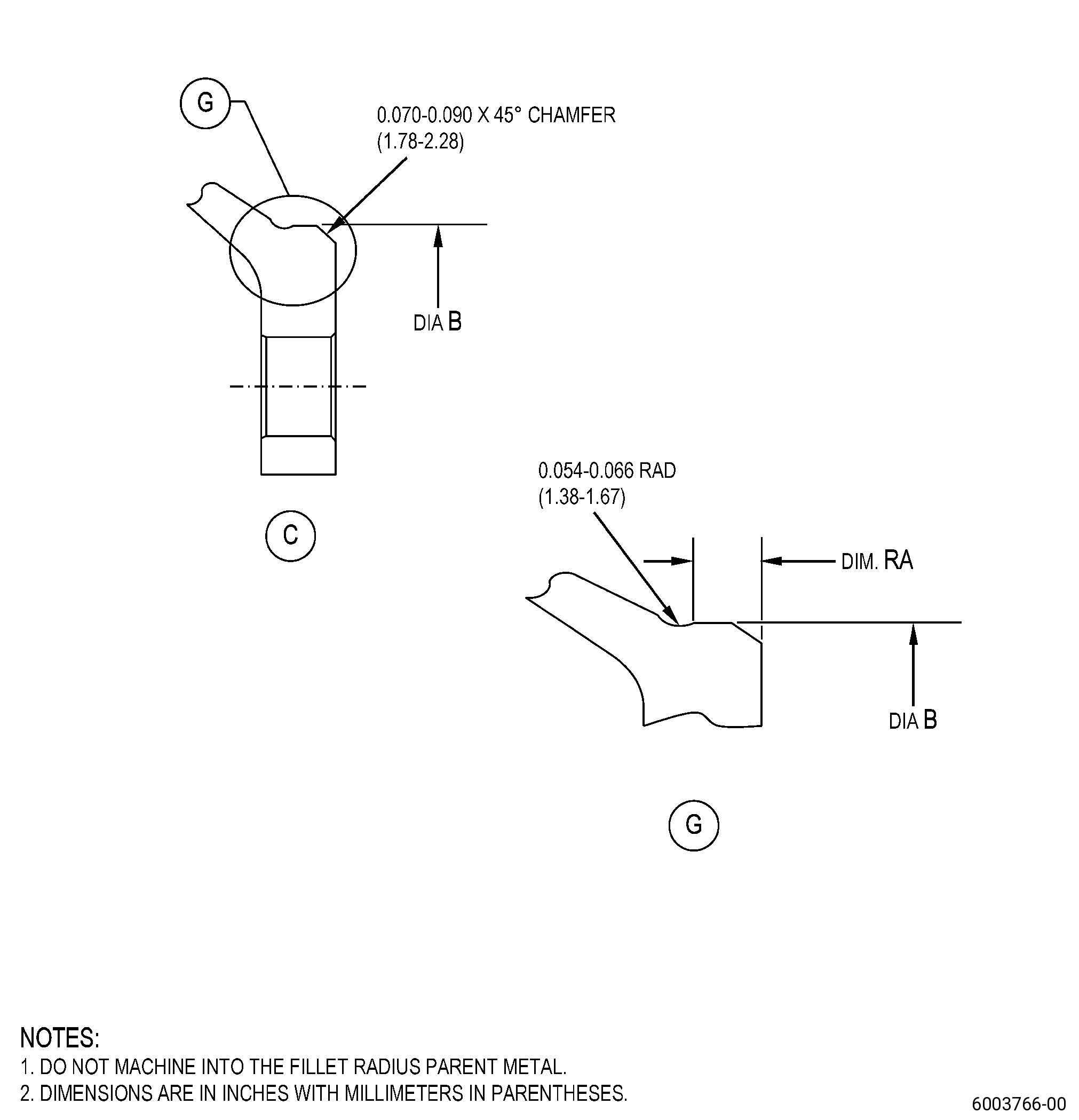
| A. | Refer to Figure 901 for specified dimensions and locations. |
| NOTE: |
|
| NOTE: |
|
|
| 4 . | Setup Information. |
| Subtask 72-31-45-350-016 |
| A. | Set-up the spool for machining and shotpeening. Refer to Figure 901 and as follows: |
| (1) | Install the spool in the holding fixture. |
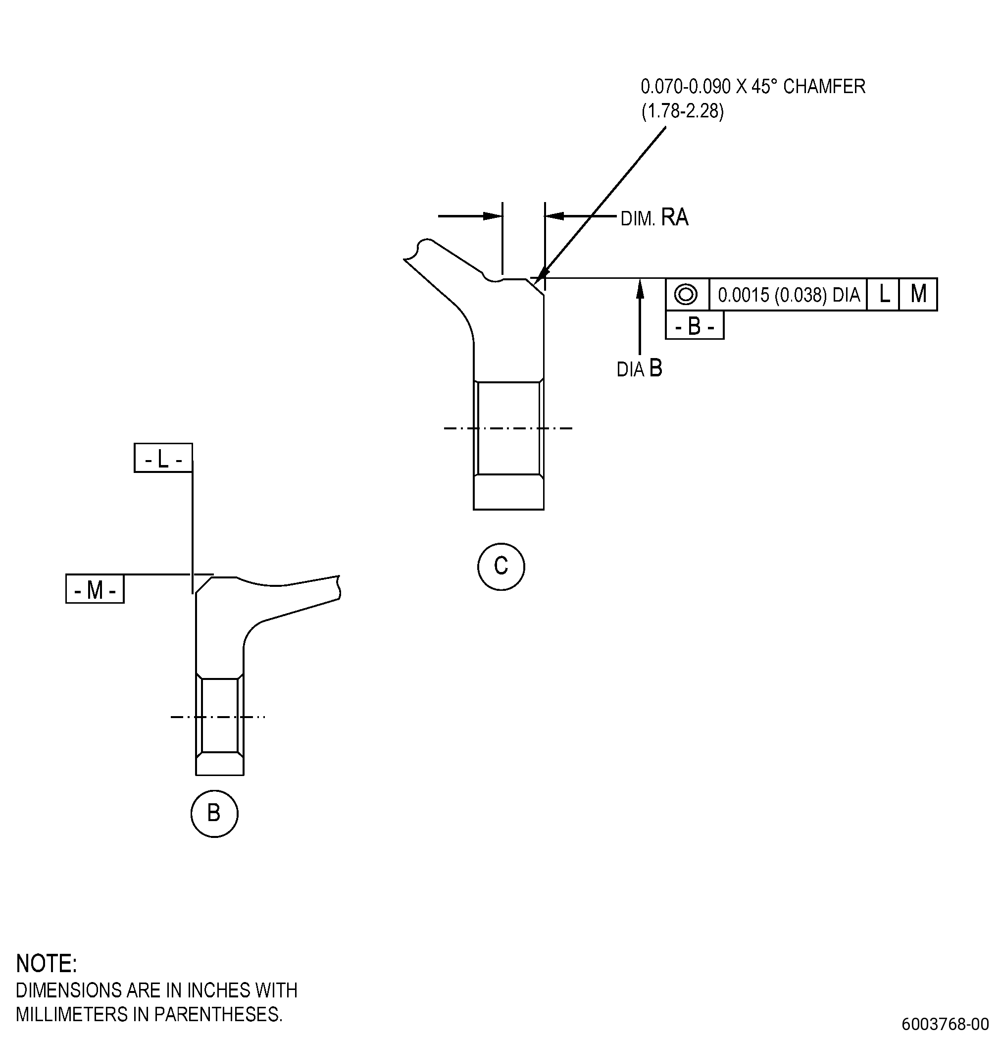
| (2) | Surface L must be flat to 0.001 inch (0.02 mm) or less. |
| (3) | Diameter M must have a runout of 0.001 inch (0.02 mm) or less. |
| 5 . | Procedure. |
| Subtask 72-31-45-160-003 |
| A. | Clean the spool. Refer to TASK 70-21-00-110-051 (CHEMICAL CLEANING), TASK 70-21-03-160-001 (CLEANING METHOD NO. 3 - STEAM CLEANING). |
| Subtask 72-31-45-220-135 |
| B. | Do a visual inspection of the spool marking area for indication of repairs done before. Refer to Figure 901 and as follows: |
| (1) | If you find the mark R003, the spool was thermal spray (HVOF) repaired. You cannot repair the spool again with this repair. |
| Subtask 72-31-45-220-136 |
| C. | Do a visual and dimensional inspection of the spool diameter B. Refer to Subtask 72-31-45-220-134 (paragraph 3.A.) and as follows: |
| (1) | If diameter B is less than the minimum in-process limits, you cannot repair the spool with this repair. |
| (2) | If diameter B is more than the minimum finish dimension and there is wear or visual indications on diameter B, machine diameter B to the minimum finish dimensions to remove the indications. Refer to Subtask 72-31-45-320-006 (paragraph 5.D.). |
| (3) | If you cannot remove the indications on diameter B to the minimum finish dimension, machine diameter B to the in-process dimensions. Refer to Subtask 72-31-45-320-006 (paragraph 5.D.). |
| Subtask 72-31-45-320-006 |
| D. | Machine the spool diameter B. Refer to TASK 70-00-03-800-004 (MACHINING DATA), Subtask 72-31-45-220-134 (paragraph 3.A.), Figure 901, Figure 902, and as follows: |
| (1) | Set-up the spool for machining. Refer to Subtask 72-31-45-350-016 (paragraph 4.A.). |
| CAUTION: |
|
| (2) | Machine diameter B to remove all the distressed metal and/or prepare it to thermal-spray as follows: |
| (a) | If you can remove the distressed material to the finish dimensional limits of diameter B, thermal-spray is not necessary. Machine diameter B to the finish dimensions. |
| (b) | If you cannot remove the distressed material to the finish dimensional limits of diameter B, thermal-spray is necessary. Machine diameter B to the in-process dimensions. |
| Subtask 72-31-45-320-007 |
| (c) | Machine the spool with the parameters that follow: |
| NOTE: |
|
| 1 | The maximum uniform tool flank wear must be 0.012 inch (0.30 mm). |
| 2 | The maximum speed must be 80 SFM (surface feet for each minute). |
| 3 | The maximum feed must be 0.005 IPR (inch for each revolution) (0.12 mm for each revolution). |
| 4 | The final pass depth of cut must be 0.002-0.006 inch (0.06-0.15 mm). |
| 5 | The flood of coolant must be continuous. |
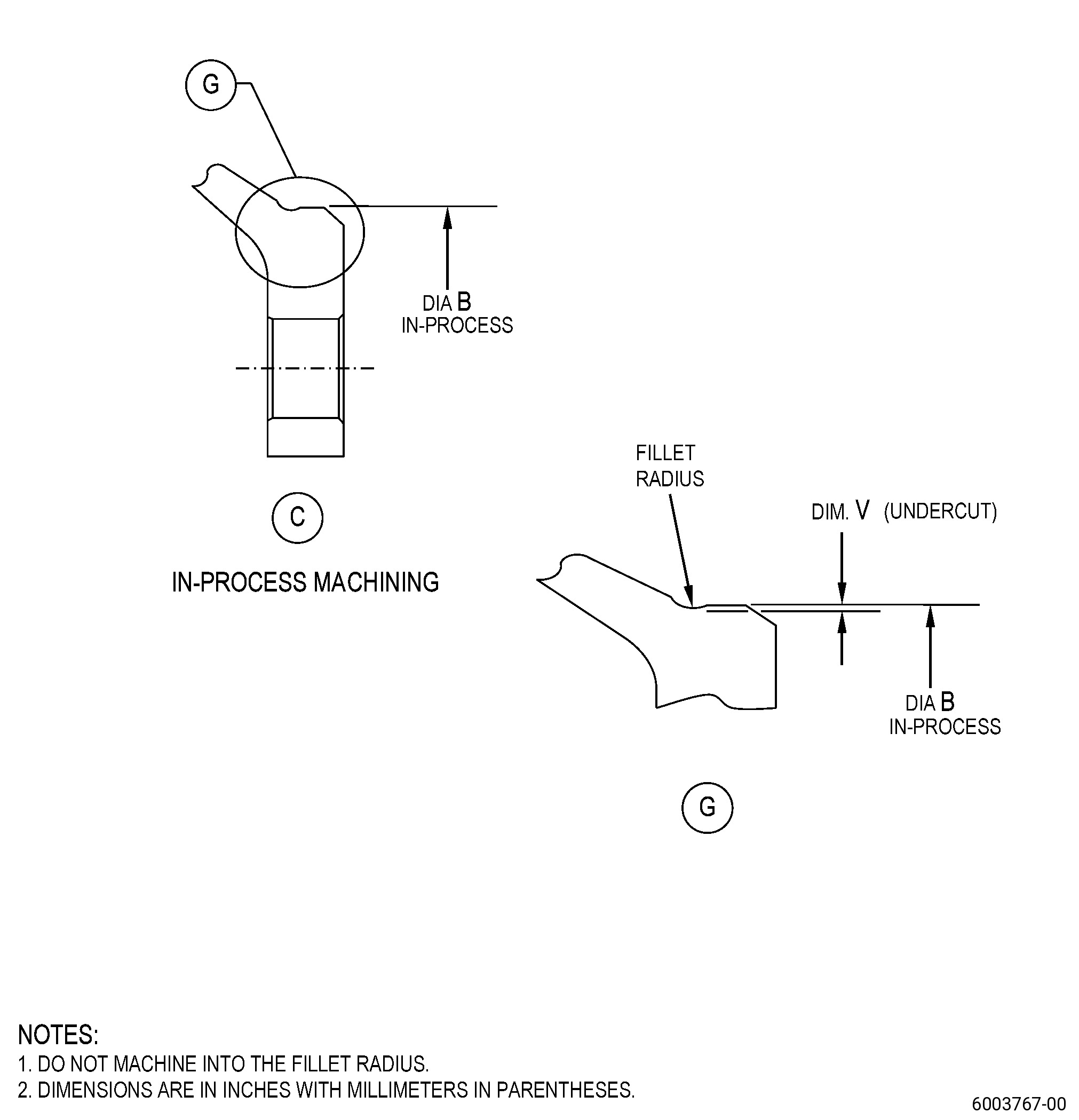
| (d) | Use the information from dimension V to set the machining tool and to calculate the depth of cut, and as follows: |
| 1 | Dimension V must be 0.001 inch (0.03 mm) minimum. |
| Subtask 72-31-45-350-017 |
| (3) | If necessary, blend the spool. Refer to TASK 70-42-00-350-002 (BLENDING AND REMOVAL OF HIGH METAL PROCEDURES), and as follows: |
| (a) | Remove the burrs and rolled edges. |
| (b) | Break edges to 0.010 inch (0.25 mm) maximum. |
| Subtask 72-31-45-110-012 |
| E. | Etch the spool diameter B. Refer to TASK 70-24-00-110-033 (ETCHING PROCEDURES FOR FLUORESCENT-PENETRANT INSPECTION), TASK 70-24-01-110-034 (SWAB ETCHING PROCEDURE), and as follows: |
| (1) | Use Class C or Class G etchant. |
| Subtask 72-31-45-230-004 |
| F. | Do an inspection of the spool diameter B. Refer to TASK 70-32-00-200-002 (INDIRECT INSPECTION METHODS), TASK 70-32-03-230-002 (SPOT-FLUORESCENT-PENETRANT INSPECTION), and as follows: |
| (1) | Use Class G penetrant. |
| (2) | Refer to TASK 72-31-45-200-807 (72-31-45, INSPECTION 001), for the fluorescent-penetrant inspection limits. |
| Subtask 72-31-45-100-009 |
| G. | Clean the spool. Refer to TASK 70-21-00-110-051 (CHEMICAL CLEANING), TASK 70-21-03-160-001 (CLEANING METHOD NO. 3 - STEAM CLEANING). |
| Subtask 72-31-45-380-005 |
| H. | Peen the spool repair area. Refer to TASK 70-47-01-380-016 (SHOTPEENING), and do as follows: |
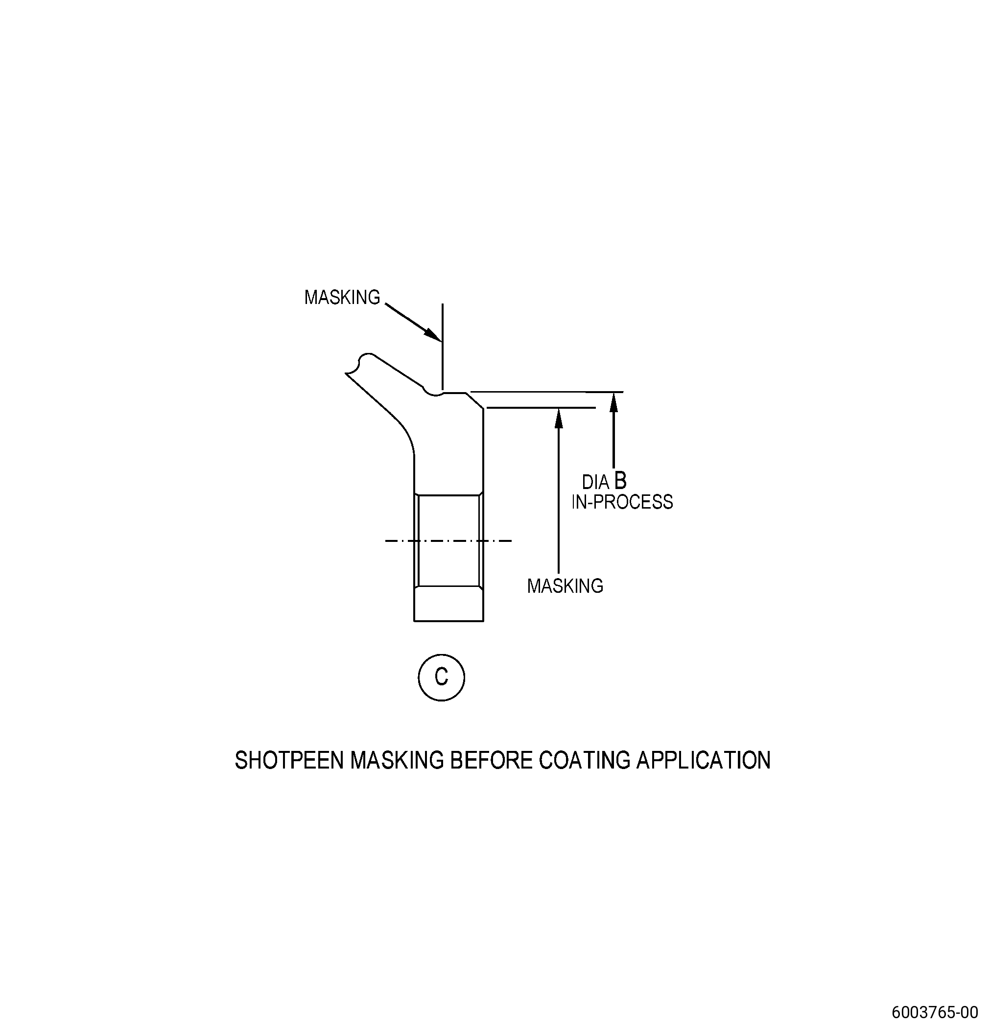
| (1) | Apply C10-021 plastic tape to all areas that you will not peen. Refer to Figure 903. |
| Subtask 72-31-45-350-018 |
| (2) | Set-up the spool for shotpeening. Refer to Subtask 72-31-45-350-016 (paragraph 4.A.) and as follows: |
| (a) | The runout of surface L and diameter M must be 0.050 inch (1.27 mm) maximum. |
| (3) | Use C10-205 almen N test strips. |
| (4) | Use C04-166 CCW14 steel shot with an intensity of 0.006-0.012N. |
| (5) | Coverage must be a minimum of 125 percent. |
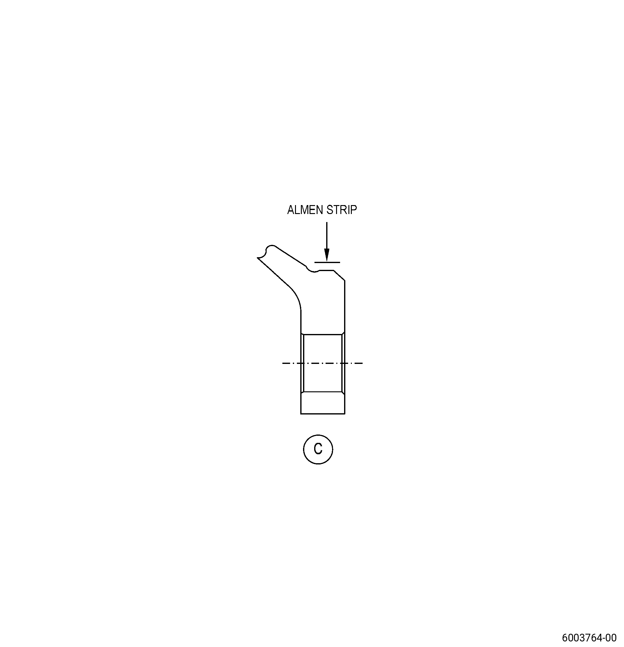
| (6) | Intensity verification is necessary in the repair area. Refer to Figure 904. |
| (7) | Remove the plastic tape. |
| Subtask 72-31-45-340-005 |
| WARNING: |
|
| I. | Thermal-spray the spool and test specimens. Refer to TASK 70-49-00-340-001 (THERMAL SPRAYING), TASK 70-49-36-340-038 (HIGH DENSITY INCONEL 718 COATING APPLIED BY HVOF THERMAL SPRAY), Subtask 72-31-45-220-134 (paragraph 3.A.), Figure 901, and do as follows: |
| CAUTION: |
|
| NOTE: |
|
| (1) | Grit-blast the spool diameter B and the test specimens as follows: |
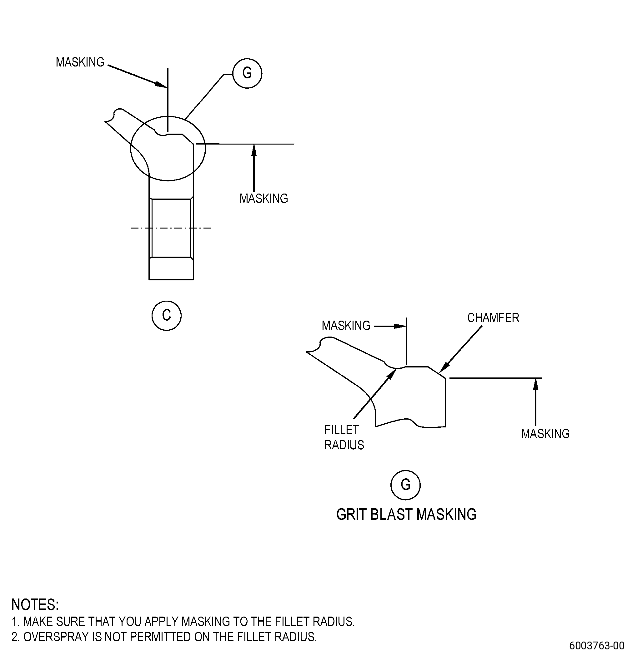
| (a) | Apply C10-012 masking tape to the spool. Refer to Figure 905. |
| (b) | The final roughness average must be consistent with a nickel base superalloy. |
| (c) | Grit blast overspray on the fillet radius is not permitted. |
| CAUTION: |
|
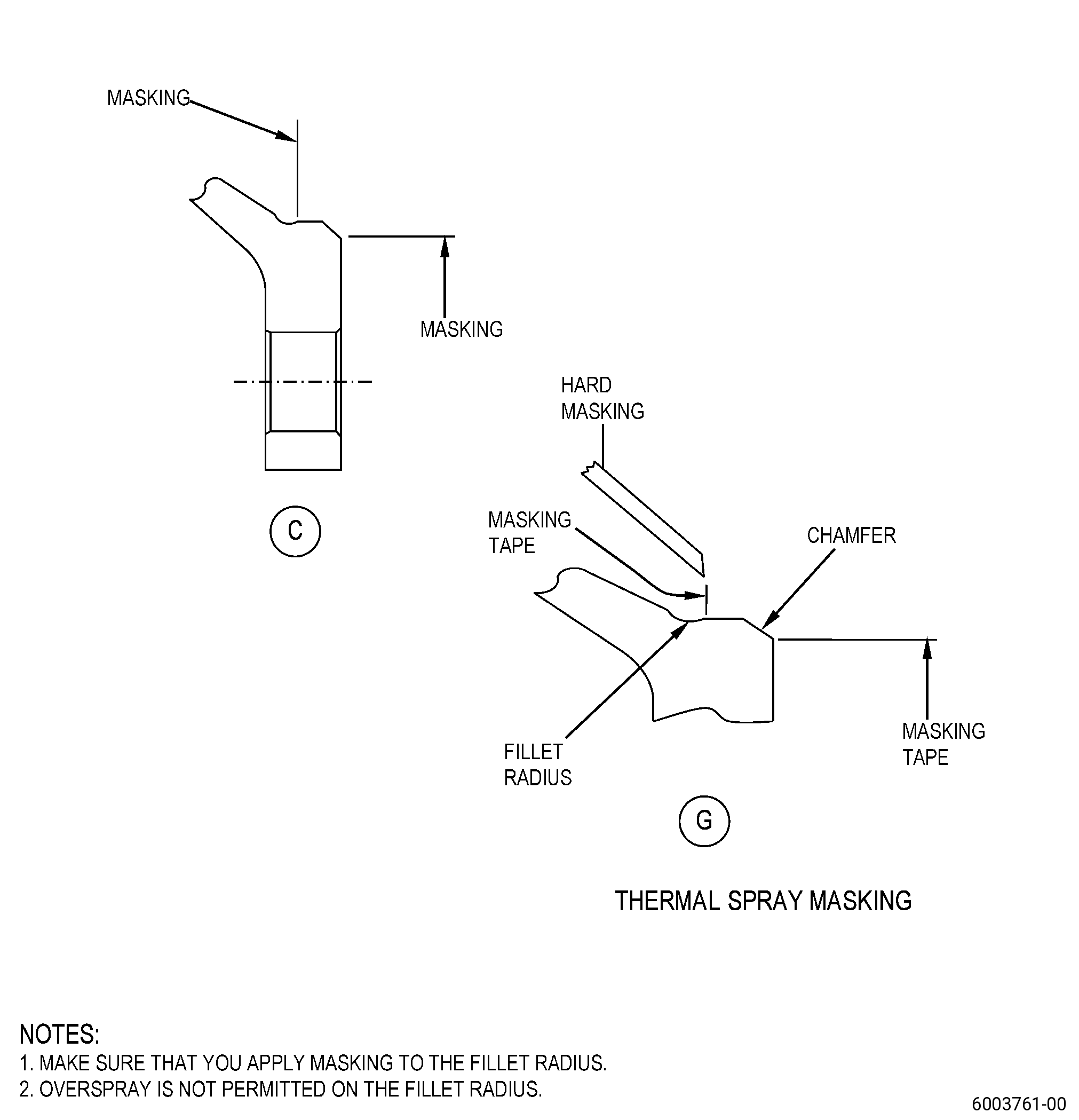
| (2) | Apply masking to the spool with a combination of C10-012 masking tape and hard masking as follows: |
| NOTE: |
|
| (a) | Make sure that you keep the clearance between the hard masking and the C10-012 masking tape to a minimum to prevent that the HVOF stream does not remove the C10-012 masking tape. |
| Subtask 72-31-45-160-004 |
| WARNING: |
|
| (3) | Clean the repair area and the test specimens as follows: |
| (a) | Use a C10-182 cleaning cloth moist with C04-035 isopropyl alcohol or C04-003 acetone to wipe the repair area. |
| (b) | Replace each dirty cleaning cloth with a new C10-182 cleaning cloth until the last moist cleaning cloth stays clean. |
| Subtask 72-31-45-340-006 |
| CAUTION: |
|
| (4) | Apply thermal spray coating to diameter B and to the test specimens. Refer to Subtask 72-31-45-220-134 (paragraph 3.A.) and as follows: |
| NOTE: |
|
| (a) | The thermal spray coating thickness must be 0.003-0.040 inch (0.08-1.01 mm). |
| (b) | Overspray is not permitted. |
| (5) | Do all quality assurance testing specified in TASK 70-49-36-340-038 (HIGH DENSITY INCONEL 718 COATING APPLIED BY HVOF THERMAL SPRAY). |
| CAUTION: |
|
| (6) | Remove all the masking. |
| Subtask 72-31-45-320-008 |
| J. | Machine the spool diameter B to the finish dimensions. Refer to TASK 70-00-03-800-004 (MACHINING DATA), Figure 901, Figure 902, and as follows: |
| NOTE: |
|
| (1) | Set-up the spool for machining. Refer to Subtask 72-31-45-350-016 (paragraph 4.A.). |
| CAUTION: |
|
| (2) | Machine diameter B to the finish dimensions. Refer to Subtask 72-31-45-220-134 (paragraph 3.A.). |
| (3) | Surface finish must be 90 microinches (2.2 micrometers) or better. |
| (4) | Machine the thermal spray coating on the rabbet aft end to repair the chamfer initial contour. |
| (5) | Break edges 0.005-0.015 inch (0.13-0.38 mm). |
| Subtask 72-31-45-220-137 |
| (6) | Do a visual inspection of the machined coating as follows: |
| (a) | Spalling, flaking, or cracking of the coating is not permitted. |
| Subtask 72-31-45-100-011 |
| K. | Clean the spool. Refer to TASK 70-21-00-110-051 (CHEMICAL CLEANING), and TASK 70-21-03-160-001 (CLEANING METHOD NO. 3 - STEAM CLEANING). |
| Subtask 72-31-45-350-019 |
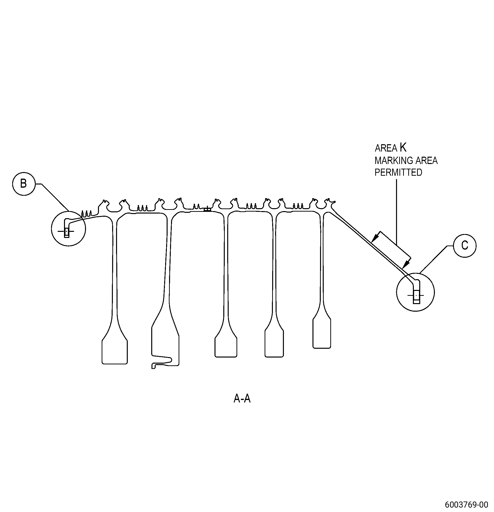
| L. | Put the mark R003 in the spool area K near the part number or serial number. Refer to TASK 70-16-00-350-001 (MARKING PRACTICES), TASK 70-16-08-350-001 (DOT PEEN MARKING FOR OPTICAL CHARACTER RECOGNITION), Figure 901, and as follows: |
| NOTE: |
|
| (1) | Use method number 2 Intermediate. |
| (2) | Do not put a mark less than 0.05 inch (1.3 mm) from an edge or a radius. |
| (3) | This mark is only necessary if you thermal sprayed the spool. If you did not thermal-spray the spool, do not put a mark in area K. |
| Subtask 72-31-45-220-138 |
| M. | Do a dimensional inspection of the spool diameter B. Refer to Subtask 72-31-45-220-134 (paragraph 3.A.), Figure 901, and as follows: |
| (1) | Diameter B must agree with the finish dimensions. |
| (2) | Make sure that the concentricity of diameter B with respect to datum L and datum M is 0.0015 inch (0.038 mm) or less. |
| Subtask 72-31-45-220-139 |
| N. | Do a final inspection of the spool. Refer to TASK 72-31-45-200-807 (72-31-45, INSPECTION 001). |