| GENX-1B CLEANING,INSPECTION,AND REPAIR MANUAL | Dated: 03/02/2020 | |
| CIR 72-31-45 , REPAIR 001 | ||
| HIGH PRESSURE COMPRESSOR ROTOR STAGE 6-10 SPOOL - REPAIR - THERMAL SPRAY REPAIR OF FORWARD RABBET | ||
| GENX-1B CLEANING,INSPECTION,AND REPAIR MANUAL | Dated: 03/02/2020 | |
| CIR 72-31-45 , REPAIR 001 | ||
| HIGH PRESSURE COMPRESSOR ROTOR STAGE 6-10 SPOOL - REPAIR - THERMAL SPRAY REPAIR OF FORWARD RABBET | ||
| * * * FOR ALL |
| TASK 72-31-45-300-801 |
| 1 . | Repair for the High Pressure Compressor Rotor Stage 6-10 Spool. |
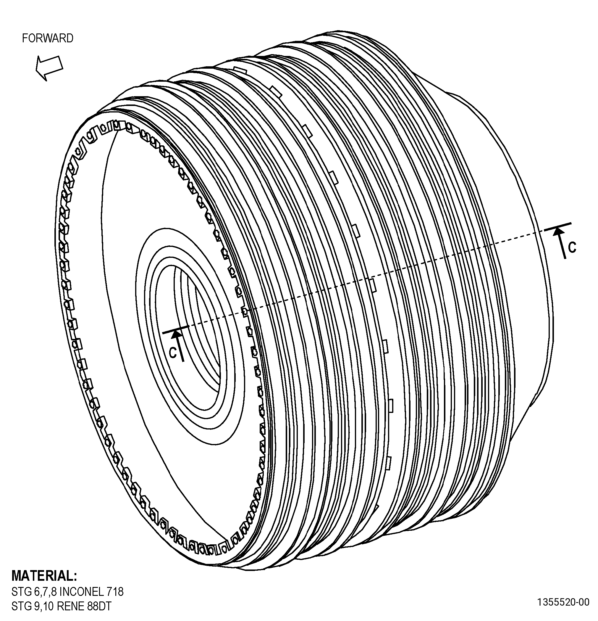
| A. | This procedure gives instructions to repair the forward rabbet of the high pressure compressor rotor stage 6-10 spool (spool) with a thermal spray repair. Refer to Figure 901. |
| B. | The following maximum repairable limits apply to this repair: |
| NOTE: |
|
| NOTE: |
|
| (4) | Visual Inspection. |
| (c) | Do an inspection of the forward rabbet for: |
| 1 | Nicks, dents, and scratches on parent metal: |
| Maximum repairable limit: |
|
| 2 | Fretting, galling, or wear on parent metal: |
| Maximum repairable limit: |
|
| 3 | Corrosion pits on parent metal: |
| Maximum repairable limit: |
|
| 4 | Chipped or missing HVOF or APS coating: |
| Maximum repairable limit: |
|
| (6) | Dimensional Inspection: |
| (b) | Do an inspection of the diameters as follows: |
| 3 | Diameter M: |
| Maximum repairable limit: |
|
| C. | The subsequent table gives a list of the part numbers that are applicable to this repair. All part numbers are applicable to all paragraphs unless specified differently. |
|
||||||||||||||||||||||||||||||||||||
| D. | Proprietary/Complex Process Statement. |
| (1) | None. |
| 2 . | Tools, Equipment, and Materials. |
| NOTE: |
|
| A. | Tools and Equipment. |
| (1) | Special Tools. None. |
| (2) | Standard Tools and Equipment. None. |
| (3) | Locally Manufactured Tools. None. |
| B. | Consumable Materials. |
| C. | Referenced Procedures. |
|
| D. | Expendable Parts. None. |
| E. | SPD Information. None. |
| F. | Special Solutions. None. |
| G. | Test Specimens. Refer to TASK 70-49-32-340-033 (THERMAL SPRAYING INCONEL 718 (POWDER)) . |
| 3 . | Dimensional Information. |
| Subtask 72-31-45-220-102 |
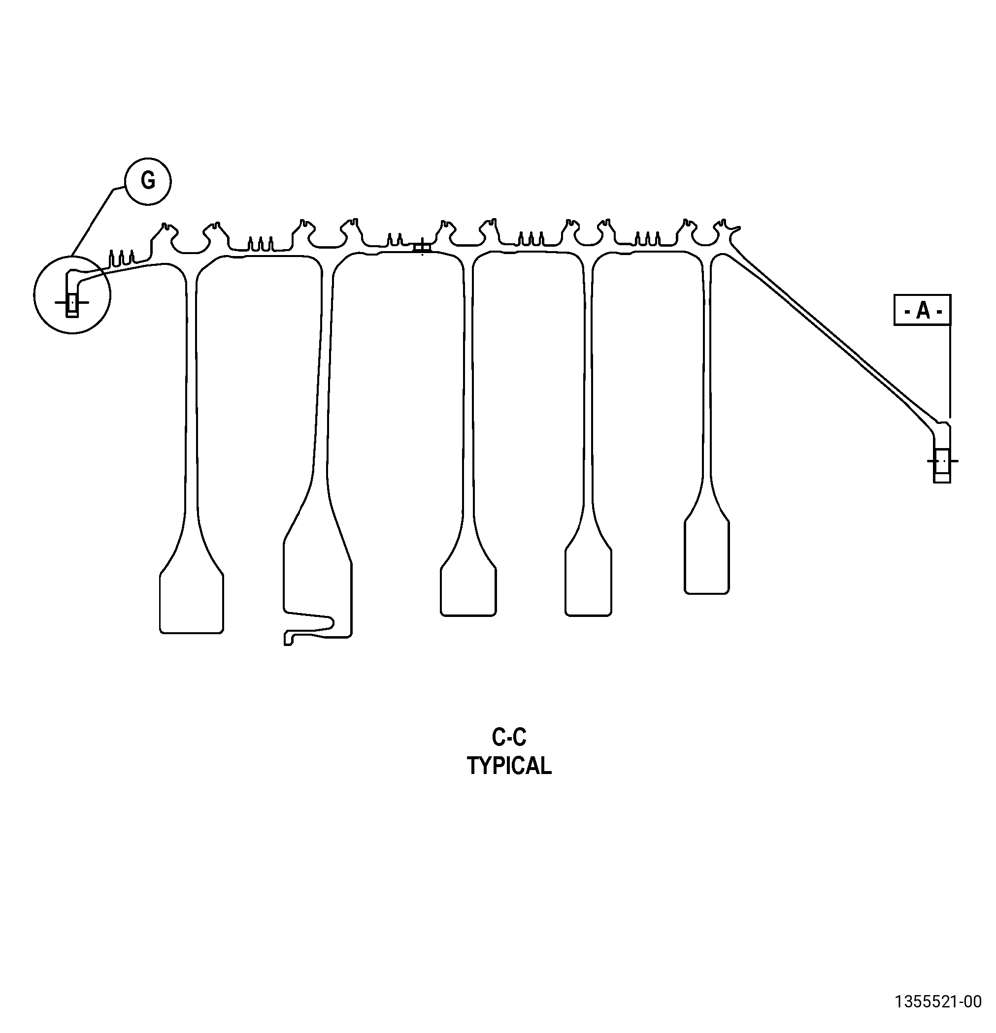
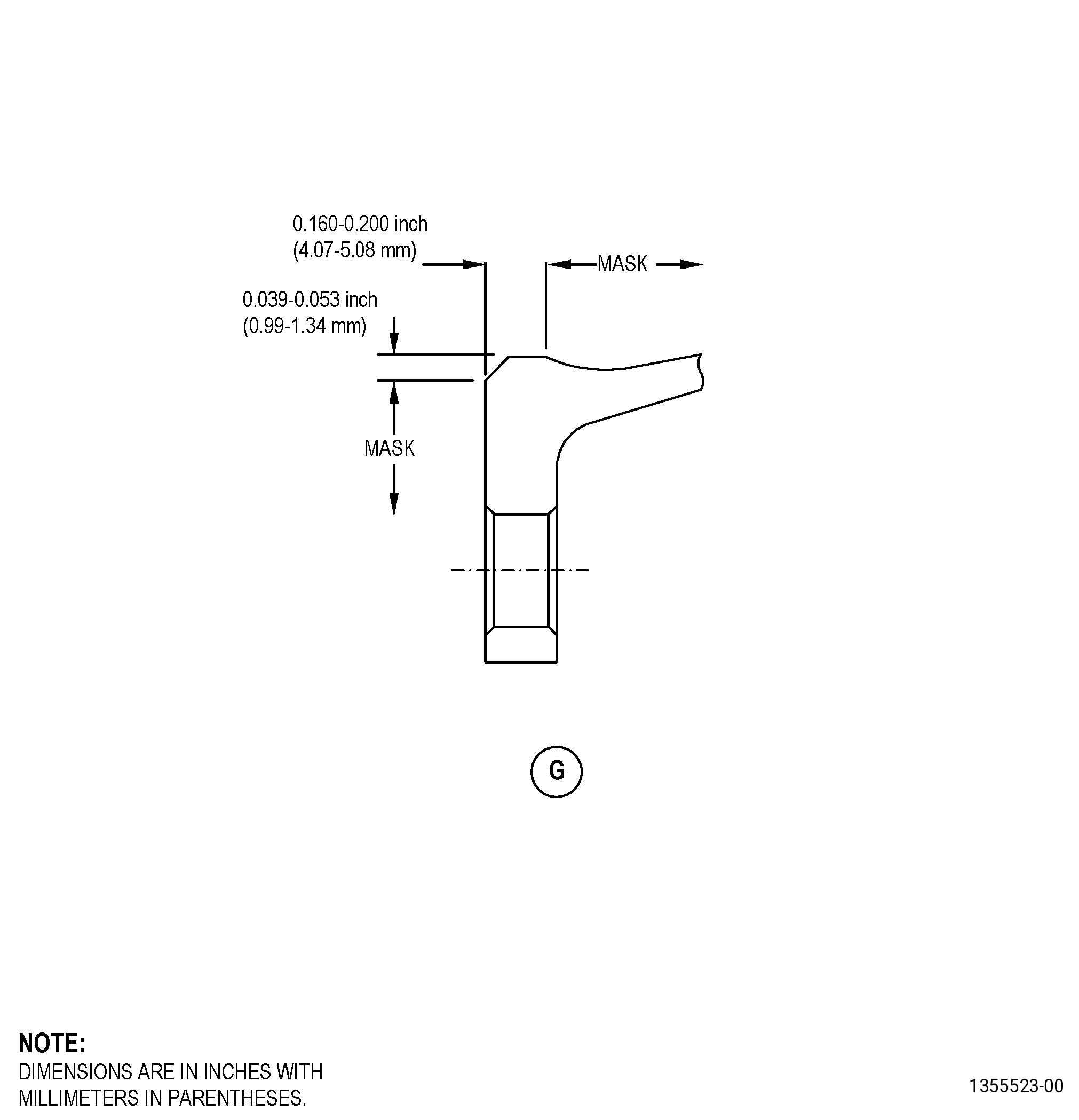
| A. | Refer to Figure 901 for specified dimensions and locations. |
| NOTE: |
|
| 4 . | Setup Information. |
| Subtask 72-31-45-350-007 |
| A. | Set up the spool for machining/shotpeening/thermal spraying as follows: |
| (1) | Install the spool in the holding fixture. |
| (2) | Surface A must be flat to 0.001 inch (0.02 mm) or less. |
| (3) | Diameter B must have a runout of 0.001 inch (0.02 mm) or less. |
| 5 . | Procedure. |
| Subtask 72-31-45-100-001 |
| A. | If necessary, clean the spool. Refer to TASK 72-31-45-100-801 (72-31-45, CLEANING 001). |
| Subtask 72-31-45-320-001 |
| B. | Machine the spool. Refer to TASK 70-00-03-800-004 (MACHINING DATA), Subtask 72-31-45-220-102 (paragraph 3.A.), Dimensional Information, Figure 901, and as follows: |
| (1) | Set up the spool for machining. Refer to Subtask 72-31-45-350-007 (paragraph 4.A.), Setup Information. |
| (2) | Machine diameter M to the in-process dimensions. |
| (3) | If there is HVOF thermal spray or plasma thermal spray on this diameter, remove all thermal spray from the repair diameter. |
| NOTE: |
|
| Subtask 72-31-45-350-008 |
| (4) | If necessary, blend the spool. Refer to TASK 70-42-00-350-002 (BLENDING AND REMOVAL OF HIGH METAL PROCEDURES) and as follows: |
| (a) | Remove burrs and rolled edges. |
| (b) | Break edges to 0.010 inch (0.25 mm) maximum. |
| Subtask 72-31-45-100-002 |
| C. | Clean the spool. Refer to TASK 70-21-00-110-051 (CHEMICAL CLEANING) and TASK 70-21-03-160-001 (CLEANING METHOD NO. 3 - STEAM CLEANING). |
| Subtask 72-31-45-110-006 |
| D. | Etch diameter M. Refer to TASK 70-24-00-110-033 (ETCHING PROCEDURES FOR FLUORESCENT-PENETRANT INSPECTION), TASK 70-24-01-110-034 (SWAB ETCHING PROCEDURE), and as follows: |
| (1) | Use Class C etchant. |
| Subtask 72-31-45-200-001 |
| E. | Do an inspection of diameter M. Refer to TASK 70-32-00-200-002 (INDIRECT INSPECTION METHODS), TASK 70-32-03-230-002 (SPOT-FLUORESCENT-PENETRANT INSPECTION), and as follows: |
| (1) | Use Class G penetrant. |
| (2) | Refer to TASK 72-31-45-200-807 (72-31-45, INSPECTION 001) for the fluorescent penetrant inspection limits. |
| Subtask 72-31-45-380-001 |
| F. | Peen the spool repair area. Refer to TASK 70-47-01-380-016 (SHOTPEENING) and do as follows: |
| (1) | Set up the spool for shotpeening. Refer to Subtask 72-31-45-350-007 (paragraph 4.A.), Setup Information, except as follows: |
| (a) | Surface A and diameter B may have a runout of up to 0.050 inch (1.27 mm). |
| (2) | Apply C10-021 plastic tape to all areas that you will not peen. Refer to Figure 902. |
| (3) | Use C04-166 CCW14 steel shot. |
| (4) | Peen to an intensity of 6-12N. |
| (5) | Coverage must be a minimum of 125 percent. |
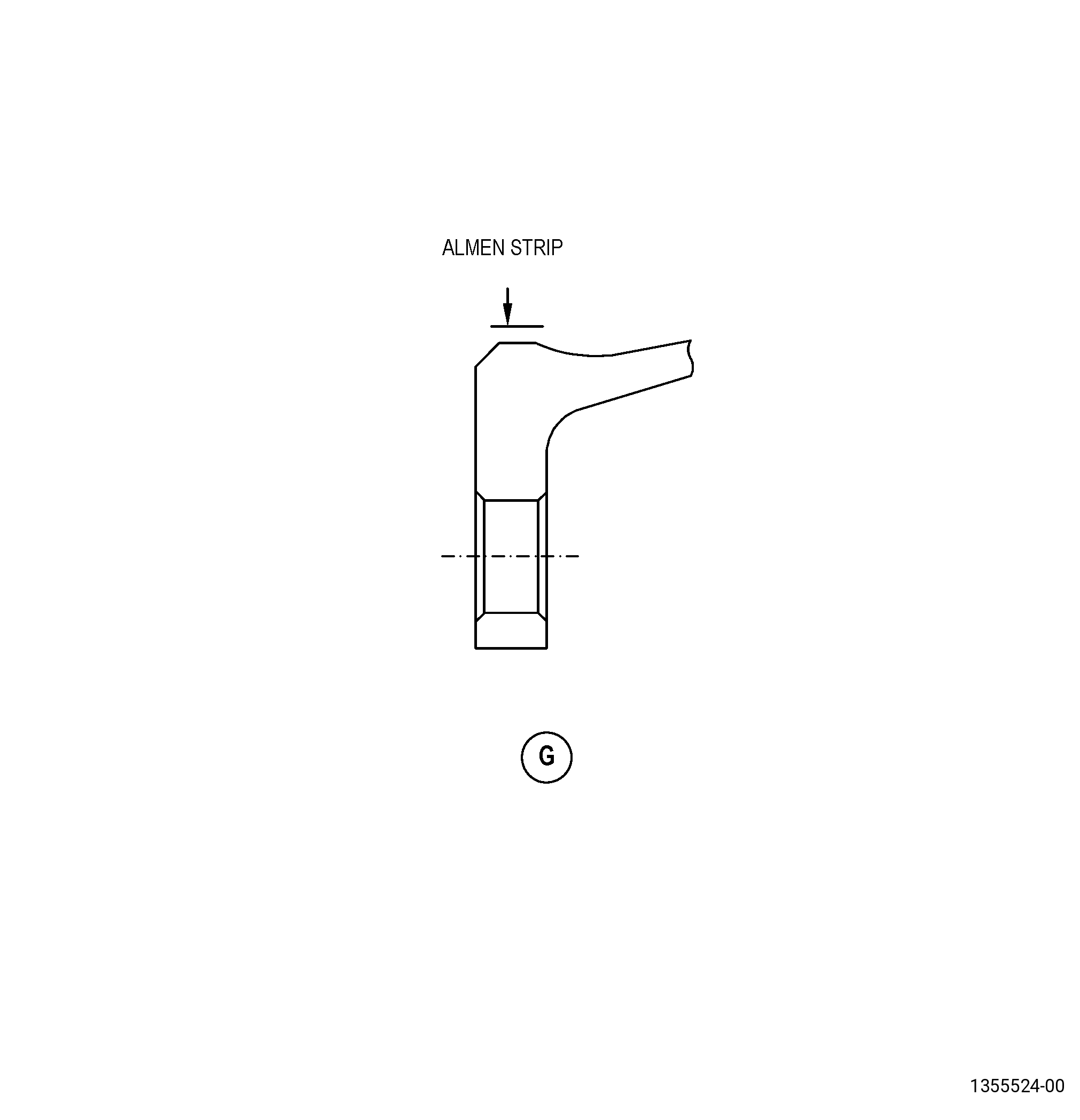
| (6) | Intensity verification is required in repaired area. Refer to Figure 903. |
| (7) | Remove the C10-021 plastic tape. |
| Subtask 72-31-45-340-002 |
| G. | Thermal-spray the spool and test specimens. Refer to TASK 70-49-00-340-001 (THERMAL SPRAYING), TASK 70-49-32-340-033 (THERMAL SPRAYING INCONEL 718 (POWDER)), Subtask 72-31-45-220-102 (paragraph 3.A.), Dimensional Information, Figure 901, and do as follows: |
| (1) | Apply C10-012 masking tape to all areas that will not be thermal sprayed. Refer to Figure 902. |
| (2) | Set up the spool for grit blasting and thermal spraying. Refer to Subtask 72-31-45-350-007 (paragraph 4.A.), Setup Information, except as follows: |
| (a) | Surface A and diameter B may have a runout of up to 0.050 inch (1.27 mm). |
| (3) | Perform the preliminary operations specified in TASK 70-49-00-340-001 (THERMAL SPRAYING). |
| (a) | Use the surface roughness limits for the nickel base material. |
| (4) | Apply C07-038 Inconel 718 powder to diameter M and the test specimens. Apply thermal spray coating to the test specimens and to diameter M at the same time and to the same thickness, and do as follows: |
| (a) | Overspray is not permitted. |
| (b) | Apply a sufficient quantity of thermal spray coating to machine to the finished dimension. |
| (c) | The final thermal spray thickness must be 0.006-0.011 inch (0.16-0.27 mm). |
| (d) | The thermal spray coating applied to the test specimens must simulate the part geometry, the spray angle, and the as-sprayed deposit thickness on the spool. |
| (5) | Do all the quality assurance testing specified in TASK 70-49-32-340-033 (THERMAL SPRAYING INCONEL 718 (POWDER)). |
| (6) | Remove the masking tape. |
| Subtask 72-31-45-220-100 |
| H. | Do a dimensional inspection of diameter M. Refer to Subtask 72-31-45-220-102 (paragraph 3.A.), Dimensional Information, Figure 901, and as follows: |
| (1) | If the thermal spray coating thickness is less than the requirement, and/or diameter M is less than the minimum finished dimension, remove and re-apply thermal spray coating. Refer to Subtask 72-31-45-320-001 (paragraph 5.B.). |
| Subtask 72-31-45-320-002 |
| I. | Machine the spool. Refer to TASK 70-00-03-800-004 (MACHINING DATA), Subtask 72-31-45-220-102 (paragraph 3.A.), Dimensional Information, Figure 901, and as follows: |
| (1) | Set up the spool for machining. Refer to Subtask 72-31-45-350-007 (paragraph 4.A.), Setup Information. |
| (2) | Machine diameter M to the finish dimensions. |
| (3) | The surface finish of diameter M must be 90 microinches (2.3 micrometers) or less. |
| Subtask 72-31-45-100-003 |
| J. | Clean the spool. Refer to TASK 70-21-00-110-051 (CHEMICAL CLEANING) and TASK 70-21-03-160-001 (CLEANING METHOD NO.3 - STEAM CLEANING). |
| Subtask 72-31-45-220-101 |
| K. | Do a visual inspection of the thermal spray as follows: |
| (1) | Spalling, chipping, cracking, or separation of the thermal spray coating is not permitted. |