| GENX-1B CLEANING,INSPECTION,AND REPAIR MANUAL | Dated: 12/09/2019 | |
| CIR 72-51-01 , REPAIR 009 | ||
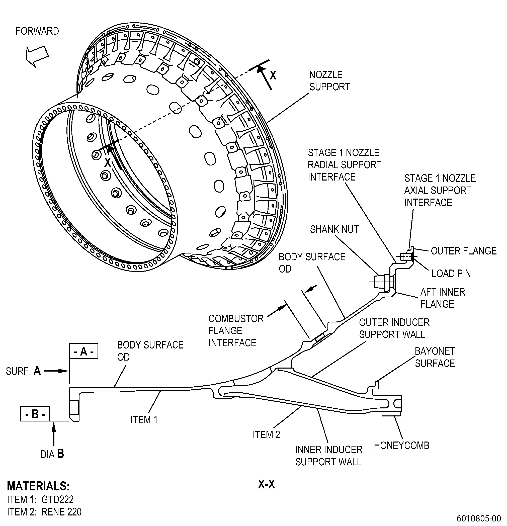
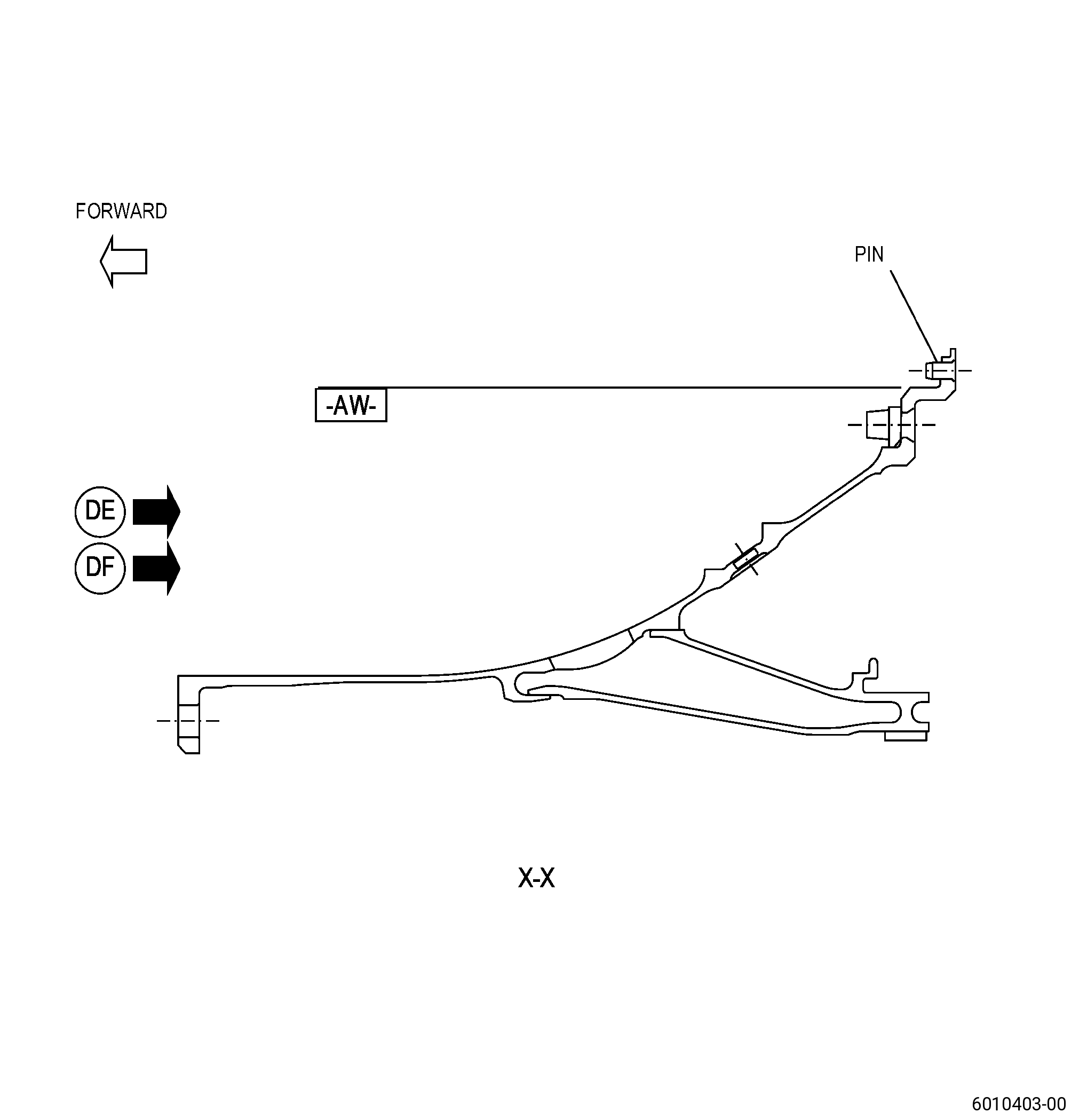
| HIGH PRESSURE TURBINE STAGE 1 NOZZLE SUPPORT - REPAIR - LOAD PIN REPLACEMENT | ||
| GENX-1B CLEANING,INSPECTION,AND REPAIR MANUAL | Dated: 12/09/2019 | |
| CIR 72-51-01 , REPAIR 009 | ||
| HIGH PRESSURE TURBINE STAGE 1 NOZZLE SUPPORT - REPAIR - LOAD PIN REPLACEMENT | ||
| * * * FOR ALL |
| TASK 72-51-01-300-809 |
| 1 . | Load Pin Replacement. |
| A. | This procedure gives instructions to repair the forward inner nozzle support (nozzle support) by removing and replacing load pins (pins) in the outer flange. Refer to Figure 901 and Figure 902. |
| B. | The following maximum repairable limits apply to this repair: |
| NOTE: |
|
| (4) | Visual Inspection. |
| (c) | Do an inspection of the outer flange area for: |
| 9 | Loose, damaged or missing load pin: |
| Maximum serviceable limit: |
|
| Maximum repairable limit: |
|
| C. | The subsequent table gives a list of the part numbers that are applicable to this procedure. All part numbers are applicable to all paragraphs unless specified differently. |
|
|||||||||||||||||||||||
| D. | Proprietary/Complex Process Statement. |
| (1) | None. |
| 2 . | Tools, Equipment, and Materials. |
| NOTE: |
|
| A. | Tools and Equipment. |
| (1) | Special Tools. None. |
| (2) | Standard Tools and Equipment. None. |
| (3) | Locally Manufactured Tools. None. |
| B. | Consumable Materials. None. |
| C. | Referenced Procedures. |
| D. | Expendable Parts. None. |
| E. | SPD Information. |
| (1) | Spare Supplied. |
|
| (2) | Protected Spares. None. |
| (3) | Locally Manufactured Spares. |
|
| F. | Special Solutions. None. |
| G. | Test Specimens. None. |
| 3 . | Dimensional Information. |
| Subtask 72-51-01-220-105 |
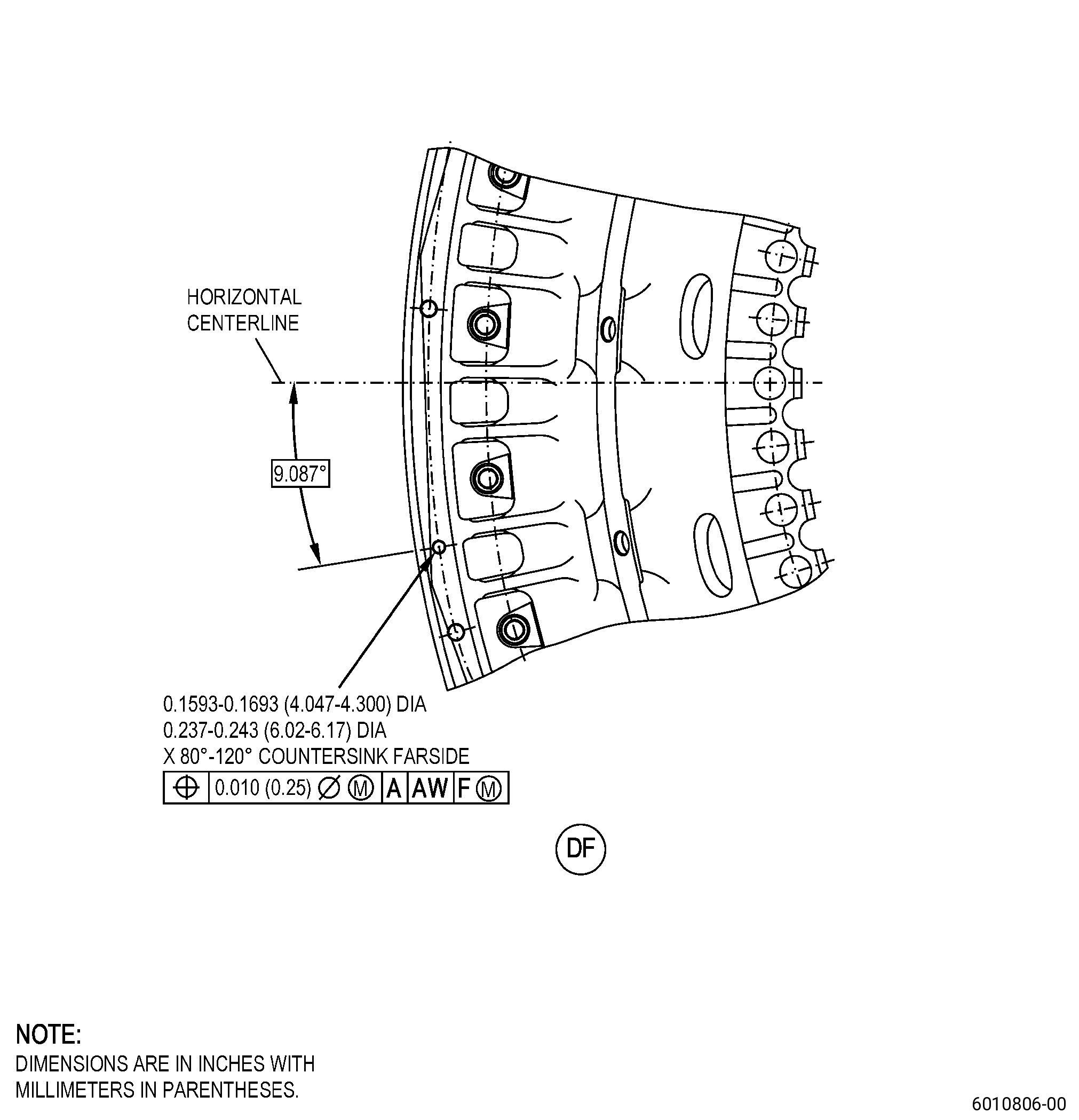
| A. | Refer to Figure 901, Figure 902, and Figure 903 for specified dimensions and locations. |
| NOTE: |
|
| NOTE: |
|
| 4 . | Setup Information. |
| None. |
| 5 . | Procedure. |
| Subtask 72-51-01-160-022 |
| A. | If necessary, clean the nozzle support. Refer to TASK 72-51-01-100-801 (72-51-01, CLEANING 001). |
| Subtask 72-51-01-320-015 |
| B. | Remove damaged pins from the 21 pins in the nozzle support outer flange. Refer to TASK 70-00-03-800-004 (MACHINING DATA), Figure 901, and Figure 902. |
| NOTE: |
|
| Subtask 72-51-01-230-030 |
| C. | Do an inspection of the nozzle support pin holes. Refer to TASK 70-32-00-200-002 (INDIRECT INSPECTION METHODS), TASK 70-32-03-230-002 (SPOT-FLUORESCENT-PENETRANT INSPECTION), and as follows: |
| (1) | Use Class A penetrant. |
| (2) | Indications 0.030 inch (0.76 mm) or less are not interpretable and are permitted. |
| (3) | Non-linear indications 0.060 inch (1.52 mm) or less with a minimum distance of 0.15 inch (3.9 mm) between indications are permitted. |
| (4) | Linear indications more than 0.030 inch (0.76 mm) are not permitted. |
| NOTE: |
|
| (5) | Through indications are not permitted. |
| (6) | Microshrinkage must agree with GEAE Photo Standard 8311253, Class 30. |
| Subtask 72-51-01-350-103 |
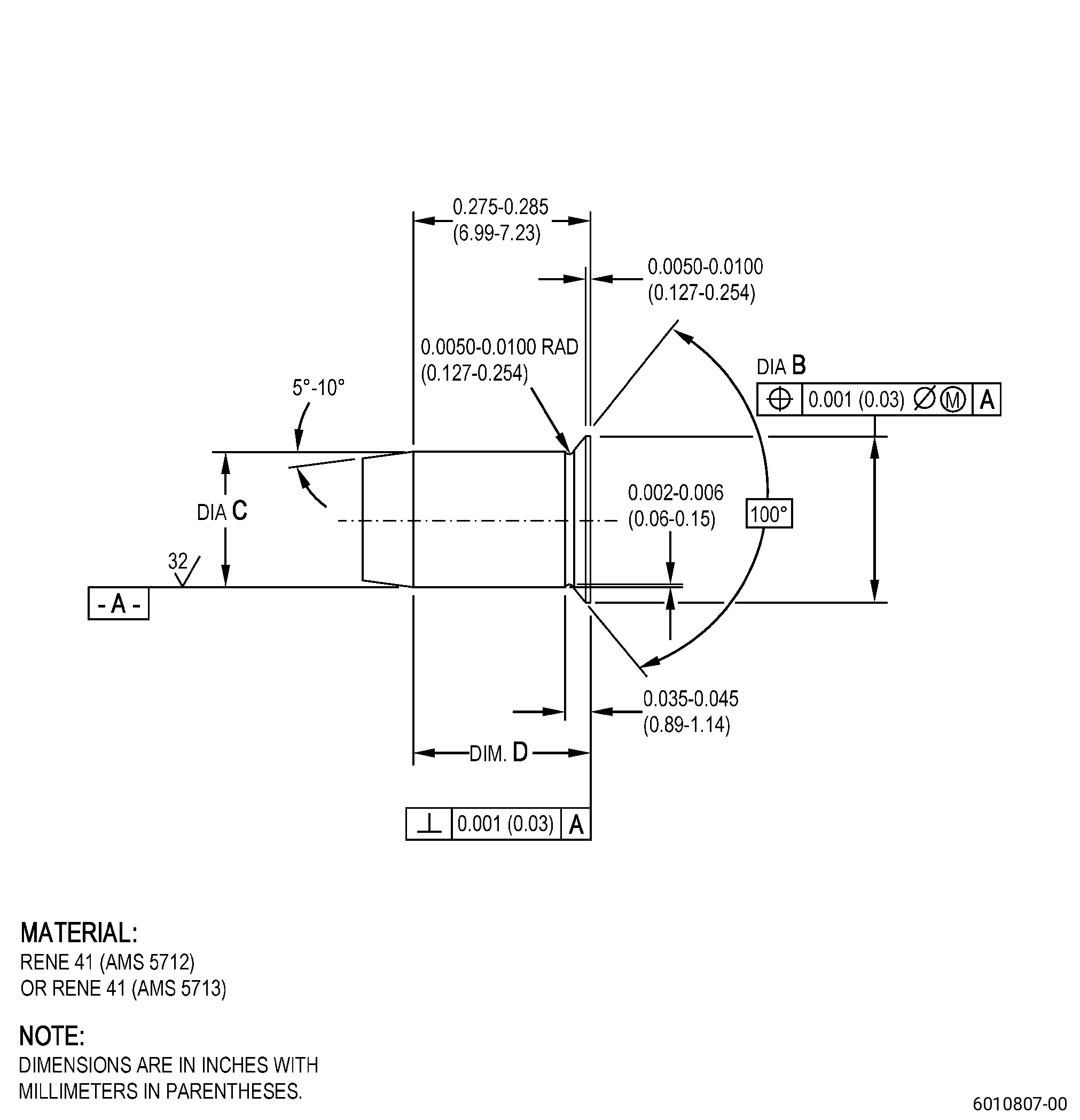
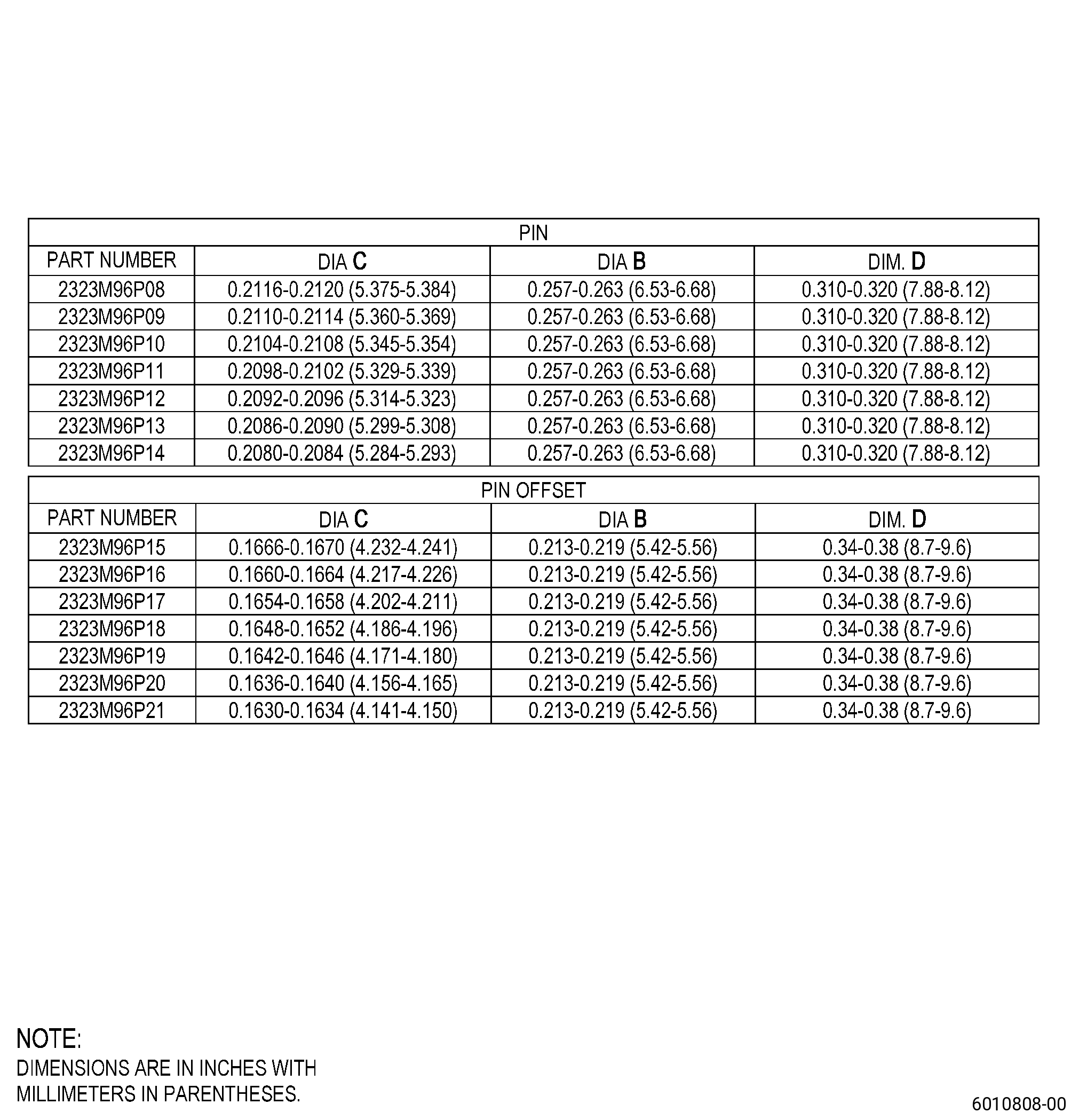
| D. | If necessary, make the pins. Refer to Figure 903 and as follows: |
| Subtask 72-51-01-370-047 |
| (1) | If the pins are made per AMS 5712, do a heat treatment of the pin to ensure mechanical properties. Refer to TASK 70-44-00-800-010 (HEAT TREATING), TASK 70-44-03-370-004 (FURNACE HEAT TREATMENT) , and as follows: |
| (a) | Do a solution heat treatment of the pins as follows: |
| 1 | Increase the temperature of the pin to a temperature of 1950°F (1066°C) and keep the temperature for 30 minutes. |
| 2 | Decrease the temperature of the pin to 800°F (427°C). |
| (b) | Do an age heat treatment of the pin as follows: |
| 1 | Increase the temperature of the pin to a temperature of 1400°F (760°C) and keep the temperature for 16 hours. |
| 2 | Decrease the temperature of the pin to 800°F (427°C). |
| Subtask 72-51-01-230-031 |
| (2) | Do an inspection of the pins. Refer to TASK 70-32-00-200-002 (INDIRECT INSPECTION METHODS), TASK 70-32-02-230-001 (FLUORESCENT PENETRANT INSPECTION), and as follows: |
| (a) | Use Class A penetrant. |
| (b) | Indications 0.030 inch (0.76 mm) or less are not interpretable and are permitted. |
| (c) | Non-linear indications 0.060 inch (1.52 mm) or less with a minimum distance of 0.50 inch (12.7 mm) between indications are permitted. |
| (d) | Linear indications more than 0.060 inch (1.52 mm) are not permitted. |
| NOTE: |
|
| Subtask 72-51-01-350-104 |
| E. | Install the pins in the nozzle support outer flange. Refer to Figure 901, Figure 902, and as follows: |
| Subtask 72-51-01-350-105 |
| (1) | Alternative Procedure Available. Install the new pins. Refer to TASK 72-51-01-300-809 (paragraph 2.E.). |
| (a) | Make sure the pin agrees with the necessary interference. |
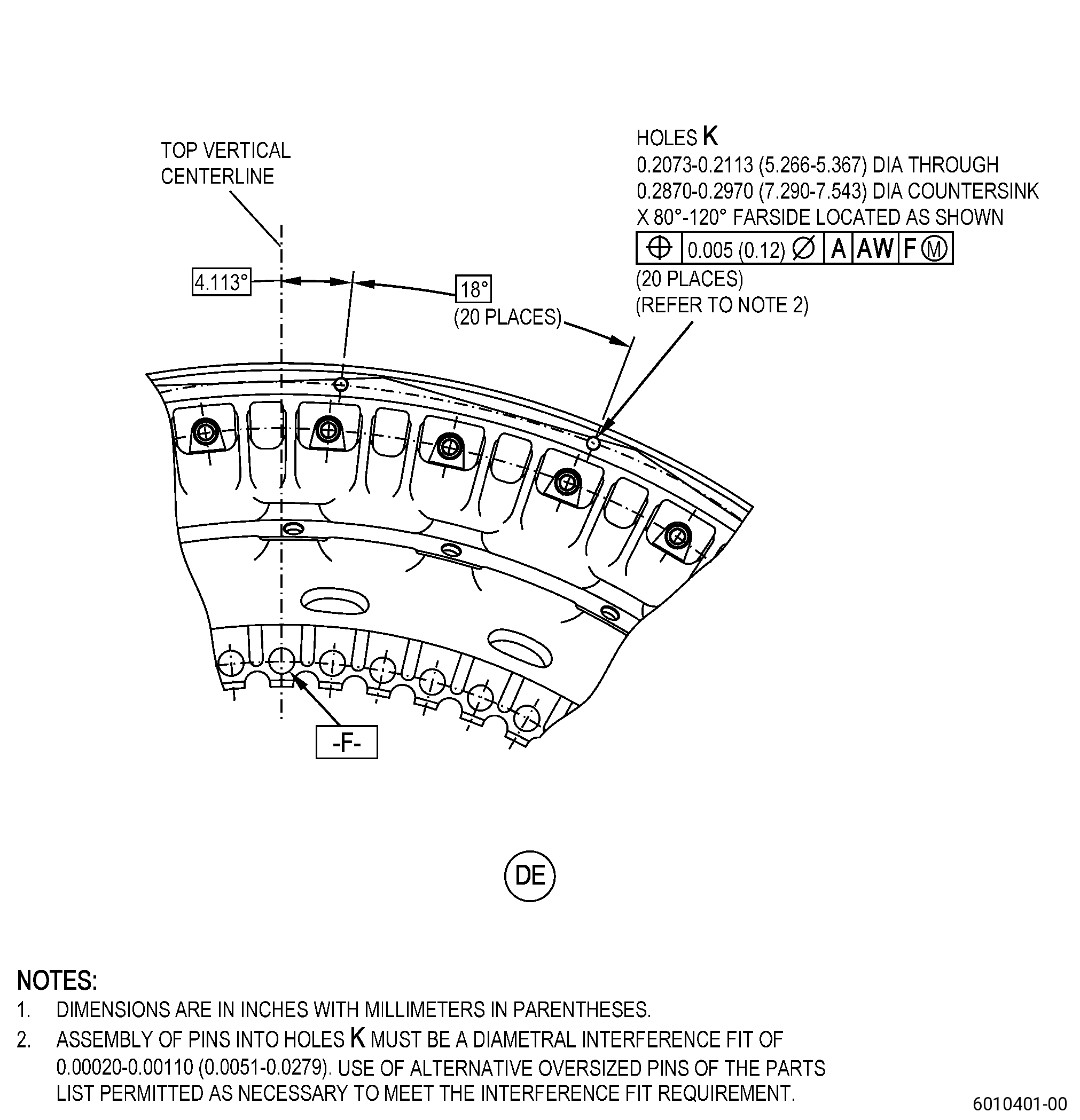
| (b) | You must assemble the pin into the hole with a diametrical interference fit of 0.0002-0.0011 inch (0.006-0.027 mm). |
| Subtask 72-51-01-350-106 |
| (1).A. | Alternative Procedure. Install the pins that you made. Refer to Figure 903 and as follows: |
| (a) | Make sure the pin agrees with the necessary interference. |
| (b) | You must assemble the pins into the holes with a diametrical interference fit of 0.0002-0.0011 inch (0.006-0.027 mm). |
| (2) | Chill the pin in dry ice to decrease the temperature of the pin for a minimum of 15 minutes. |
| (3) | Put the pin in the hole. |
| (4) | Lightly tap each pin with a plastic rod and mallet until is flush or below the surface of the nozzle support outer flange. |
| (5) | Let the pin get to the same temperature as the nozzle support. |
| (6) | Use a criss-cross method. |
| Subtask 72-51-01-220-106 |
| (7) | Do an inspection of the pins in the nozzle support outer flange. Refer to Figure 901, Figure 902, and as follows: |
| (a) | Make sure that the pins are flush or below surface of the nozzle support outer flange. |
| Subtask 72-51-01-220-107 |
| F. | Do an inspection of the nozzle support. Refer to TASK 72-51-01-200-801 (72-51-01, INSPECTION 001). |