| GENX-1B CLEANING,INSPECTION,AND REPAIR MANUAL | Dated: 11/15/2024 | |
| CIR 72-51-01 , INSPECTION 001 | ||
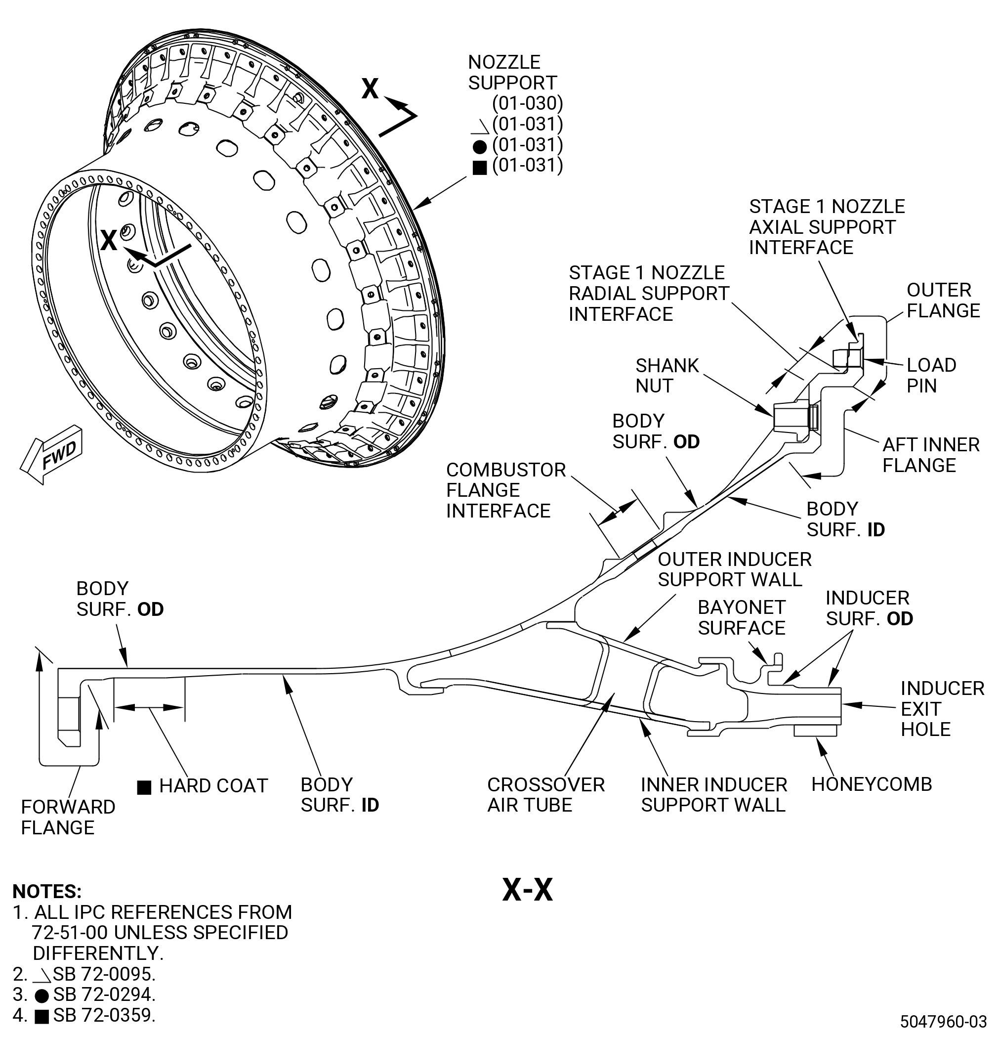
| HPT STAGE 1 NOZZLE SUPPORT - INSPECTION | ||
| GENX-1B CLEANING,INSPECTION,AND REPAIR MANUAL | Dated: 11/15/2024 | |
| CIR 72-51-01 , INSPECTION 001 | ||
| HPT STAGE 1 NOZZLE SUPPORT - INSPECTION | ||
| * * * FOR ALL |
| TASK 72-51-01-200-801 |
| 1 . | General. |
| A. | This procedure gives instructions to do an inspection of the HPT nozzle support (nozzle support). |
| • |
|
| • |
|
| • |
|
| • |
|
| • |
|
| • |
|
| • |
|
| 2 . | Tools, Equipment, and Materials. |
| NOTE: |
|
| A. | Tools and Equipment. |
| (1) | Special Tools. None. |
| (2) | Standard Tools and Equipment. None. |
| (3) | Locally Manufactured Tools. None. |
| B. | Consumable Materials. None. |
| C. | Referenced Procedures. |
| D. | Expendable Parts. None. |
| 3 . | Specific Inspection Procedure. |
| Subtask 72-51-01-350-030 |
| A. | If not removed during disassembly, remove and discard the old self-locking shank nut from the stage 1 nozzle assembly. Refer to 72-51-01-300-801 (72-51-01, REPAIR 001). |
| Subtask 72-51-01-230-001 |
| B. | Do an inspection of the nozzle support. Refer to TASK 70-32-00-200-002 (INDIRECT INSPECTION METHODS), TASK 70-32-02-230-001 (FLUORESCENT PENETRANT INSPECTION), Figure 803, Figure 803A, and as follows: |
| (1) | Use Class C penetrant. |
| (2) | Refer to TASK 70-31-02-220-003 (ACCEPTABILITY LIMITS FOR FLUORESCENT-PENETRANT INSPECTION) and as follows: |
| (a) | Use Class A limits. |
| (b) | Minimum spacing 0.150 inch (3.81 mm). |
| (3) | Microshrinkage severity limit must be class 30 maximum. Refer to the GEAE photo standard 8311253. |
| 4 . | Visual Inspection. |
| Subtask 72-51-01-220-104 |
| A. | Do a visual inspection of the nozzle support. Refer to Figure 801 and Figure 801A and as follows: |
| (1) | Unless otherwise specified, visual inspection limits for size and spacing must be the same as the FPI criteria. Refer to Subtask 72-51-01-230-001 (paragraph 3.B.). |
| NOTE: |
|
| Subtask 72-51-01-220-001 |
| B. | Do an inspection of all body surfaces for: |
| (1) | Cracks: |
| Maximum serviceable limit: |
|
| Repair method: |
|
| Subtask 72-51-01-220-002 |
| (2) | Dents: |
| Maximum serviceable limit: |
|
| Repair method: |
|
| Subtask 72-51-01-220-003 |
| (3) | Nicks and scratches: |
| Maximum serviceable limit: |
|
| Repair method: |
|
| Subtask 72-51-01-220-004 |
| (4) | Buckles: |
| Maximum serviceable limit: |
|
| Repair method: |
|
|
| Subtask 72-51-01-220-005 |
| C. | Do an inspection of the outer flange area for: |
| (1) | Cracks from the load pin hole: |
| Maximum serviceable limit: |
|
| Repair method: |
|
| Subtask 72-51-01-220-006 |
| (2) | Radial cracks from the outer diameter: |
| Maximum serviceable limit: |
|
| Repair method: |
|
| Subtask 72-51-01-220-007 |
| (3) | Dents: |
| Maximum serviceable limit: |
|
| Repair method: |
|
| Subtask 72-51-01-220-008 |
| (4) | Nicks, scratches, and gouges: |
| Maximum serviceable limit: |
|
| Maximum repairable limit: |
|
| Repair method: |
|
| Subtask 72-51-01-220-009 |
| (5) | Wear or fretting on the load pin diameter: |
| Maximum serviceable limit: |
|
| Repair method: |
|
| Subtask 72-51-01-220-010 |
| (6) | Wear or fretting on the stage 1 nozzle axial and radial support interface: |
| Maximum serviceable limit: |
|
| Repair method: |
|
| Subtask 72-51-01-220-011 |
| (7) | Wear on the outer flange aft face: |
| Maximum serviceable limit: |
|
| Maximum repairable limit: |
|
| Repair method: |
|
| Subtask 72-51-01-220-103 |
| (8) | Cracks on the stage 1 nozzle radial support interface: |
| Maximum serviceable limit: |
|
| Repair method: |
|
| Subtask 72-51-01-220-109 |
| (9) | Loose, damaged, or missing load pin: |
| Maximum serviceable limit: |
|
| Repair method: |
|
| Subtask 72-51-01-220-012 |
| D. | Do an inspection of the forward flange, combustor flange interface, and aft inner flange for: |
| (1) | Cracks from boltholes: |
| Maximum serviceable limit: |
|
| Repair method: |
|
| Subtask 72-51-01-220-013 |
| (2) | Dents: |
| Maximum serviceable limit: |
|
| Repair method: |
|
| Subtask 72-51-01-220-014 |
| (3) | Fretting in the bolthole: |
| Maximum serviceable limit: |
|
| Maximum repairable limit: |
|
| Repair method: |
|
| Subtask 72-51-01-220-015 |
| (4) | Pitting, corrosion, or fretting: |
| Maximum serviceable limit: |
|
| Repair method: |
|
| Subtask 72-51-01-220-045 |
| (5) | Deleted. |
| Subtask 72-51-01-220-059 |
| (6) | Deleted. |
| Subtask 72-51-01-220-027 |
| E. | Do an inspection of the braze joints (inner and outer inducer support wall) for: |
| (1) | Braze voids and cracks: |
| Maximum serviceable limit: |
|
| Repair method: |
|
| Subtask 72-51-01-220-028 |
| F. | Do an inspection of the honeycomb for: |
| (1) | Annular wear groove: |
| Maximum serviceable limit: |
|
| Repair method: |
|
| Subtask 72-51-01-220-029 |
| (2) | Cell damage/erosion: |
| Maximum serviceable limit: |
|
| Repair method: |
|
| Subtask 72-51-01-220-030 |
| (3) | Missing cells/visible inducer parent material: |
| Maximum serviceable limit: |
|
| Repair method: |
|
| Subtask 72-51-01-220-031 |
| G. | Do an inspection of the bayonet surfaces for: |
| (1) | Wear: |
| Maximum serviceable limit: |
|
| Repair method: |
|
| Subtask 72-51-01-220-032 |
| (2) | Nicks, dents, scratches, or other damage: |
| Maximum serviceable limit: |
|
| Repair method: |
|
| Subtask 72-51-01-220-061 |
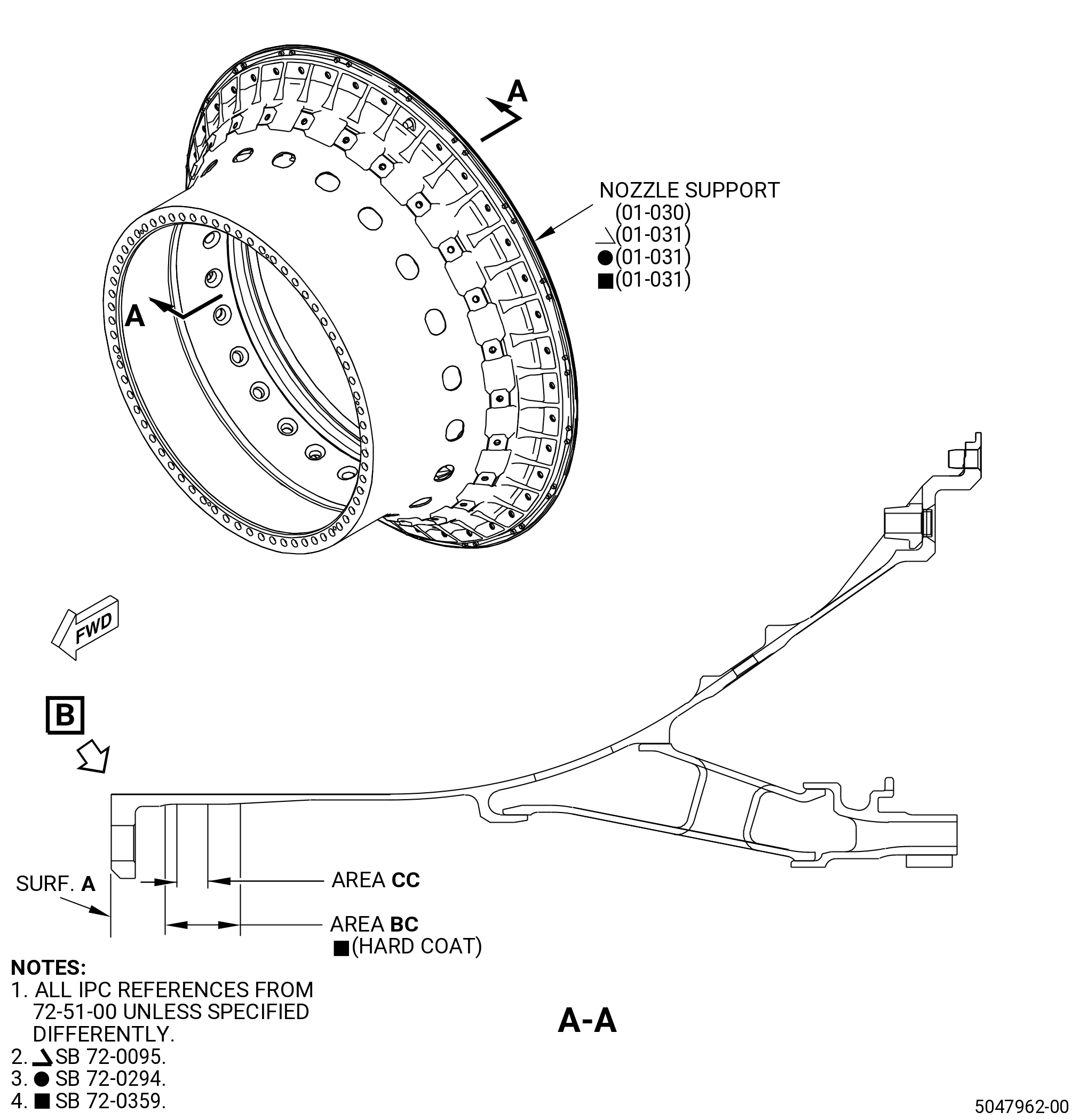
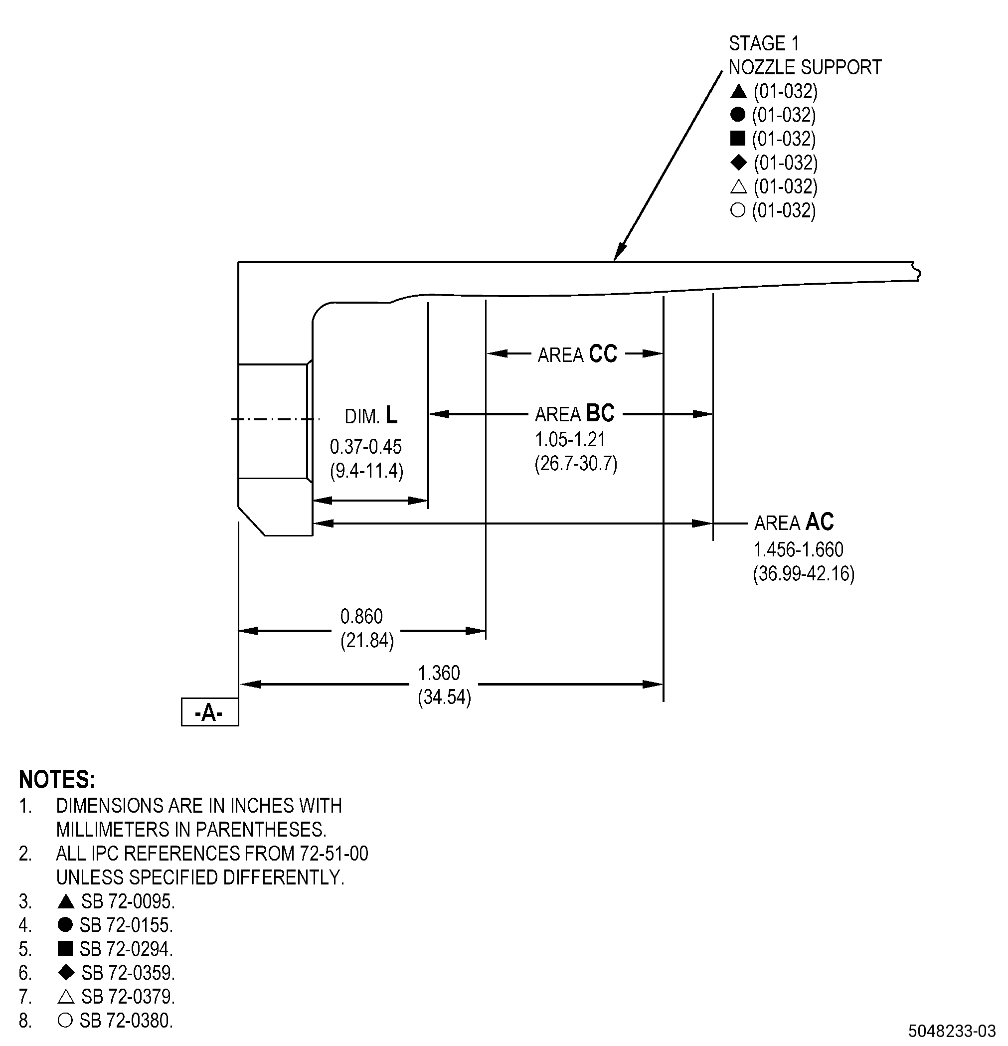
| H. | Do an inspection of the inner diameter of the forward flange area. Refer to Figure 802 and as follows: |
| * * * PRE SB 72-0359 |
| (1) | Erosion in area CC: |
| Maximum serviceable limit: |
|
| Maximum repairable limit 1: |
|
| Repair method 1: |
|
| Maximum repairable limit 2: |
|
| Repair method 2: |
|
| Maximum repairable limit 3: |
|
| Repair method 3: |
|
| * * * END PRE SB 72-0359 |
| Subtask 72-51-01-220-085 |
| * * * SB 72-0359 |
| (1).A. | Erosion in area CC: |
| Maximum serviceable limit: |
|
| Maximum repairable limit: |
|
| Repair method: |
|
| * * * END SB 72-0359( ) |
| Subtask 72-51-01-220-075 |
| (2) | Deleted. |
| Subtask 72-51-01-220-076 |
| * * * SB 72-0359 |
| (3) | Missing, eroded or damage hard coat in area BC: |
| Maximum serviceable limit: |
|
| Maximum repairable limit: |
|
| Repair method: |
|
| * * * END SB 72-0359 |
| Subtask 72-51-01-220-095 |
| * * * PRE SB 72-0359 |
| (4) | Erosion in area AC (only between forward flange and area CC): |
| Maximum serviceable limit: |
|
| Maximum repairable limit 1: |
|
| Repair method 1: |
|
| Maximum repairable limit 2: |
|
| Repair method 2: |
|
| * * * END PRE SB 72-0359 |
| Subtask 72-51-01-220-110 |
| * * * SB 72-0359 |
| (4).A. | Erosion in area AC (only between forward flange and area BC): |
| Maximum serviceable limit: |
|
| Maximum repairable limit 1: |
|
| Repair method 1: |
|
| Maximum repairable limit 2: |
|
| Repair method: |
|
| * * * END SB 72-0359 |
| Subtask 72-51-01-220-120 |
| I. | Do an inspection of the inducer surfaces for: |
| (1) | Cracks: |
| Maximum serviceable limit: |
|
| Repair method: |
|
| Subtask 72-51-01-220-128 |
| * * * PRE SB 72-0155 |
| (2) | Scratches on the inducer surface outer diameter (OD): |
| Maximum serviceable limit: |
|
| Maximum repairable limit: |
|
| Repair method: |
|
| * * * END PRE SB 72-0155 |
| Subtask 72-51-01-220-129 |
| * * * SB 72-0155( PIP2 FINS (M46) New Material ) |
| (3) | Scratches on the inducer surfaces outer diameter (OD), excluding fillet radius to radial surface, chamfer area and bypass holes (understand as area of 0.050 inch (1.27 mm) around the bypass holes edges): |
| Maximum serviceable limit: |
|
| Maximum repairable limit: |
|
| Repair method: |
|
| * * * END SB 72-0155( PIP2 FINS (M46) New Material ) |
| Subtask 72-51-01-220-131 |
| (4) | Wear or erosion on the inducer exit hole: |
| Maximum serviceable limit: |
|
| Maximum repairable limit: |
|
| Repair method: |
|
|
|
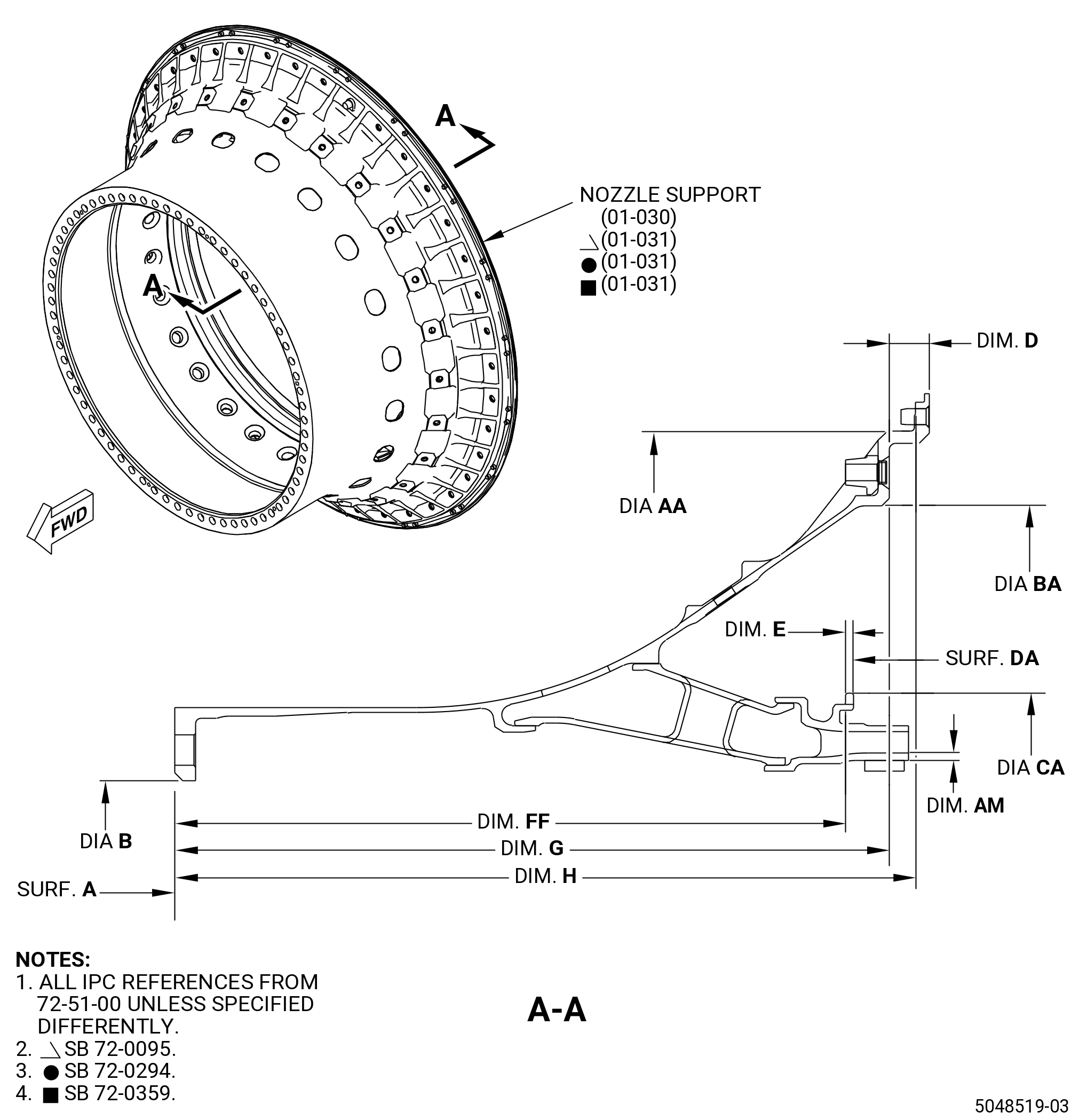
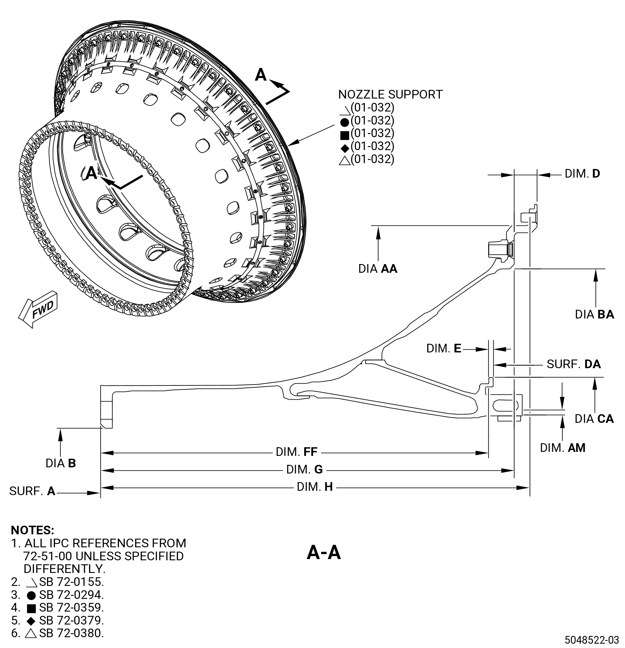
| 5 . | Dimensional Inspection. |
| Refer to Figure 803 and Figure 803A. |
| Subtask 72-51-01-220-034 |
| A. | With surface A restrained within 0.002 inch (0.05 mm) and diameter B restrained within tolerance all dimensions must be met. |
| B. | Measure the diameter at six equally spaced locations to find the average diameter. |
| C. | Measure the dimension at eight equally spaced locations to find the average dimension. |
| D. | Record the average diameter and average dimension. Include the clock positions where they were measured. |
| Subtask 72-51-01-220-035 |
| E. | Do an inspection of the nozzle support for: |
| (1) | Diameter AA: |
| Minimum serviceable limit: |
|
| Maximum serviceable limit: |
|
| Repair method: |
|
| Subtask 72-51-01-220-122 |
| (2) | Runout at diameter AA: |
| Maximum serviceable limit: |
|
| Repair method: |
|
| Subtask 72-51-01-220-036 |
| (3) | Diameter BA: |
| Minimum serviceable limit: |
|
| Maximum serviceable limit: |
|
| Repair method: |
|
| Subtask 72-51-01-220-123 |
| (4) | Runout at diameter BA: |
| Maximum serviceable limit: |
|
| Repair method: |
|
| Subtask 72-51-01-220-037 |
| (5) | Diameter CA: |
| Minimum serviceable limit: |
|
| Maximum serviceable limit: |
|
| Repair method: |
|
| Subtask 72-51-01-220-038 |
| (6) | Runout of surface DA (surface A restrained flat within 0.002 inch (0.05 mm)): |
| Maximum serviceable limit: |
|
| Repair method: |
|
| Subtask 72-51-01-220-039 |
| (7) | Dimension E (if wear observed, measure in worn area): |
| Minimum serviceable limit: |
|
| Maximum serviceable limit: |
|
| Repair method: |
|
| Subtask 72-51-01-220-040 |
| (8) | Dimension FF (it can be measured directly from surface A to the tab mating surface (fwd face), or indirectly with the max length from FINS forward flange to back side of the bayonet tab minus the tab thickness (dimension E)): |
| Minimum serviceable limit: |
|
| Maximum serviceable limit: |
|
| Repair method: |
|
| Subtask 72-51-01-220-041 |
| (9) | Dimension H: |
| Minimum serviceable limit: |
|
| Maximum serviceable limit: |
|
| Repair method: |
|
| Subtask 72-51-01-220-060 |
| (10) | Diameter B: |
| Minimum serviceable limit: |
|
| Maximum serviceable limit: |
|
| Repair method: |
|
| Subtask 72-51-01-220-124 |
| (11) | Measure dimension G: |
| Minimum serviceable limit: |
|
| Maximum serviceable limit: |
|
| Repair method: |
|
| Subtask 72-51-01-220-125 |
| (12) | Measure dimension D: |
| Minimum serviceable limit: |
|
| Maximum serviceable limit: |
|
| Repair method: |
|
| Subtask 72-51-01-220-077 |
| F. | Alternative dimensional inspection criteria for bayonets. Measure dimension FF (in worn area) and dimension G for each affected bayonet tab that is outside standard inspection limits, refer to Subtask 72-51-01-220-039 (paragraph 5.E.(5)) and/or Subtask 72-51-01-220-040 (paragraph 5.E.(6)). Take measurement at corresponding circumferential location as affected tab. The Subtask 72-51-01-220-034 (paragraph 5.C.) in Dimensional Inspection (average dimension) is not valid for special inspection described by this paragraph. If dimension E and/or dimension FF are outside the serviceable limits, do as follows: |
| (1) | Deleted. |
| Subtask 72-51-01-220-078 |
| (2) | Calculate dimension J, refer to Figure 803 for dimension definition, and as follows: |
| (a) | Dimension J = Dimension G - Dimension FF. |
| (b) | If dimension J is more than 0.560 inch (14.22 mm), dimension E and dimension FF are outside the serviceable limits, is acceptable. |
| Subtask 72-51-01-350-031 |
| G. | Install new self-locking shank nuts in the stage 1 nozzle assembly. Refer to TASK 72-51-01-300-801 (72-51-01, REPAIR 001). |