![]() | GENX-1B CLEANING,INSPECTION,AND REPAIR MANUAL | Dated: 11/18/2020 |
CIR 72-51-01 , REPAIR 012 | ||
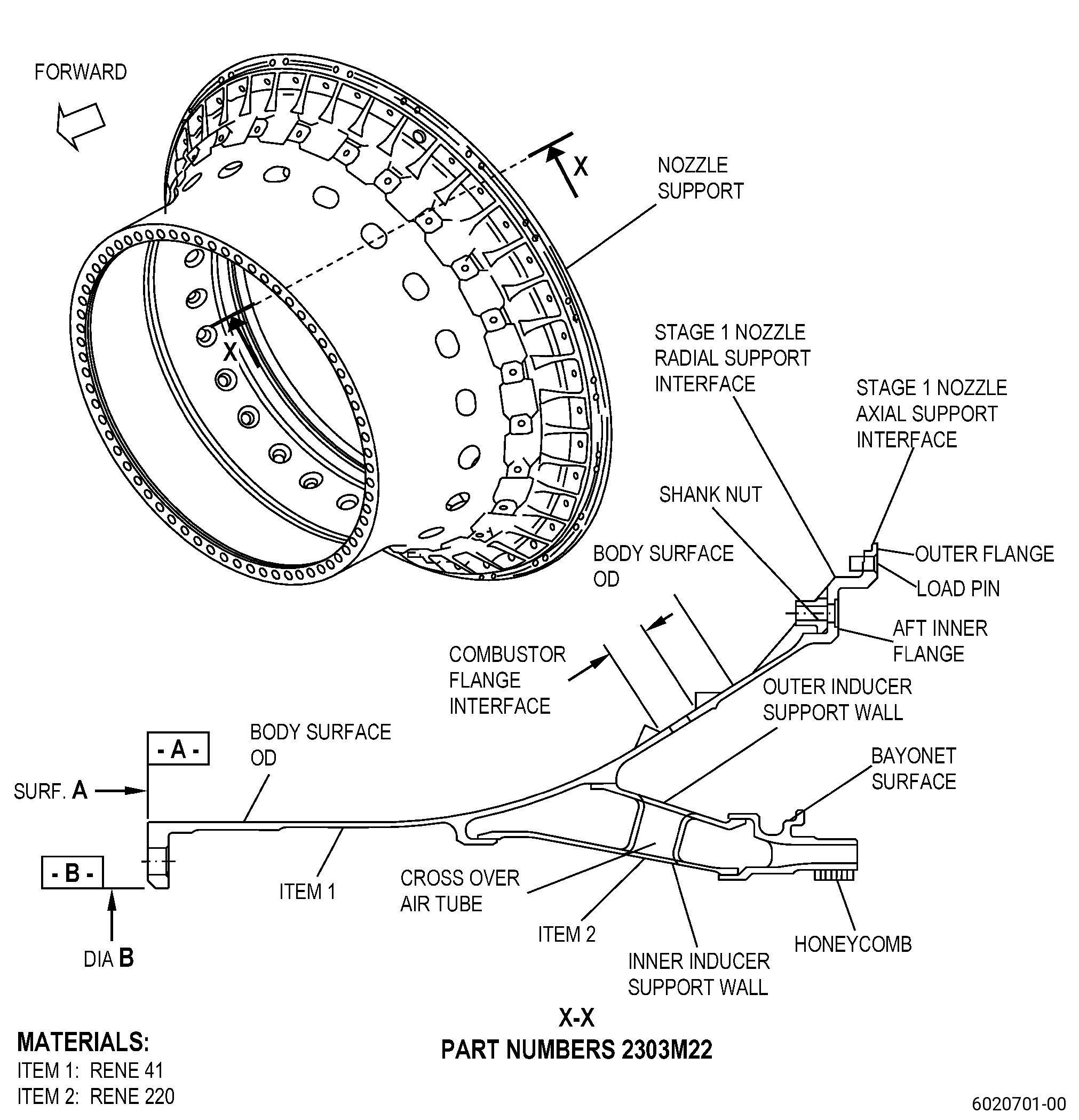
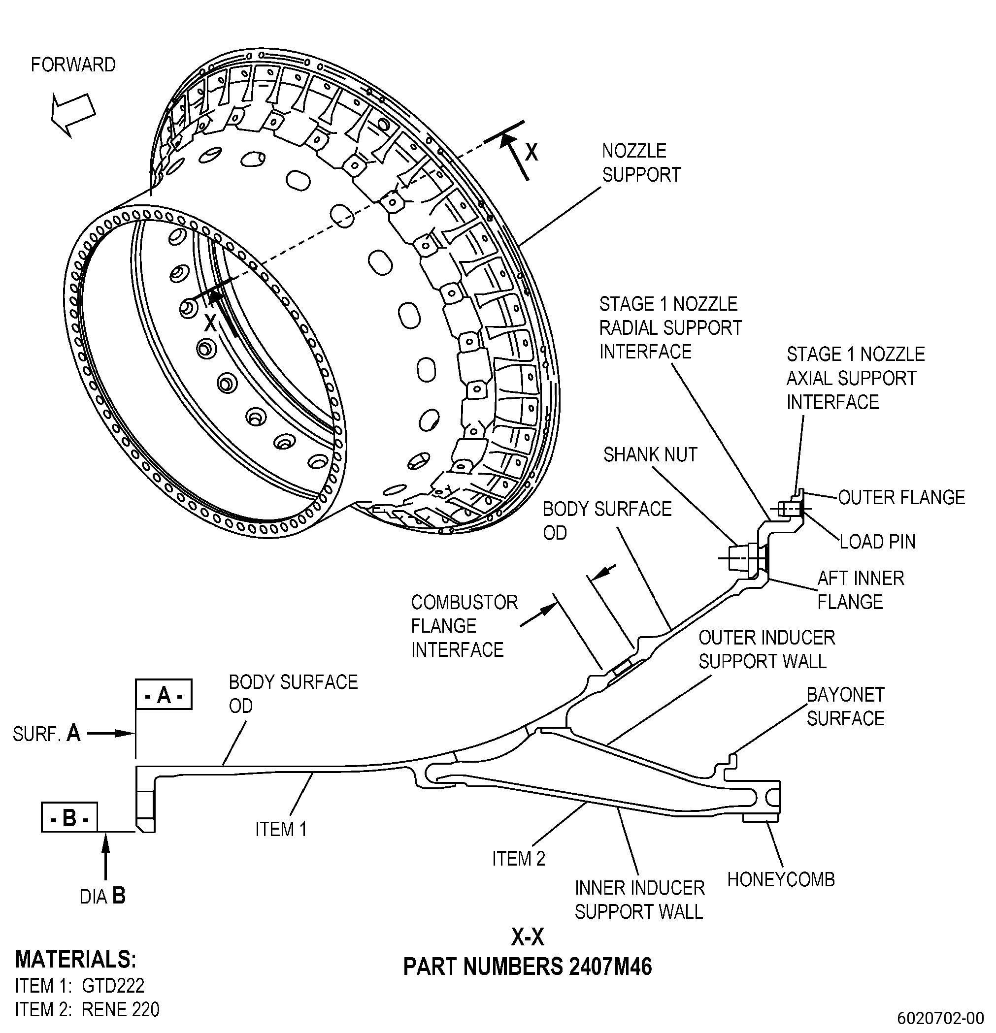
HIGH PRESSURE TURBINE STAGE 1 NOZZLE SUPPORT - REPAIR - WELD LINEAR INDICATION REPAIR OF THE INDUCER OUTER SUPPORT WALL, INNER SUPPORT WALL, AND CROSS OVER TUBES | ||
* * * FOR ALL |
TASK 72-51-01-300-812 |
1 . | Weld Linear Indication Repair of the Inducer Outer Support Wall, Inner Support Wall, and Cross Over Tubes. |
A. | This procedure gives instructions to repair the high pressure turbine stage 1 nozzle support (nozzle support) by welding the linear indications in the inducer (inducer) outer support wall, inner support wall, and cross over tubes. Refer to Figure 901. |
B. | The following maximum repairable limits apply to this repair: |
NOTE: |
|
(4) | Visual Inspection. |
(i) | Do an inspection of the inducer surfaces for: |
3 | Cracks: |
Maximum repairable limit: |
|
C. | The subsequent table gives a list of the part numbers that are applicable to this procedure. All part numbers are applicable to all paragraphs unless specified differently. |
|
D. | Proprietary/Complex Process Statement. |
(1) | None. |
2 . | Tools, Equipment, and Materials. |
NOTE: |
|
A. | Tools and Equipment. |
(1) | Special Tools. None. |
(2) | Standard Tools and Equipment. None. |
(3) | Locally Manufactured Tools. None. |
B. | Consumable Materials. |
|
C. | Referenced Procedures. |
D. | Expendable Parts. None. |
E. | SPD Information. |
(1) | Spare Supplied. None. |
(2) | Protected Spares. None. |
(3) | Locally Manufactured Spares. None. |
F. | Special Solutions. None. |
G. | Test Specimens. None. |
3 . | Dimensional Information. |
Subtask 72-51-01-220-115 |
A. | Refer to Figure 901 for specified dimensions and locations. |
NOTE: |
|
NOTE: |
|
4 . | Setup Information. |
Subtask 72-51-01-350-121 |
A. | Set-up the nozzle support for heat treatment as follows: |
(1) | Put Hastelloy X shims on top of a graphite plate as follows: |
(a) | Put the Hastelloy X shims on top of a graphite plate to make sure that the nozzle support will not touch the graphite plate directly during the heat treatment. |
CAUTION: |
|
(2) | Put the nozzle support on the Hastelloy X shims that are equally spaced on the top surface of the graphite plate. |
(3) | For the quantity and location requirements of the load thermocouples, refer to TASK 70-44-03-370-004 (FURNACE HEAT TREATMENT) . |
5 . | Procedure. |
Subtask 72-51-01-160-027 |
A. | If necessary, clean the nozzle support. Refer to TASK 72-51-01-100-801 (72-51-01, CLEANING 001). |
Subtask 72-51-01-350-122 |
B. | Remove the shank nuts from the nozzle support. Refer to TASK 72-51-01-300-801 (72-51-01, REPAIR 001). |
Subtask 72-51-01-350-123 |
C. | Blend the linear indication in the inducer to prepare it for welding process. Refer to TASK 70-42-00-350-002 (BLENDING AND REMOVAL OF HIGH METAL PROCEDURES) and Figure 901. |
NOTE: |
|
Subtask 72-51-01-160-028 |
CAUTION: |
|
D. | Clean the nozzle support. Refer to TASK 72-51-01-100-801 (72-51-01, CLEANING 001). |
Subtask 72-51-01-110-039 |
E. | Etch the inducer repair areas of the nozzle support. Refer to TASK 70-24-00-110-033 (ETCHING PROCEDURES FOR FLUORESCENT-PENETRANT INSPECTION), TASK 70-24-01-110-034 (SWAB ETCHING PROCEDURE), and as follows: |
(1) | Use Class C etchant. |
Subtask 72-51-01-230-033 |
F. | Do an inspection of the inducer repair area of the nozzle support. Refer to TASK 70-32-00-200-002 (INDIRECT INSPECTION METHODS), TASK 70-32-03-230-002 (SPOT-FLUORESCENT-PENETRANT INSPECTION). Refer to Figure 901, and as follows: |
(1) | Use Class A penetrant. |
(2) | linear indications of 0.030 inch (0.76 mm) or less are not interpretable and are permitted. |
NOTE: |
|
(3) | Non-linear indications of 0.060 inch (1.52 mm) or less with a minimum distance of 0.15 inch (3.9 mm) between indications are permitted. |
(4) | Linear indications of more than 0.030 inch (0.76 mm) are not permitted. |
NOTE: |
|
(5) | Through indications are not permitted. |
(6) | Microshrinkage must agree with GEAE Photo Standard 8311253, Class 30. |
Subtask 72-51-01-370-048 |
G. | Optional Procedure. Alternative Procedure Available. Heat-treat the nozzle support. Refer to TASK 70-44-00-800-010 (HEAT TREATING), TASK 70-44-03-370-004 (FURNACE HEAT TREATMENT) , and as follows: |
(1) | Set-up the nozzle support for heat treatment. Refer to Subtask 72-51-01-350-121 (paragraph 4.A.). |
(2) | Do a solution heat treatment of the nozzle support as follows: |
(a) | Use a vacuum of 1.0 micron of mercury or less. |
(b) | Increase the temperature of the nozzle support to a temperature range of 1835 to 1885°F (1002 to 1029°C) and keep the temperature for 20-30 minutes. |
(c) | Decrease the temperature of the nozzle support to 1000°F (538°C) in less than 30 minutes. |
(d) | Remove the nozzle support from the furnace. |
Subtask 72-51-01-370-049 |
G.A. | Optional Procedure. Alternative Procedure. Heat-treat the nozzle support. Refer to TASK 70-44-00-800-010 (HEAT TREATING), TASK 70-44-03-370-004 (FURNACE HEAT TREATMENT) , and as follows: |
(1) | Set-up the nozzle support for heat treatment. Refer to Subtask 72-51-01-350-121 (paragraph 4.A.). |
(2) | Do a solution heat treatment of the nozzle support as follows: |
(a) | Use a vacuum of 1.0 micron of mercury or less. |
(b) | Increase the temperature of the nozzle support to a range of 1700 to 1750ºF (927 to 954ºC) and as follows: |
1 | Keep this temperature for 10-15 minutes or until the vacuum rate gets back to a vacuum pressure of 5.0 X 10⁻⁴ mm Hg or less (6.7 x 10⁻⁴ millibar). |
CAUTION: |
|
(c) | Increase the temperature of the nozzle support to a temperature range of 1875 to 1925ºF (1024 to 1052ºC) at a rate of 20 to 25ºF (11 to 14ºC) for each minute and as follows: |
1 | Keep this temperature for a maximum of 3-5 minutes. |
2 | The accumulated time more than 1900ºF must be 30 minutes or less. |
(d) | Decrease the temperature of the nozzle support to a temperature range of 1750 to 1800ºF (954 to 982ºC) at a minimum rate of 20ºF (11ºC) for each minute and as follows: |
1 | Keep this temperature for 10-15 minutes. |
(e) | Decrease the temperature of the nozzle support to 975 to 1025ºF (524 to 552ºC) in 30 minutes or less. |
NOTE: |
|
(f) | Remove the nozzle support from the furnace. |
Subtask 72-51-01-310-014 |
H. | Weld the inducer prepared areas of the nozzle support. Refer to TASK 70-41-00-310-001 (WELDING AND BRAZING PRACTICES), Figure 901, and as follows: |
(1) | Use C06-039 Rene 220 weld wire. |
Subtask 72-51-01-350-124 |
WARNING: |
|
I. | Blend the inducer welded areas of the nozzle support to the initial contour. Refer to TASK 70-42-00-350-002 (BLENDING AND REMOVAL OF HIGH METAL PROCEDURES). |
Subtask 72-51-01-160-029 |
J. | Clean the nozzle support. Refer to TASK 72-51-01-100-801 (72-51-01, CLEANING 001). |
Subtask 72-51-01-230-034 |
K. | Optional Procedure. Alternative Procedure Available. Do an inspection of the inducer repair area of the nozzle support. Refer to TASK 70-32-00-200-002 (INDIRECT INSPECTION METHODS), TASK 70-32-03-230-002 (SPOT-FLUORESCENT-PENETRANT INSPECTION), and as follows: |
(1) | Use Class A penetrant. |
(2) | Linear indications of 0.030 inch (0.76 mm) or less are not interpretable and are permitted. |
NOTE: |
|
(3) | Non-linear indications 0.060 inch (1.52 mm) or less with a minimum distance of 0.15 inch (3.9 mm) between indications are permitted. |
(4) | Linear indications more than 0.030 inch (0.76 mm) are not permitted. |
NOTE: |
|
(5) | Through indications are not permitted. |
(6) | Microshrinkage must agree with GEAE Photo Standard 8311253, Class 30. |
Subtask 72-51-01-230-035 |
K.A. | Optional Procedure. Alternative Procedure. Do an inspection of the inducer repair area of the nozzle support. Refer to TASK 70-32-00-200-002 (INDIRECT INSPECTION METHODS), TASK 70-32-02-230-001 (FLUORESCENT PENETRANT INSPECTION), and as follows: |
(1) | Use Class A penetrant. |
(2) | Linear indications of 0.030 inch (0.76 mm) or less are not interpretable and are permitted. |
NOTE: |
|
(3) | Non-linear indications 0.060 inch (1.52 mm) or less with a minimum distance of 0.15 inch (3.9 mm) between indications are permitted. |
(4) | Linear indications more than 0.030 inch (0.76 mm) are not permitted. |
NOTE: |
|
(5) | Through indications are not permitted. |
(6) | Microshrinkage must agree with GEAE Photo Standard 8311253, Class 30. |
Subtask 72-51-01-160-030 |
L. | If necessary, clean the nozzle support. Refer to TASK 72-51-01-100-801 (72-51-01, CLEANING 001). |
Subtask 72-51-01-370-050 |
M. | Alternative Procedure Available. Heat-treat the nozzle support. Refer to TASK 70-44-00-800-010 (HEAT TREATING), TASK 70-44-03-370-004 (FURNACE HEAT TREATMENT), and as follows: |
(1) | Set-up the nozzle support for heat treatment. Refer to Subtask 72-51-01-350-121 (paragraph 4.A.). |
(2) | Do a solution heat treatment of the nozzle support as follows: |
(a) | Use a vacuum of 1.0 micron of mercury or less. |
(b) | Increase the temperature of the nozzle support to a temperature range of 1835 to 1885°F (1002 to 1029°C) and keep the temperature for 20-30 minutes. |
(c) | Decrease the temperature of the nozzle support to 1000°F (538°C) in less than 30 minutes. |
(d) | Remove the nozzle support from the furnace. |
Subtask 72-51-01-370-051 |
M.A. | Alternative Procedure. Heat-treat the nozzle support. Refer to TASK 70-44-00-800-010 (HEAT TREATING), TASK 70-44-03-370-004 (FURNACE HEAT TREATMENT) , and as follows: |
(1) | Set-up the nozzle support for heat treatment. Refer to Subtask 72-51-01-350-121 (paragraph 4.A.). |
(2) | Do a solution heat treatment of the nozzle support as follows: |
(a) | Use a vacuum of 1.0 micron of mercury or less. |
(b) | Increase the temperature of the nozzle support to a range of 1700 to 1750ºF (927 to 954ºC) and as follows: |
1 | Keep this temperature for 10-15 minutes or until the vacuum rate gets back to a vacuum pressure of 5.0 x 10⁻⁴ mm Hg or less (6.7 x 10⁻⁴ millibar). |
(c) | Increase the temperature of the nozzle support to a temperature range of 1875 to 1925ºF (1024 to 1052ºC) at a rate of 20 to 25ºF (11 to 14ºC) for each minute and as follows: |
1 | Keep this temperature for a maximum of 3-5 minutes. |
2 | The accumulated time more than 1900ºF must be 30 minutes or less. |
CAUTION: |
|
(d) | Decrease the temperature of the nozzle support to a temperature range of 1750 to 1800ºF (954 to 982ºC) at a minimum rate of 20ºF (11ºC) for each minute and as follows: |
1 | Keep this temperature for 10-15 minutes. |
(e) | Decrease the temperature of the nozzle support to 975 to 1025ºF (524 to 552ºC) in 30 minutes or less. |
NOTE: |
|
(f) | Remove the nozzle support from the furnace. |
Subtask 72-51-01-370-052 |
N. | For part numbers 2303M22 , heat-treat the nozzle support. Refer to TASK 70-44-00-800-010 (HEAT TREATING), TASK 70-44-03-370-004 (FURNACE HEAT TREATMENT) , and as follows: |
(1) | Set-up the nozzle support for heat treatment. Refer to Subtask 72-51-01-350-121 (paragraph 4.A.). |
(2) | Do an age heat treatment of the nozzle support as follows: |
(a) | Use Cycle V-13 or Cycle I-9. |
(3) | Remove the nozzle support from the furnace. |
Subtask 72-51-01-370-053 |
O. | For part numbers 2407M46 , heat-treat the nozzle support. Refer to TASK 70-44-00-800-010 (HEAT TREATING), TASK 70-44-03-370-004 (FURNACE HEAT TREATMENT) , and as follows: |
(1) | Set-up the nozzle support for heat treatment. Refer to Subtask 72-51-01-350-121 (paragraph 4.A.). |
(2) | Do an age heat treatment of the nozzle support as follows: |
(a) | Heat-treat the nozzle support at 1450 to 1500°F (788 to 816°C) for 8 hours. |
(b) | Decrease the temperature of the nozzle support to 1000°F (538°C) at a rate not less than 25°F (14°C) for each minute. |
(c) | Decrease the nozzle support temperature to room temperature. |
(d) | Remove the nozzle support from the furnace. |
Subtask 72-51-01-310-015 |
P. | Do a visual inspection of the inducer brazed areas. Refer to TASK 70-41-00-310-001 (WELDING AND BRAZING PRACTICES), TASK 70-41-03-310-004 (HIGH TEMPERATURE FURNACE BRAZE), and as follows: |
(1) | The diameter or length of one void and non-bonded areas must not be more than the 0.08 inch (2.0 mm). |
(2) | There must not be more than three voids or non-bonded areas in a section with a length of 1.0 inch (25 mm) of braze bond area. |
(3) | Irregular surface porosity is permitted. Indications of 0.015 inch (0.38 mm) or less are not interpretable. |
(4) | Through voids are not permitted. |
Subtask 72-51-01-220-116 |
Q. | Alternative Procedure Available. Do an inspection of the honeycomb. Refer to TASK 70-33-00-999-001 (SPECIAL INSPECTION PROCEDURES), TASK 70-33-02-220-005 (CAPILLARY INSPECTION OF OPEN FACE HONEYCOMB STRUCTURES), and as follows: |
(1) | You must fully bond the honeycomb core to its backing surface in 80 percent of the total contact area. |
(2) | Unbonded areas cannot contain more than 10 totally unbonded adjacent cells circumferentially by five totally unbonded adjacent cells axially. |
(3) | Honeycomb core node bond is not interpretable. |
(4) | Unbonded areas must have a distance of a minimum of five adjacent bonded cells. |
(5) | An unbonded area cannot include open cells, partial cells, or splices. |
Subtask 72-51-01-220-117 |
Q.A. | Alternative Procedure. Do an inspection of the honeycomb as follows: |
(1) | Use a video microscope under a minimum of 10X magnification. |
(2) | Use the inspection limits specified in Subtask 72-51-01-220-116 (paragraph 5.Q.). |
Subtask 72-51-01-160-031 |
R. | If necessary, clean the nozzle support. Refer to TASK 72-51-01-100-801 (72-51-01, CLEANING 001). |
Subtask 72-51-01-220-118 |
S. | Do an inspection of the nozzle support. Refer to TASK 72-51-01-200-801 (72-51-01, INSPECTION 001). |
Subtask 72-51-01-350-125 |
T. | Install the shank nuts again in the nozzle support. Refer to TASK 72-51-01-300-801 (72-51-01, REPAIR 001). |