| GENX-1B CLEANING,INSPECTION,AND REPAIR MANUAL | Dated: 04/05/2024 | |
| CIR 72-51-01 , REPAIR 001 | ||
| HIGH PRESSURE TURBINE STAGE 1 NOZZLE SUPPORT - REPAIR - SHANK NUT REPLACEMENT | ||
| GENX-1B CLEANING,INSPECTION,AND REPAIR MANUAL | Dated: 04/05/2024 | |
| CIR 72-51-01 , REPAIR 001 | ||
| HIGH PRESSURE TURBINE STAGE 1 NOZZLE SUPPORT - REPAIR - SHANK NUT REPLACEMENT | ||
| * * * FOR ALL |
| TASK 72-51-01-300-801 |
| 1 . | Repair for the High Pressure Turbine Stage 1 Nozzle Support. |
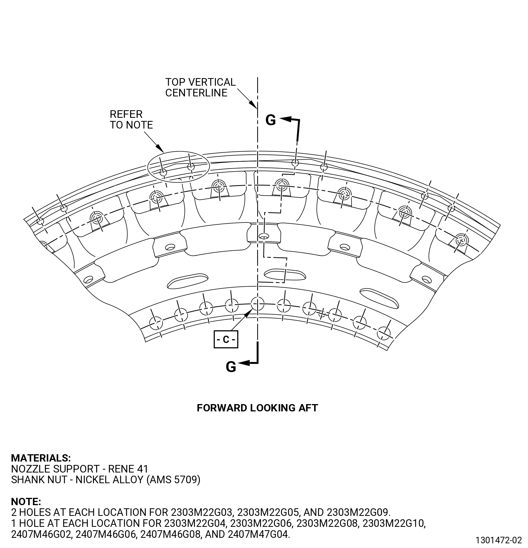
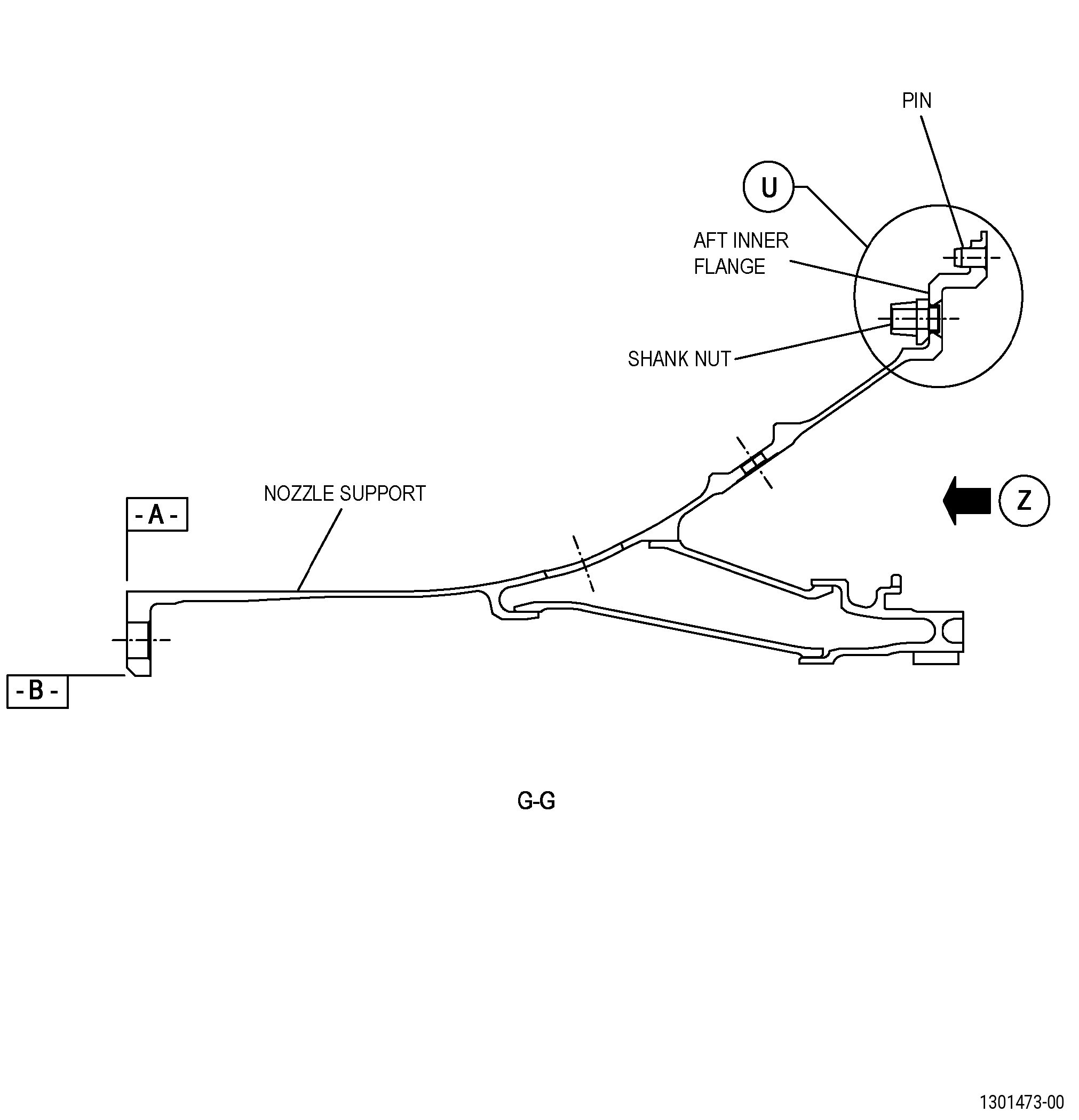
| A. | This procedure gives instructions to repair the high pressure turbine stage 1 nozzle support (nozzle support) by replacing damaged or missing self-locking shank nuts (shank nuts). Refer to Figure 901 and Figure 902. |
| B. | The following maximum repairable limits apply to this repair: |
| NOTE: |
|
| NOTE: |
|
| (4) | Visual Inspection. |
| (c) | Do an inspection of the forward flange, combustor flange interface, and aft inner flange for: |
| 5 | Loose or missing shank nuts: |
| Maximum repairable limit: |
|
| C. | The subsequent table gives a list of the part numbers that are applicable to this repair. All part numbers are applicable to all paragraphs unless specified differently. |
|
|||||||||||||||||||||||||||||||||||||||||||||||||
| D. | Proprietary/Complex Process Statement. |
| (1) | None. |
| 2 . | Tools, Equipment, and Materials. |
| NOTE: |
|
| A. | Tools and Equipment. |
| (1) | Special Tools. None. |
| (2) | Standard Tools and Equipment. None. |
| (3) | Locally Manufactured Tools. None. |
| B. | Consumable Materials. |
|
| C. | Referenced Procedures. |
| D. | Expendable Parts. None. |
| E. | SPD Information. |
|
| F. | Special Solutions. None. |
| G. | Test Specimens. None. |
| 3 . | Dimensional Information. |
| Subtask 72-51-01-220-042 |
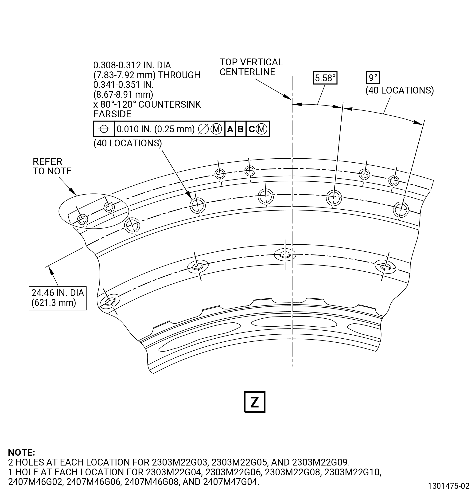
| A. | Refer to Figure 901 and Figure 902 for specified dimensions and locations. |
| NOTE: |
|
| 4 . | Setup Information. |
| Subtask 72-51-01-350-001 |
| A. | Set-up the nozzle support for machining as follows: |
| (1) | Put the nozzle support forward end down on a machine table. |
| (2) | Attach the nozzle support forward flange to the machine table with clamps as follows: |
| (a) | Keep surface A flat to 0.002 inch (0.05 mm) or better. |
| (3) | Put the machine spindle directly above the center of the nozzle support shank nut hole that you will repair and do as follows: |
| (a) | Lock the machine spindle in place. |
| 5 . | Procedure. |
| Subtask 72-51-01-160-001 |
| A. | Clean the nozzle support. Refer to TASK 72-51-01-100-801 (72-51-01, CLEANING 001). |
| Subtask 72-51-01-350-002 |
| B. | Remove the damaged shank nut(s) from the nozzle support as follows: |
| (1) | Set-up the nozzle support for machining. Refer to Substak 72-51-01-350-001 (paragraph 4.A., Setup Information). |
| Subtask 72-51-01-320-001 |
| (2) | Machine the shank nut(s). Refer to TASK 70-00-03-800-004 (MACHINING DATA) and as follows: |
| CAUTION: |
|
| (a) | Drill a hole at the flared end of the nozzle support shank nut as follows: |
| NOTE: |
|
| 1 | Drill the hole to a diameter of 0.308 inch (7.82 mm) or less. |
| 2 | Drill the hole to a depth of 0.120-0.140 inch (3.05-3.55 mm). |
| Subtask 72-51-01-350-003 |
| CAUTION: |
|
| (b) | If necessary, use a tapered punch and a mallet to release the shank nut from the nozzle support. |
| (c) | Remove the shank nut from the nozzle support. |
| (d) | Discard all of the shank nuts that you remove. |
| Subtask 72-51-01-110-008 |
| C. | If necessary, clean the nozzle support. Refer to TASK 72-51-01-100-801 (72-51-01, CLEANING 001) and as follows: |
| NOTE: |
|
| WARNING: |
|
| (1) | Use a clean C10-182 lint free cloth moist with C04-035 isopropyl alcohol to clean the local repair areas that you will examine. |
| Subtask 72-51-01-230-003 |
| D. | Do an inspection of the nozzle support. Refer to TASK 70-32-00-200-002 (INDIRECT INSPECTION METHODS), TASK 70-32-03-230-002 (SPOT-FLUORESCENT-PENETRANT INSPECTION), and as follows: |
| (1) | Use Class C penetrant. |
| (2) | Examine the nozzle support shank nut holes that do not have a shank nut installed and the surfaces adjacent to the nozzle support shank nut holes. |
| (3) | Refer to TASK 70-31-02-220-003 (ACCEPTABILITY LIMITS FOR FLUORESCENT PENETRANT INSPECTION) and as follows: |
| (a) | Use Class A limits. |
| Subtask 72-51-01-220-043 |
| E. | Do an inspection of the nozzle support shank nut holes. Refer to Figure 901, Figure 902, and as follows: |
| (1) | Do a dimensional inspection of the nozzle support shank nut holes that do not have a shank nut installed. |
| NOTE: |
|
| Subtask 72-51-01-350-004 |
| F. | Install the spare shank nut(s), 9114M97P19 , on the nozzle support. Refer to TASK 70-48-00-350-015 (THREADED INSERTS), TASK 70-48-13-350-024 (SHANK NUT REPAIR), Figure 901, and as follows: |
| (1) | Make sure that the spare shank nut is correctly attached to the nozzle support as follows: |
| (a) | The installed shank nut lug must be flush with the forward surface of the nozzle support aft inner flange as follows: |
| 1 | Flare the spare shank nut until the axial movement is 0.005 inch (0.12 mm) or less. |
| 2 | Use a shim that is 0.005 inch (0.12 mm) or less in thickness to do a check of the axial movement. |
| 3 | The fit of the shim between the nozzle support aft inner flange and the shank nut lug is permitted to be tight. |
| Subtask 72-51-01-220-044 |
| (2) | Do an inspection of the installed spare shank nut(s). Refer to TASK 70-32-00-200-002 (INDIRECT INSPECTION METHODS), TASK 70-32-11-220-011 (WHITE LIGHT INSPECTION) , and as follows: |
| (a) | Make sure there are no linear indications in the shank of the installed shank nut(s). |
| NOTE: |
|
| (b) | Use 10x magnification. |
| (c) | If you find linear indications in the shank of the shank nut, do as follows: |
| 1 | Do Subtask 72-51-01-350-002 (paragraph 5.B.) thru Subtask 72-51-01-350-004 (paragraph 5.F.) again until the shank nut holes and the installed shank nuts agree with the limits. |
| Subtask 72-51-01-350-005 |
| G. | Deleted. |
| Subtask 72-51-01-160-002 |
| H. | Clean the nozzle support. Refer to TASK 72-51-01-100-801 (72-51-01, CLEANING 001). |
| Subtask 72-51-01-200-001 |
| I. | Do an inspection of the nozzle support. Refer to TASK 72-51-01-200-801 (72-51-01, INSPECTION 001). |