| GENX-1B CLEANING,INSPECTION,AND REPAIR MANUAL | Dated: 11/26/2020 | |
| CIR 72-51-01 , REPAIR 011 | ||
| HIGH PRESSURE TURBINE FORWARD INNER NOZZLE SUPPORT - REPAIR - CHROME CARBIDE EROSION COATING REPAIR | ||
| GENX-1B CLEANING,INSPECTION,AND REPAIR MANUAL | Dated: 11/26/2020 | |
| CIR 72-51-01 , REPAIR 011 | ||
| HIGH PRESSURE TURBINE FORWARD INNER NOZZLE SUPPORT - REPAIR - CHROME CARBIDE EROSION COATING REPAIR | ||
| * * * FOR ALL |
| TASK 72-51-01-300-811 |
| 1 . | Chrome Carbide Erosion Coating Repair. |
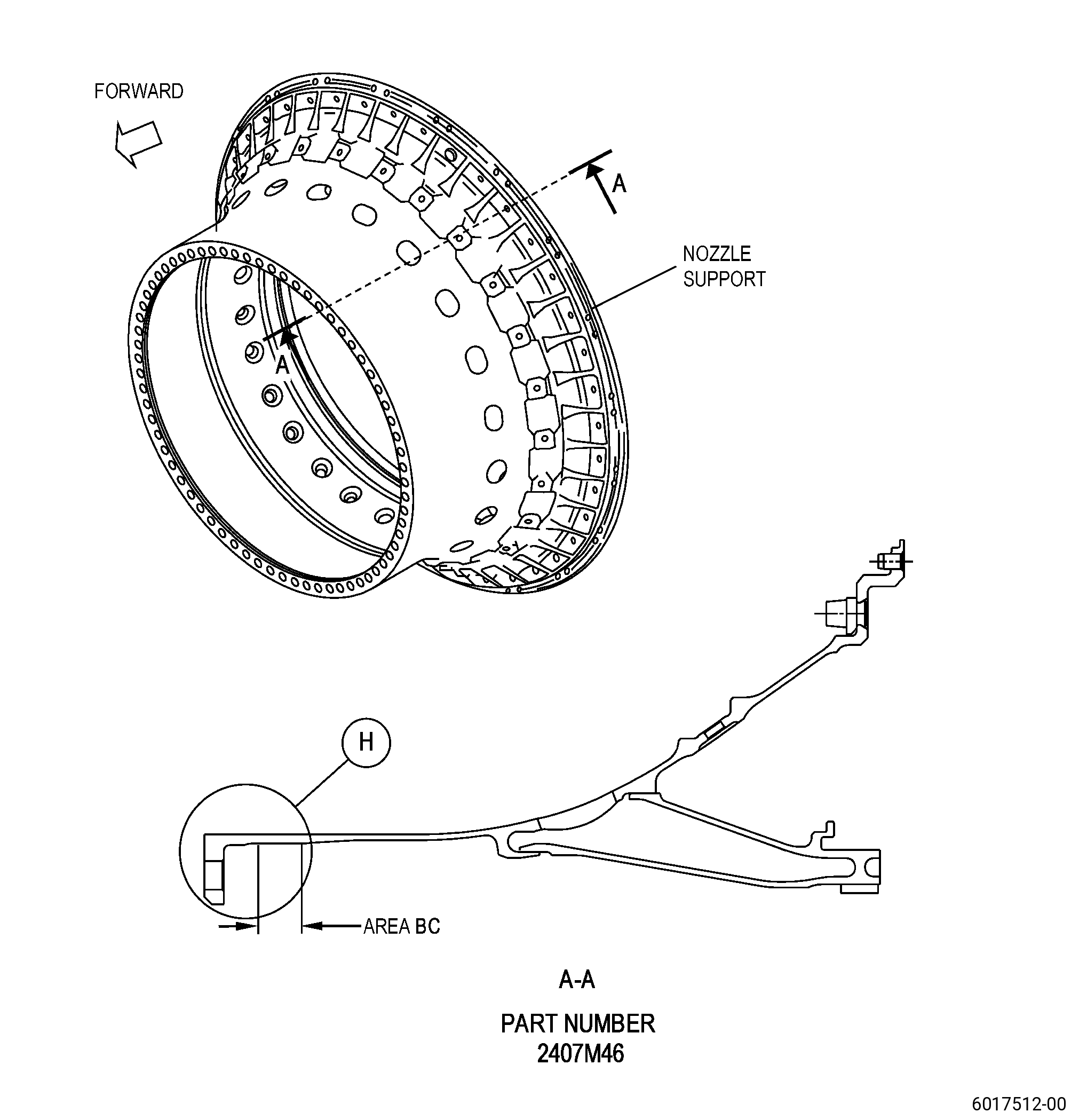
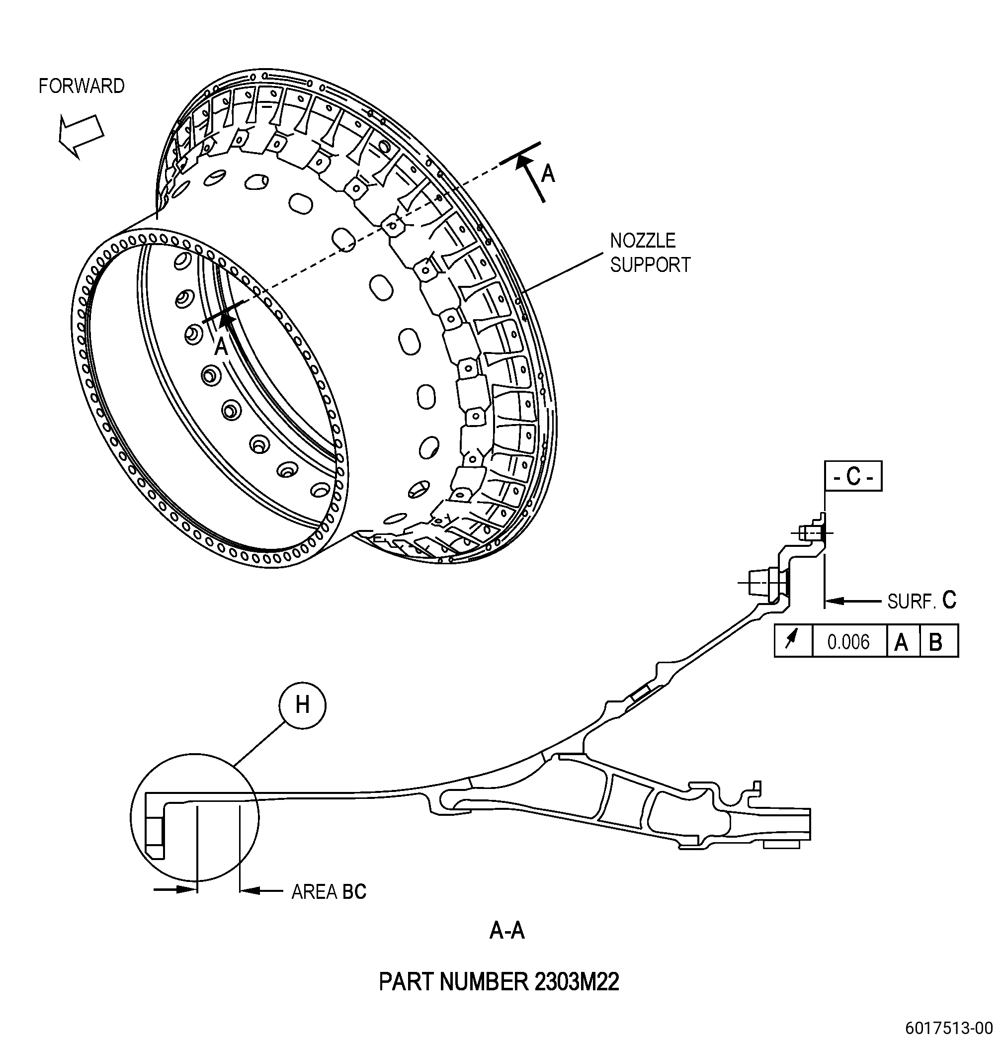
| A. | This procedure gives instructions to repair the high pressure turbine forward inner nozzle support (nozzle support) erosion coating by machining or by water jet and re-applying the coating to area BC with a thermal spray. Refer to Figure 901. |
| B. | The following maximum repairable limits apply to this repair: |
| NOTE: |
|
| (4) | Visual Inspection. |
| (h) | Do an inspection of the inner diameter of the forward flange area. Refer to Figure 802 and as follows: |
| * * * SB 72-0359 |
| 3 | Missing, eroded or damage hard coat in area BC: |
| Maximum repairable limit: |
|
| C. | The subsequent table gives a list of the part numbers that are applicable to this procedure. All part numbers are applicable to all paragraphs unless specified differently. |
|
||||||||||||||||||||||||||||||||||||
| D. | Proprietary/Complex Process Statement. |
| (1) | None. |
| 2 . | Tools, Equipment, and Materials. |
| NOTE: |
|
| A. | Tools and Equipment. |
| (1) | Special Tools. None. |
| (2) | Standard Tools and Equipment. None. |
| (3) | Locally Manufactured Tools. None. |
| B. | Consumable Materials. |
|
| C. | Referenced Procedures. |
| D. | Expendable Parts. None. |
| E. | SPD Information. |
| (1) | Spare Supplied. None. |
| (2) | Protected Spares. None. |
| (3) | Locally Manufactured Spares. None. |
| F. | Special Solutions. None. |
| G. | Test Specimens. |
|
| 3 . | Dimensional Information. |
| Subtask 72-51-01-220-111 |
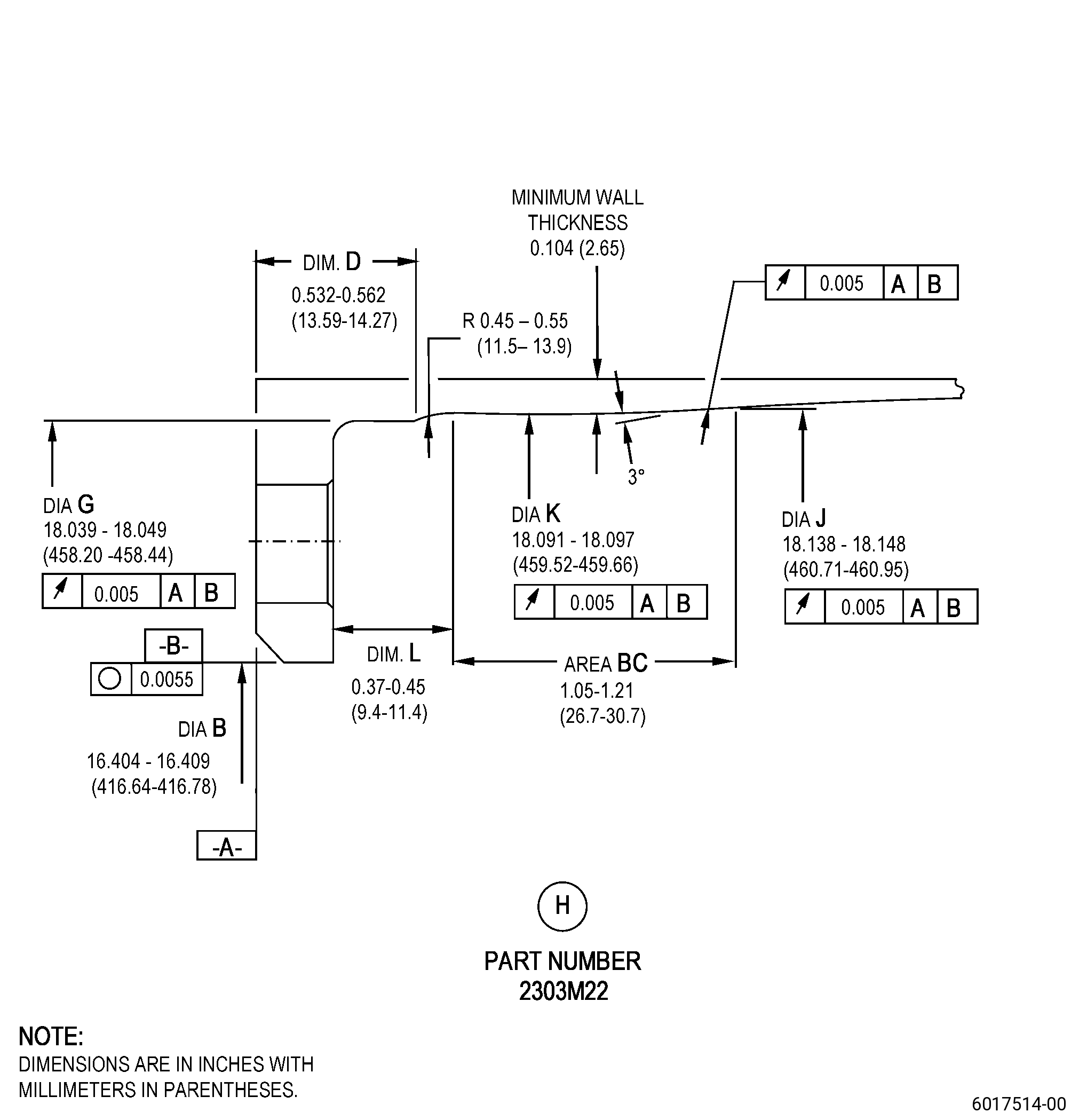
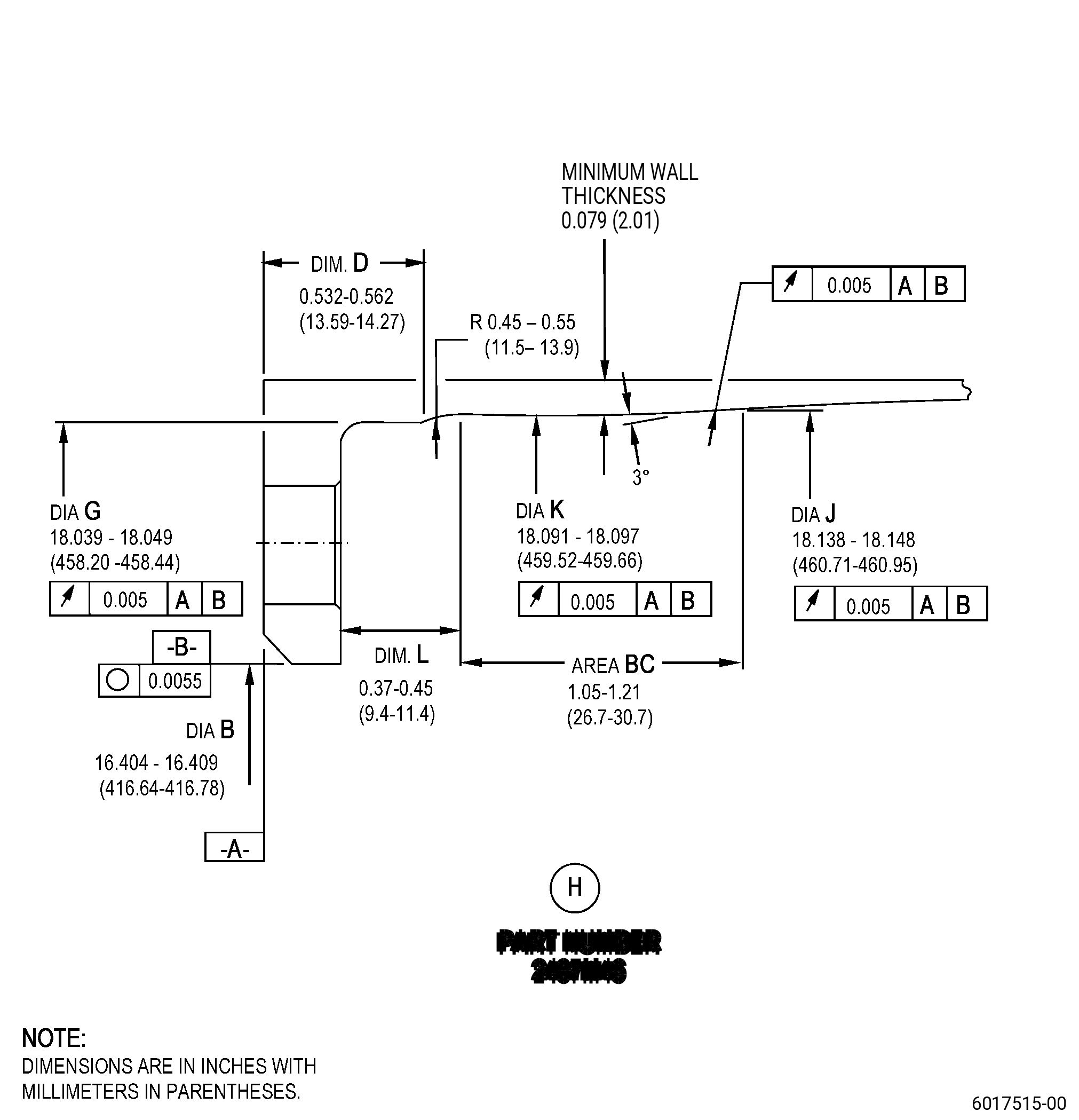
| A. | Refer to Figure 901 for specified dimensions and locations. |
| NOTE: |
|
| NOTE: |
|
| 4 . | Setup Information. |
| None. |
| 5 . | Procedure. |
| Subtask 72-51-01-160-023 |
| A. | If necessary, clean the nozzle support. Refer to TASK 72-51-01-100-801 (72-51-01, CLEANING 001). |
| Subtask 72-51-01-320-016 |
| B. | Alternative Procedure Available. Machine to remove the chrome carbide coating from the nozzle support area BC. Refer to TASK 70-00-03-800-004 (MACHINING DATA), Subtask 72-51-01-220-011 (paragraph 3.A.), and Figure 901. |
| (1) | Adjust the position of the nozzle support to get surface C (datum C) flat, and to agree with the limits. Refer to Figure 901. |
| (2) | Adjust the position of the nozzle support to get the diameter of surface B (datum B) to agree with the limits. Refer to Figure 901. |
| CAUTION: |
|
| (3) | Machine the area BC. |
| (4) | Remove the remaining areas of coating by blending. Refer to TASK 70-42-00-350-002 (BLENDING AND REMOVAL OF HIGH METAL PROCEDURES). |
| (5) | For PN 2303M22, do the wall thickness inspection in area BC. The minimum wall thickness must be 0.104 inch (2.65 mm). |
| (6) | For PN 2407M46, do the wall thickness inspection in area BC. The minimum wall thickness must be 0.079 inch (2.01 mm). |
| Subtask 72-51-01-330-001 |
| B.A. | Alternative Procedure. Remove the chrome carbide coating from the nozzle support area BC. Refer to TASK 70-23-00-100-001 (STRIPPING PROCEDURES), TASK 70-23-23-330-008 (REMOVAL OF COATINGS BY HIGH PRESSURE WATER STRIPPING), and Figure 901. |
| CAUTION: |
|
| (1) | Remove from area BC. |
| (2) | Deleted. |
| (3) | For PN 2303M22, do the wall thickness inspection in area BC. The minimum wall thickness must be 0.104 inch (2.65 mm). |
| (4) | For PN 2407M46, do the wall thickness inspection in area BC. The minimum wall thickness must be 0.079 inch (2.01 mm). |
| Subtask 72-51-01-160-024 |
| C. | Clean the nozzle support. Refer to TASK 72-51-01-100-801 (72-51-01, CLEANING 001). |
| Subtask 72-51-01-110-038 |
| D. | Etch the nozzle support machined areas. Refer to TASK 70-24-00-110-033 (ETCHING PROCEDURES FOR FLUORESCENT-PENETRANT INSPECTION), TASK 70-24-01-110-034 (SWAB ETCHING PROCEDURE), and as follows: |
| (1) | Use Class C etchant. |
| Subtask 72-51-01-230-032 |
| E. | Do an inspection of the nozzle support. Refer to TASK 70-32-00-200-002 (INDIRECT INSPECTION METHODS), TASK 70-32-02-230-001 (FLUORESCENT PENETRANT INSPECTION), Figure 901, and as follows: |
| (1) | Use Class C penetrant. |
| (a) | Indications 0.030 inch (0.76 mm) or less are not interpretable and are permitted. |
| (b) | Non-linear indications 0.060 inch (1.52 mm) or less with a minimum distance of between indications of 0.15 inch (3.9 mm) are permitted. |
| (c) | Linear indications more than 0.030 inch (0.76 mm) are not permitted. |
| NOTE: |
|
| (d) | Through indications are not permitted. |
| (e) | For PN 2407M46, microshrinkage must agree with GEAE Photo Standard 8311253, Class 30. |
| Subtask 72-51-01-220-112 |
| F. | Do a visual inspection of the nozzle support into the parent material to make sure that there is no erosion. Refer to Figure 901 and as follows: |
| (1) | Part needs to be serviceable, refer to TASK 72-51-01-200-801 (72-51-01, INSPECTION 001) section. |
| (2) | If there is erosion into the parent material for other areas, you must not repair the nozzle support with this procedure. |
| Subtask 72-51-01-160-025 |
| G. | If necessary, clean the nozzle support. Refer to TASK 72-51-01-100-801 (72-51-01, CLEANING 001). |
| Subtask 72-51-01-340-001 |
| H. | Apply a chrome carbide coating to area BC on the internal diameter of the forward section of the nozzle support body. Refer to Figure 901 and as follows: |
| (1) | Use C10-012 tape to mask all internal openings and cavities of the inducer and honeycomb seal to keep dirt and unwanted material out. |
| (2) | Use C10-012 tape to mask all surfaces adjacent to area BC. |
| (3) | Prepare test specimens for coating application. Refer to TASK 70-70-00-700-001 (TESTING AND QUALITY ANALYSIS), table 2, and as follows: |
| (a) | Put the test specimens in an area that will allow them to receive the same amount of coating as does the part. |
| (4) | Apply thermal spray to area BC with C07-027 chromium carbide powder. Refer to TASK 70-49-00-340-001 (THERMAL SPRAYING), TASK 70-49-29-340-030 (THERMAL SPRAYING 75 PERCENT CHROMIUM CARBIDE - 25 PERCENT NICKEL CHROMIUM (POWDER)), and as follows: |
| (a) | The thickness of the chrome carbide coating must be 0.007-0.010 inch (0.18-0.25 mm). |
| (b) | If necessary, blend the surface to remove the loose particles. Refer to TASK 70-42-00-350-002 (BLENDING AND REMOVAL OF HIGH METAL PROCEDURES). |
| (5) | Do all the quality assurance tests. Refer to TASK 70-49-29-340-030 (THERMAL SPRAYING 75 PERCENT CHROMIUM CARBIDE - 25 PERCENT NICKEL CHROMIUM (POWDER)). |
| Subtask 72-51-01-160-026 |
| I. | If necessary, clean the nozzle support. Refer to TASK 72-51-01-100-801 (72-51-01, CLEANING 001). |
| Subtask 72-51-01-220-113 |
| J. | Do a visual inspection of the thermal spray coating and adjacent coated surfaces for bond and surface condition. Refer to TASK 70-49-29-340-030 (THERMAL SPRAYING 75 PERCENT CHROMIUM CARBIDE - 25 PERCENT NICKEL CHROMIUM (POWDER)). |
| Subtask 72-51-01-220-114 |
| K. | Do a final inspection of the nozzle support. Refer to TASK 72-51-01-200-801 (72-51-01, INSPECTION 001). |