| GENX-1B CLEANING,INSPECTION,AND REPAIR MANUAL | Dated: 07/01/2020 | |
| CIR 72-51-01 , REPAIR 005 | ||
| HIGH PRESSURE TURBINE STAGE 1 NOZZLE SUPPORT - REPAIR - BRAZE VOIDING RESTORATION | ||
| GENX-1B CLEANING,INSPECTION,AND REPAIR MANUAL | Dated: 07/01/2020 | |
| CIR 72-51-01 , REPAIR 005 | ||
| HIGH PRESSURE TURBINE STAGE 1 NOZZLE SUPPORT - REPAIR - BRAZE VOIDING RESTORATION | ||
| * * * FOR ALL |
| TASK 72-51-01-300-805 |
| 1 . | Braze Voiding Restoration. |
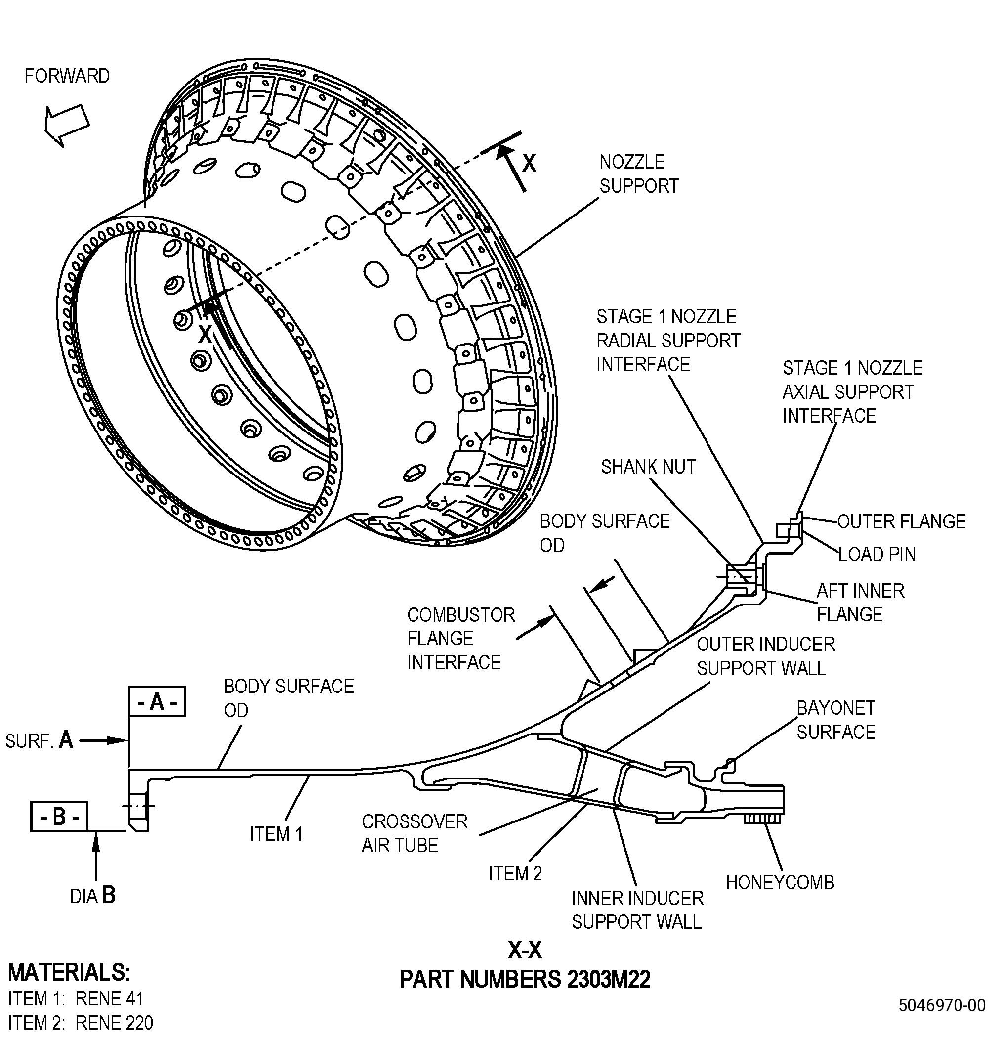
| A. | This procedure gives instructions to repair the high pressure turbine stage 1 nozzle support (nozzle support) by brazing the nozzle support again to restore braze areas. Refer to Figure 901. |
| B. | The following maximum repairable limits apply to this repair: |
| NOTE: |
|
| (4) | Visual Inspection. |
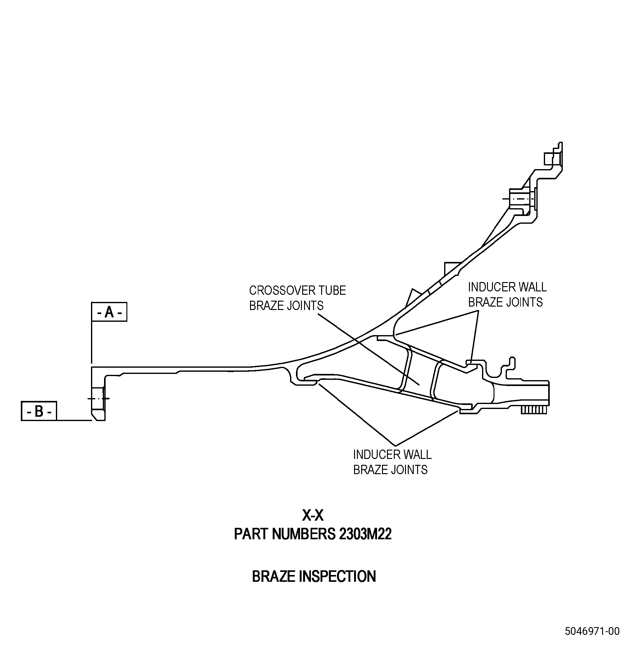
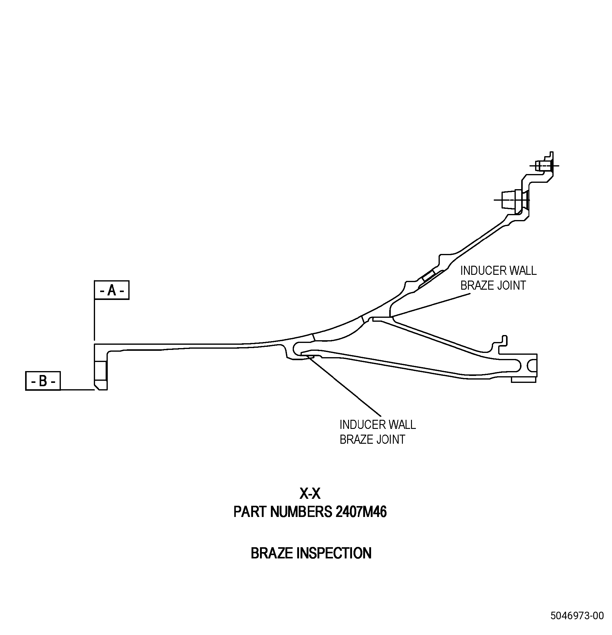
| (d) | Do an inspection of the braze joints (inner and outer support wall) for: |
| 1 | Braze voids and cracks: |
| Maximum repairable limit: |
|
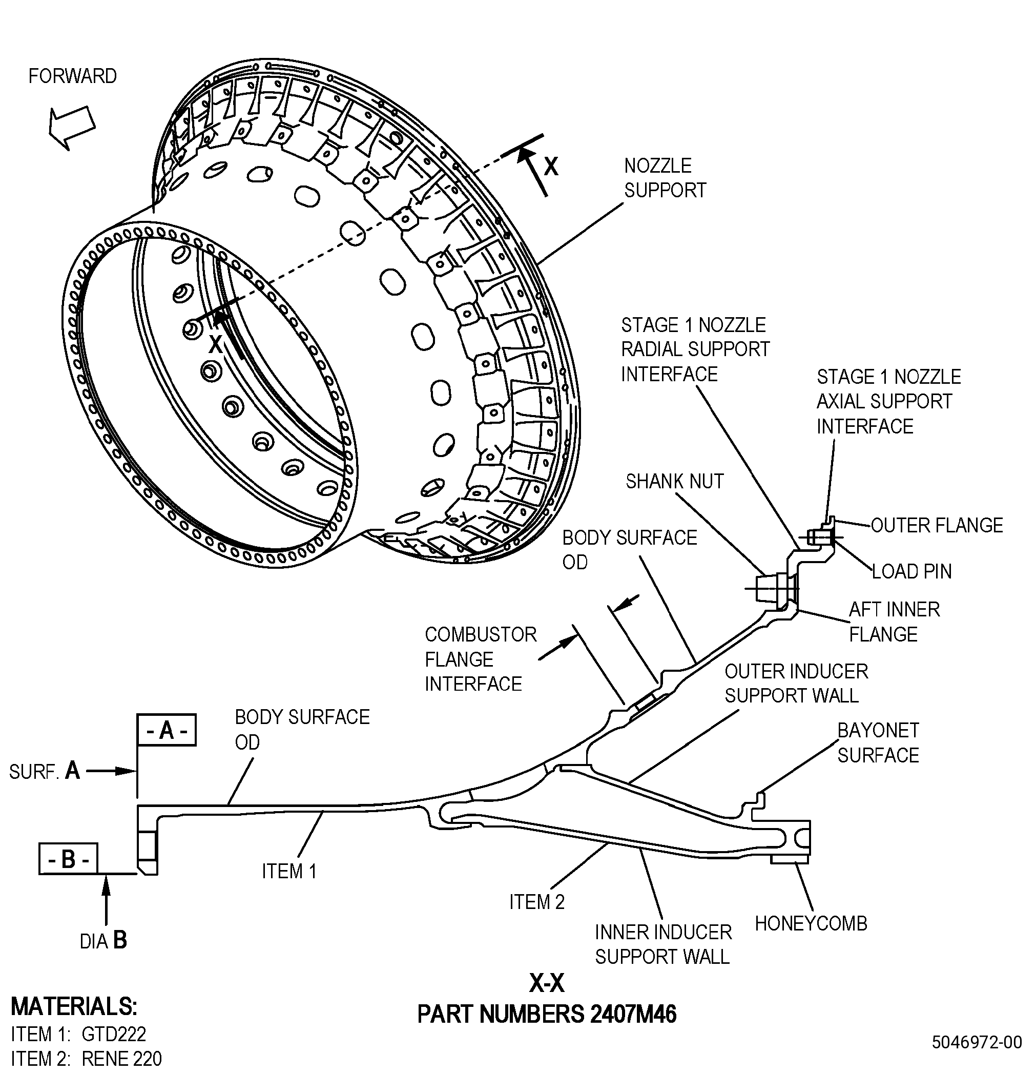
| C. | The subsequent table gives a list of the part numbers that are applicable to this repair. All part numbers are applicable to all paragraphs unless specified differently. |
|
||||||||||||||||||||||||||||||||||||
| D. | Proprietary/Complex Process Statement. |
| (1) | None. |
| 2 . | Tools, Equipment, and Materials. |
| NOTE: |
|
| A. | Tools and Equipment. |
| (1) | Special Tools. None. |
| (2) | Standard Tools and Equipment. None. |
| (3) | Locally Manufactured Tools. |
|
| B. | Consumable Materials. |
| C. | Referenced Procedures. |
|
| D. | Expendable Parts. None. |
| E. | SPD Information. |
| (1) | Locally Manufactured SPD. None. |
| F. | Special Solutions. None. |
| G. | Test Specimens. None. |
| 3 . | Dimensional Information. |
| Subtask 72-51-01-220-071 |
| A. | Refer to Figure 901 for specified dimensions and locations. |
| NOTE: |
|
| NOTE: |
|
| 4 . | Setup Information. |
| Subtask 72-51-01-350-053 |
| A. | Set-up the nozzle support for heat treatment/brazing as follows: |
| Subtask 72-51-01-930-004 |
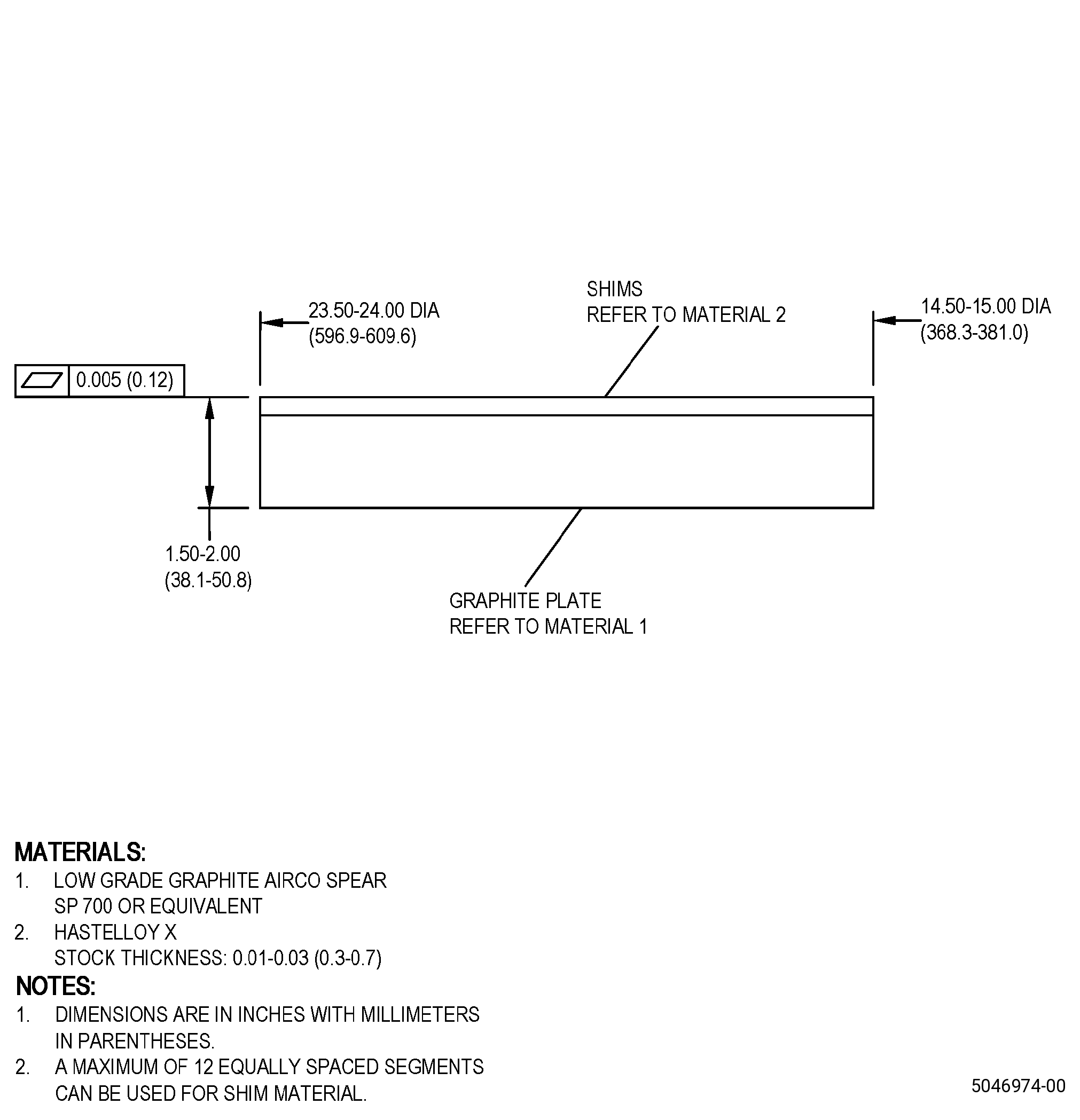
| (1) | If necessary, make the heat treatment/brazing fixture. Refer to Figure 902. |
| Subtask 72-51-01-350-054 |
| (2) | Install the heat treatment/brazing fixture as follows: |
| (a) | Put the graphite plate on a furnace grid. |
| (b) | Put shims on top of the graphite plate. |
| (3) | Put the nozzle support forward flange on top of the shims. |
| Subtask 72-51-01-370-010 |
| (4) | For the quantity and placement requirements of the load thermocouples, refer to TASK 70-44-03-370-004 (FURNACE HEAT TREATMENT) . |
| 5 . | Procedure. |
| Subtask 72-51-01-110-026 |
| A. | If necessary, clean the nozzle support. Refer to TASK 72-51-01-100-801 (72-51-01, CLEANING 001). |
| Subtask 72-51-01-350-055 |
| B. | Remove the shank nuts from the nozzle support. Refer to TASK 72-51-01-300-801 (72-51-01, REPAIR 001). |
| Subtask 72-51-01-350-117 |
| C. | For part numbers 2407M46G06 and 2407M46G08 , remove the hard coating from the nozzle support. Refer to TASK 72-51-01-300-811 (72-51-01, REPAIR 011). |
| Subtask 72-51-01-350-056 |
| D. | Prepare the nozzle support joints to apply braze alloy again as follows: |
| (1) | Use carbide burr to remove oxidation from the braze joints or equivalent. |
| Subtask 72-51-01-110-027 |
| WARNING: |
|
| CAUTION: |
|
| (2) | Clean the braze joints area with a clean C10-182 cleaning cloth moist with C04-035 isopropyl alcohol. |
| Subtask 72-51-01-110-028 |
| E. | If necessary, clean the nozzle support. Refer to TASK 72-51-01-100-801 (72-51-01, CLEANING 001). |
| Subtask 72-51-01-350-057 |
| WARNING: |
|
| F. | Optional Procedure. Put the nozzle support in an oven at a temperature range of 130 to 150°F (54 to 66°C) for 30 minutes minimum to remove all moisture. |
| Subtask 72-51-01-350-058 |
| G. | Apply the braze slurry to the nozzle support as follows: |
| (1) | Make a slurry as follows: |
| (a) | Use C06-014 braze alloy. |
| (b) | Use C06-019 binder. |
| (2) | Apply a braze slurry bead of approximately 0.062-0.120 inch (1.58-3.04 mm) in diameter as necessary to braze the nozzle support repair areas again. |
| Subtask 72-51-01-350-059 |
| WARNING: |
|
| H. | Apply C10-015 braze stop-off to the nozzle support areas adjacent to the braze joints to prevent braze flow during the brazing procedure. |
| Subtask 72-51-01-310-008 |
| I. | Braze the nozzle support. Refer to TASK 70-41-00-310-001 (WELDING AND BRAZING PRACTICES), TASK 70-41-03-310-004 (HIGH TEMPERATURE FURNACE BRAZE), and as follows: |
| (1) | Set-up the nozzle support for heat treatment/brazing. Refer to Subtask 72-51-01-350-053 (paragraph 4.A.). |
| (2) | Put the heat treatment/brazing fixture and the nozzle support in the furnace. |
| (3) | Increase the temperature of the nozzle support to a temperature range of 1700 to 1750°F (927 to 954°C) and as follows: |
| (a) | Keep this temperature for 10-15 minutes or until the vacuum rate gets back to a vacuum pressure of 5.0 X 10⁻⁴ mm Hg or less. |
| CAUTION: |
|
| (4) | Increase the temperature of the nozzle support to a temperature range of 1875 to 1925°F (1024 to 1052°C) at a rate of 20 to 25°F (11 to 14°C) for each minute and as follows: |
| (a) | Keep this temperature for a maximum of 3-5 minutes. |
| NOTE: |
|
| (5) | Decrease the temperature of the nozzle support to a temperature range of 1750 to 1800°F (954 to 982°C) at a minimum rate of 20°F (11°C) for each minute and as follows: |
| (a) | Keep this temperature for 10-15 minutes. |
| (6) | Decrease the temperature of the nozzle support to 975 to 1025°F (524 to 552°C) within 30 minutes or less. |
| NOTE: |
|
| WARNING: |
|
| (7) | Remove the nozzle support from the furnace. |
| Subtask 72-51-01-220-072 |
| J. | Do a visual inspection of the nozzle support braze joints. Refer to Figure 901 and as follows: |
| (1) | The two sides of the braze joints must show braze material fully around the braze joint. |
| (2) | Through voids are not permitted. |
| (3) | Irregular fillets and pinholes (surface porosity) are permitted. |
| (4) | Indications 0.015 inch (0.38 mm) or less are permitted. |
| (5) | The diameter or length of each void or unbounded area must not be more than 0.080 inch (2.03 mm). |
| (6) | Local or continuous concavity is permitted. |
| (7) | The minimum distance between adjacent voids or unbonded areas must be two times the size of the largest adjacent void or unbonded area. |
| (8) | There must be three voids or unbonded areas or less for each 1.0 inch (25 mm) of braze material. |
| (9) | Braze overflow is permitted as follows: |
| (a) | A maximum height of 0.005 inch (0.12 mm) for braze overflow is permitted on the parent metal at a distance of 0.150 inch (3.81 mm) or more from the braze joint. |
| Subtask 72-51-01-350-060 |
| K. | If necessary, repair the nozzle support incorrect braze area as follows: |
| (1) | Do Subtask 72-51-01-350-058 (paragraph 5.F.) thru Subtask 72-51-01-220-072 (paragraph 5.I.) again. |
| NOTE: |
|
| Subtask 72-51-01-220-073 |
| L. | Do an inspection of the honeycomb. Refer to TASK 72-51-01-300-802 (72-51-01, REPAIR 002) (paragraph 5.R. or paragraph 5.R.A.) and as follows: |
| (1) | If necessary, repair the unacceptable honeycomb braze area. Refer to TASK 72-51-01-300-802 (72-51-01, REPAIR 002). |
| Subtask 72-51-01-370-011 |
| M. | Do a heat treatment of the nozzle support. Refer to TASK 70-44-00-800-010 (HEAT TREATING), TASK 70-44-03-370-004 (FURNACE HEAT TREATMENT), and as follows: |
| (1) | For part numbers 2303M22G03 , 2303M22G04 , 2303M22G05 , and 2303M22G06 , do a heat treatment of the nozzle support as follows: |
| (a) | Set-up the nozzle support for heat treatment/brazing. Refer to Subtask 72-51-01-350-053 (paragraph 4.A.). |
| (b) | Put the nozzle support and the heat treatment/brazing fixture in the furnace. |
| (c) | Heat-treat the nozzle support. Refer to TASK 70-44-00-800-010 (HEAT TREATING), TASK 70-44-03-370-004 (FURNACE HEAT TREATMENT) , and as follows: |
| 1 | Do an age heat treatment of the nozzle support as follows: |
| a | Use Cycle V-13 or Cycle I-9. |
| (2) | For part numbers 2407M46G02 , 2407M46G04 , 2407M46G06 , and 2407M46G08 , do a heat treatment of the nozzle support as follows: |
| (a) | Set-up the nozzle support for heat treatment/brazing. Refer to Subtask 72-51-01-350-053 (paragraph 4.A.). |
| (b) | Put the nozzle support and the heat treatment/brazing fixture in the furnace. |
| (c) | Heat-treat the nozzle support. Refer to TASK 70-44-00-800-010 (HEAT TREATING), TASK 70-44-03-370-004 (FURNACE HEAT TREATMENT) , and as follows: |
| 1 | Do an age heat treatment of the nozzle support as follows: |
| a | Age the nozzle support at 1450 to 1500°F (788 to 816°C) for 8 hours. |
| WARNING: |
|
| b | Decrease the temperature of the nozzle support to 1000°F (538°C) with cool nitrogen, helium, or argon gas at a rate not less than 25°F (13.89°C) for each minute. |
| c | Decrease the temperature of the nozzle support to room temperature. |
| d | Remove the nozzle support from the furnace. |
| Subtask 72-51-01-350-118 |
| N. | For part numbers 2407M46G06 and 2407M46G08 , apply the hard coating from the nozzle support. Refer to TASK 72-51-01-300-811 (72-51-01, REPAIR 011). |
| Subtask 72-51-01-230-013 |
| O. | Do an inspection of the nozzle support. Refer to TASK 70-32-00-200-002 (INDIRECT INSPECTION METHODS), TASK 70-32-02-230-001 (FLUORESCENT PENETRANT INSPECTION), Figure 901, and as follows: |
| (1) | Use Class C penetrant. |
| (2) | For part number 2303M22 item 1 only. Refer to TASK 70-31-02-220-003 (ACCEPTABILITY LIMITS FOR FLUORESCENT PENETRANT INSPECTION) , for the acceptance limits and as follows: |
| (a) | Use Class A limits. |
| (3) | For other items of part number 2303M22 and all items of part number 2407M46 , use the acceptability limits that follow: |
| (a) | Indications 0.030 inch (0.76 mm) or less are not interpretable and are permitted. |
| (b) | Non-linear indications 0.060 inch (1.52 mm) or less with a minimum distance of between indications of 0.15 inch (3.9 mm) are permitted. |
| (c) | Linear indications more than 0.030 inch (0.76 mm) are not permitted. |
| NOTE: |
|
| (d) | Through indications are not permitted. |
| (e) | Microshrinkage must agree with GEAE Photo Standard 8311253, Class 30. |
| Subtask 72-51-01-220-074 |
| P. | Do a dimensional inspection of the nozzle support. Refer to TASK 72-51-01-200-801 (72-51-01, INSPECTION 001). |
| Subtask 72-51-01-350-061 |
| Q. | Install the shank nuts to the nozzle support. Refer to TASK 72-51-01-300-801 (72-51-01, REPAIR 001). |