| GENX-1B CLEANING,INSPECTION,AND REPAIR MANUAL | Dated: 10/31/2022 | |
| CIR 72-51-01 , REPAIR 004 | ||
| HIGH PRESSURE TURBINE STAGE 1 NOZZLE SUPPORT - REPAIR - WELD REPAIR OF OUTER FLANGE CRACKS | ||
| GENX-1B CLEANING,INSPECTION,AND REPAIR MANUAL | Dated: 10/31/2022 | |
| CIR 72-51-01 , REPAIR 004 | ||
| HIGH PRESSURE TURBINE STAGE 1 NOZZLE SUPPORT - REPAIR - WELD REPAIR OF OUTER FLANGE CRACKS | ||
| * * * FOR ALL |
| TASK 72-51-01-300-804 |
| 1 . | Weld Repair of Outer Flange Cracks. |
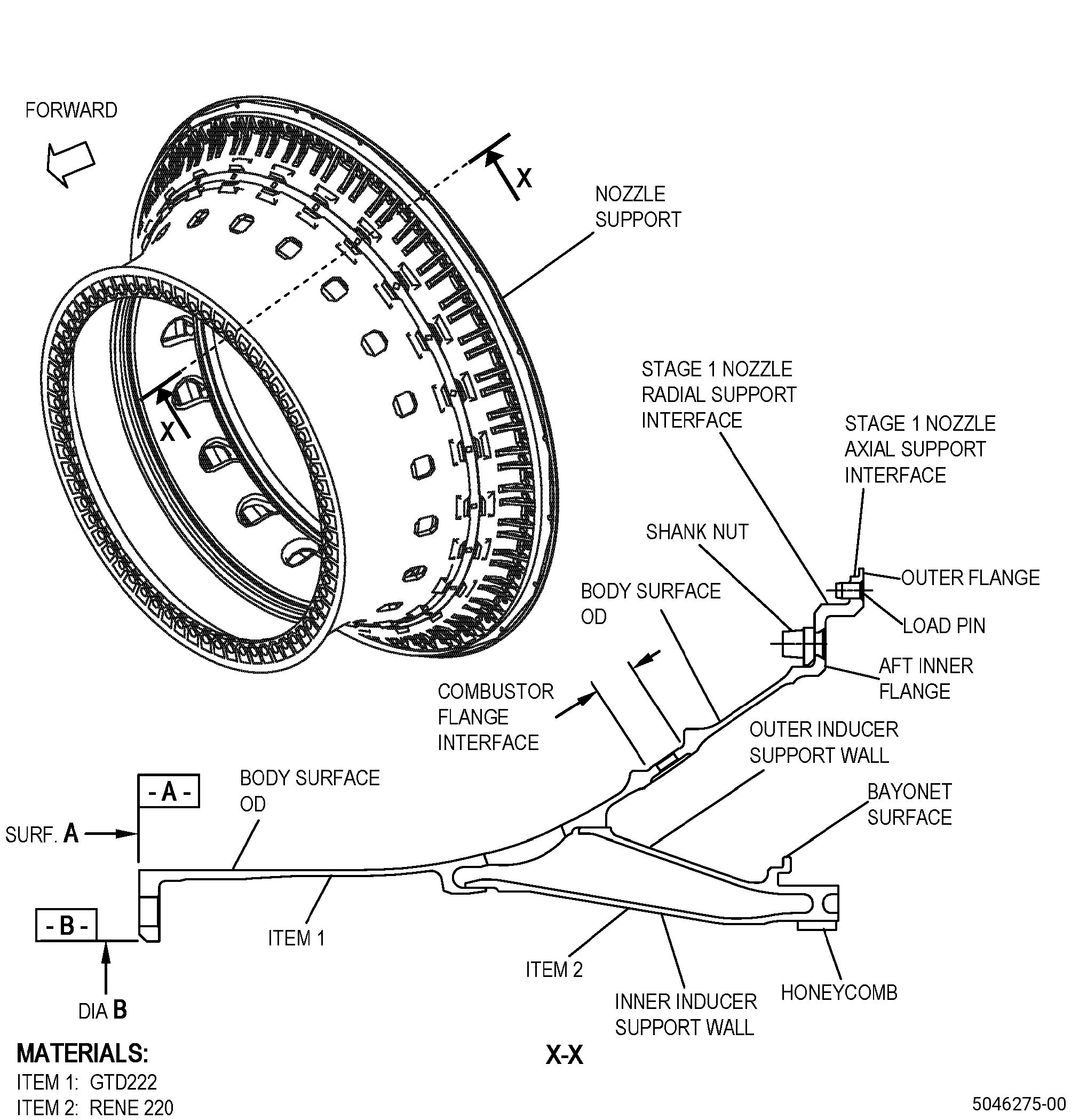
| A. | This procedure gives instructions to repair the high pressure turbine stage 1 nozzle support (nozzle support) by welding cracks on the outer flange. Refer to Figure 901. |
| B. | The following maximum repairable limits apply to this repair: |
| NOTE: |
|
| (4) | Visual Inspection. |
| (b) | Do an inspection of the outer flange area for: |
| 2 | Radial cracks from the outer diameter: |
| Maximum repairable limit: |
|
| (c) | Measure dimension D: |
| Maximum repairable limit: |
|
| (d) | Runout at diameter BA: |
| Maximum repairable limit: |
|
| C. | The subsequent table gives a list of the part numbers that are applicable to this repair. All part numbers are applicable to all paragraphs unless specified differently. |
|
||||||||||||||||||||||||||||||||||||
| D. | Proprietary/Complex Process Statement. |
| (1) | None. |
| 2 . | Tools, Equipment, and Materials. |
| NOTE: |
|
| A. | Tools and Equipment. |
| (1) | Special Tools. None. |
| (2) | Standard Tools and Equipment. None. |
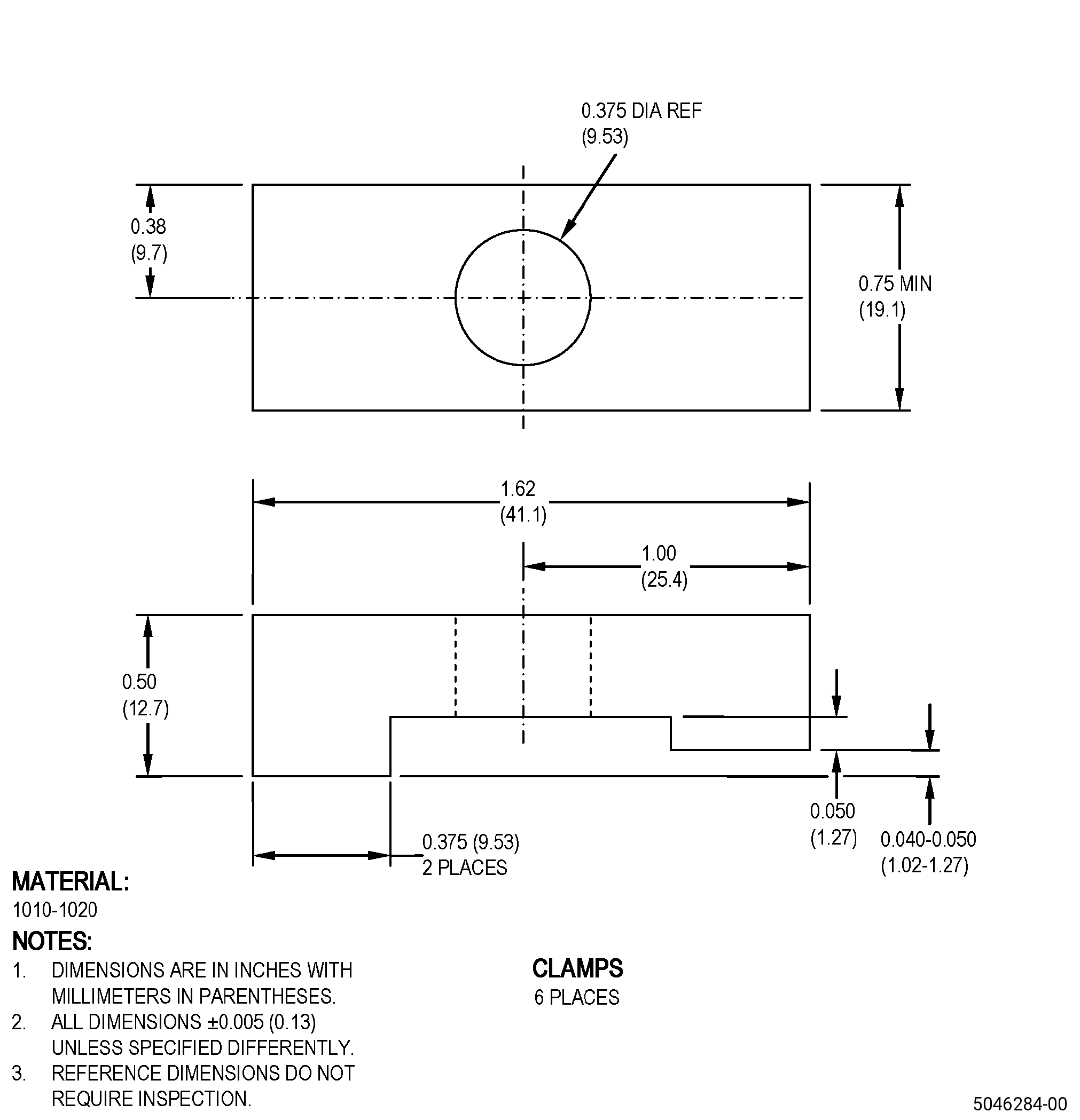
| (3) | Locally Manufactured Tools. |
|
| B. | Consumable Materials. |
|
| C. | Referenced Procedures. |
| D. | Expendable Parts. None. |
| E. | SPD Information. |
|
| (1) | Locally Manufactured SPD. |
|
| F. | Special Solutions. None. |
| G. | Test Specimens. None. |
| 3 . | Dimensional Information. |
| Subtask 72-51-01-220-064 |
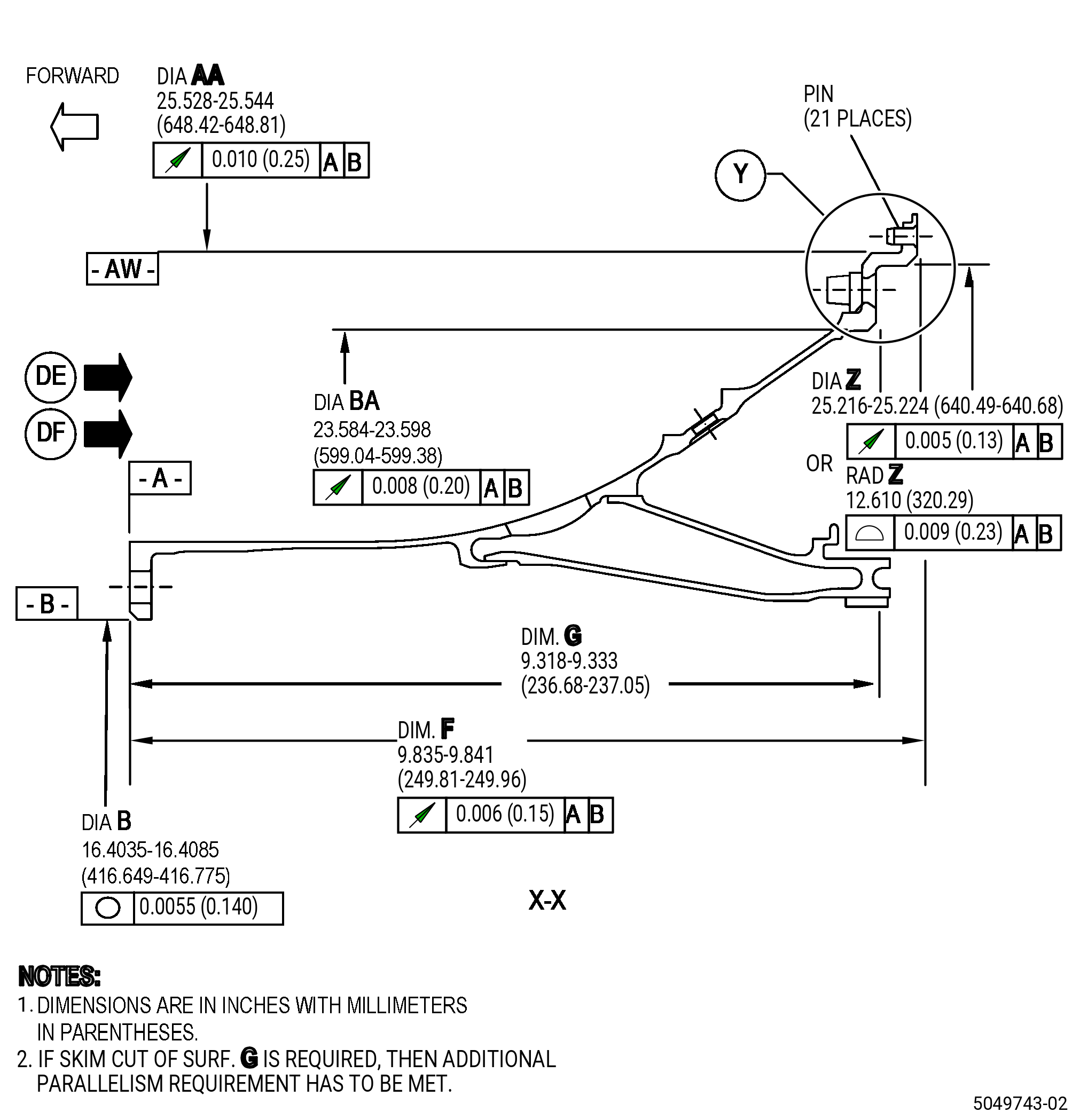
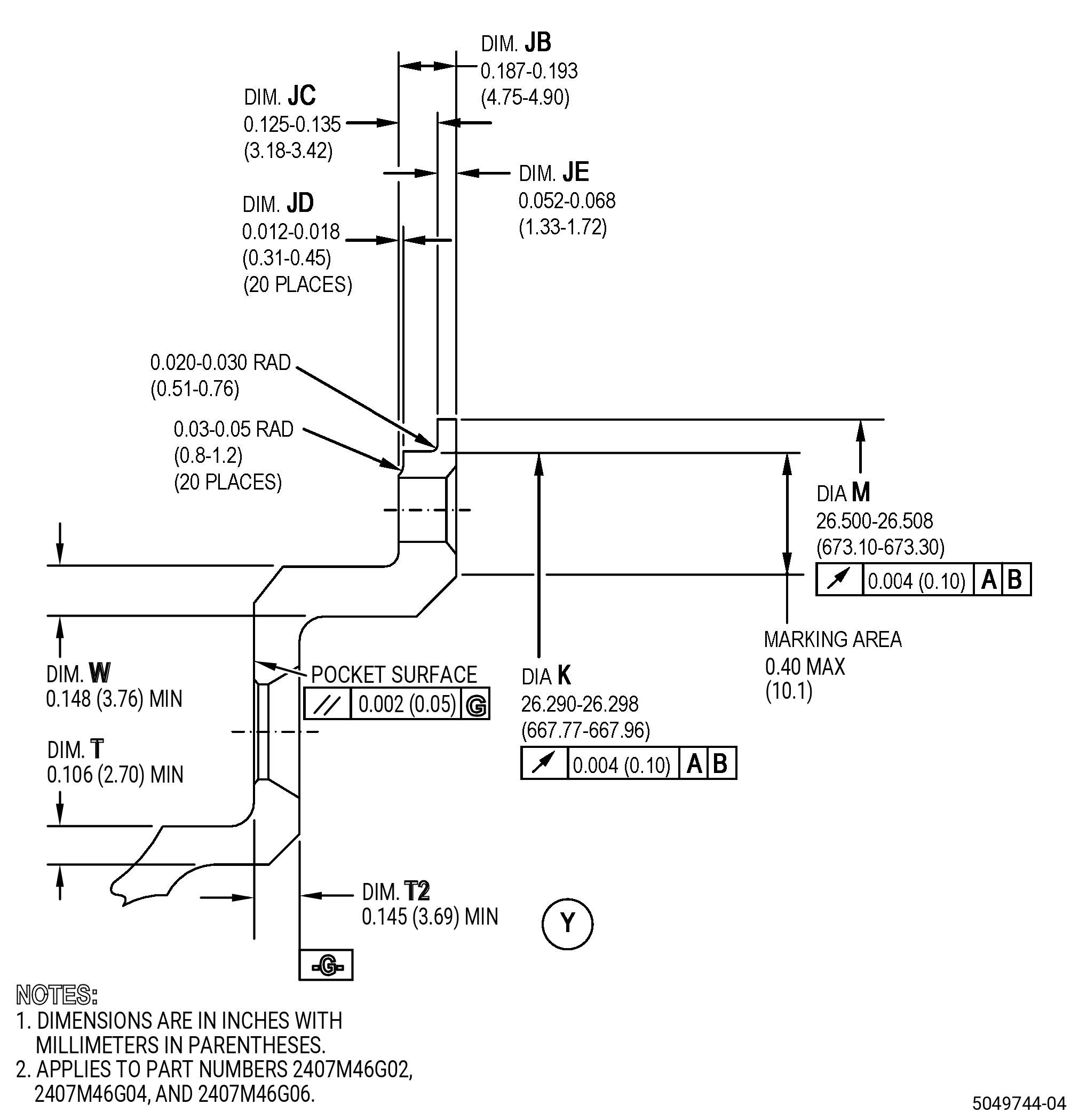
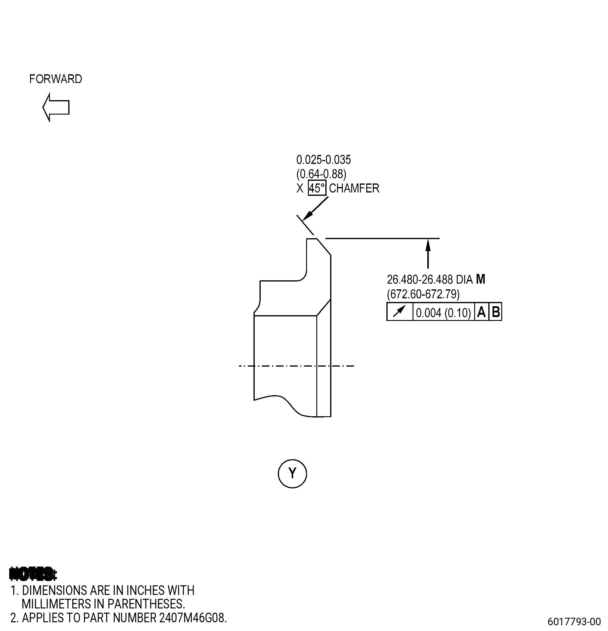
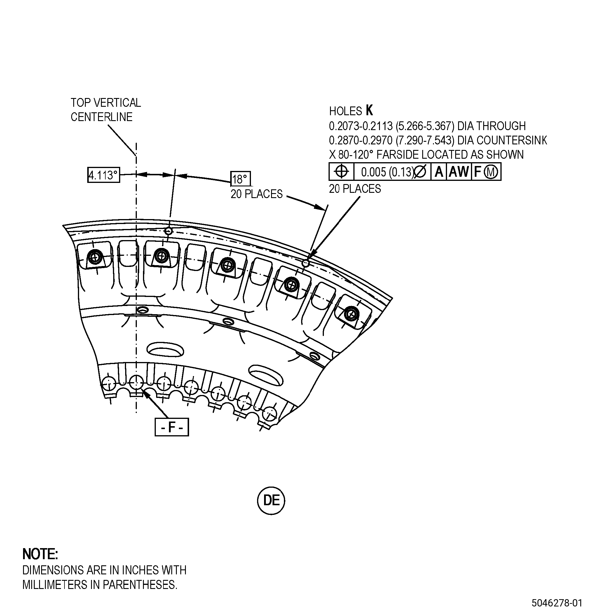
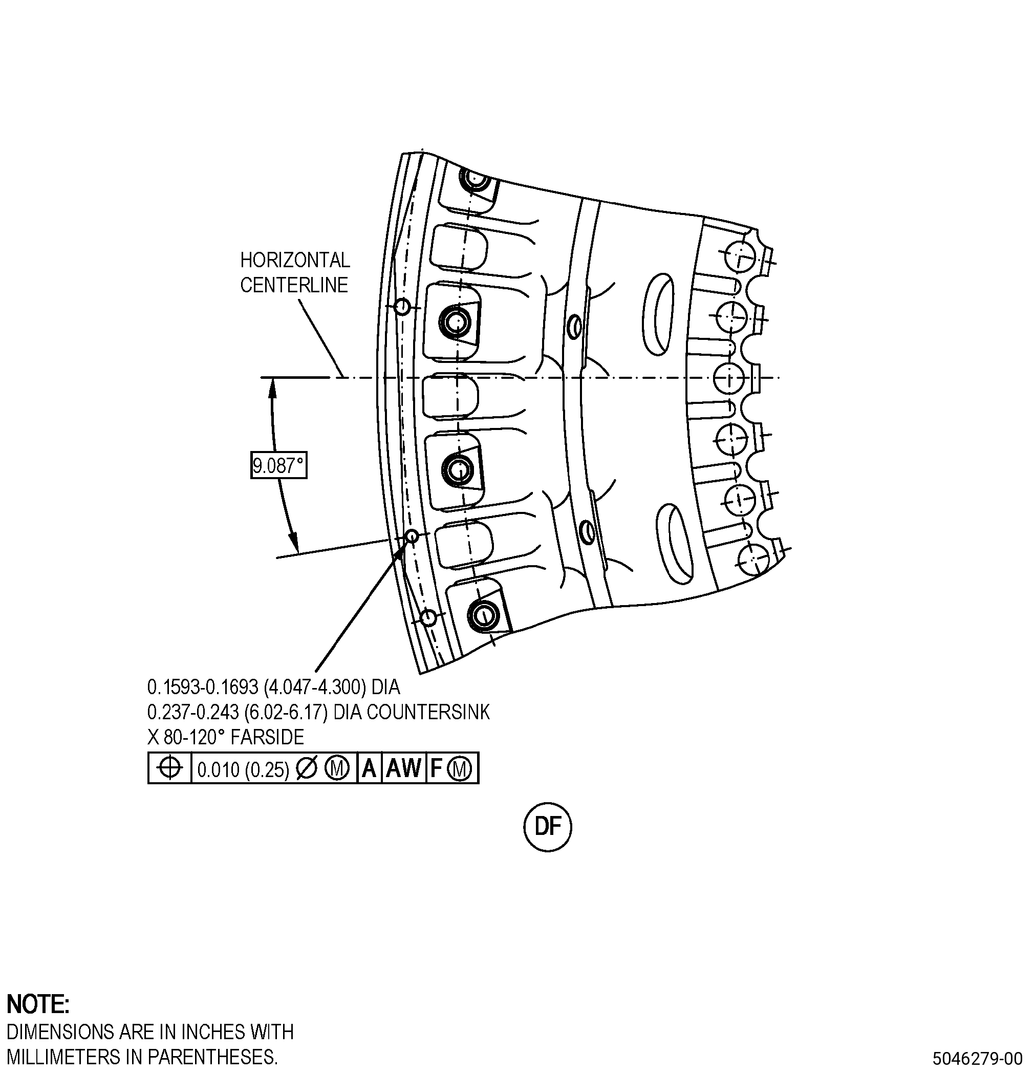
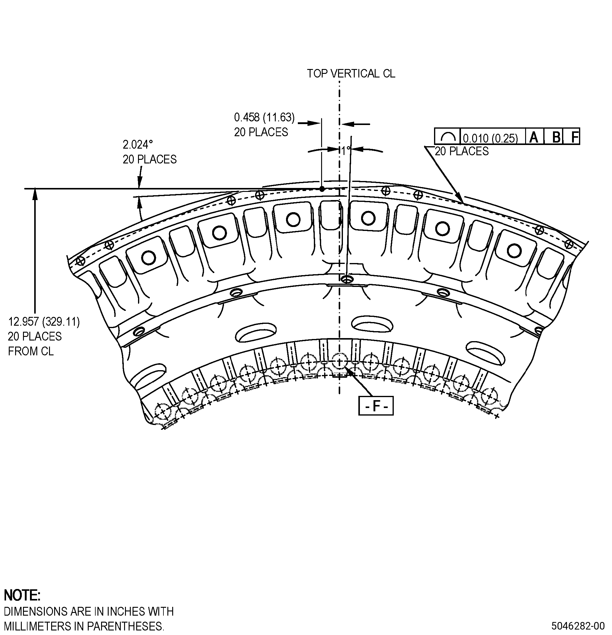
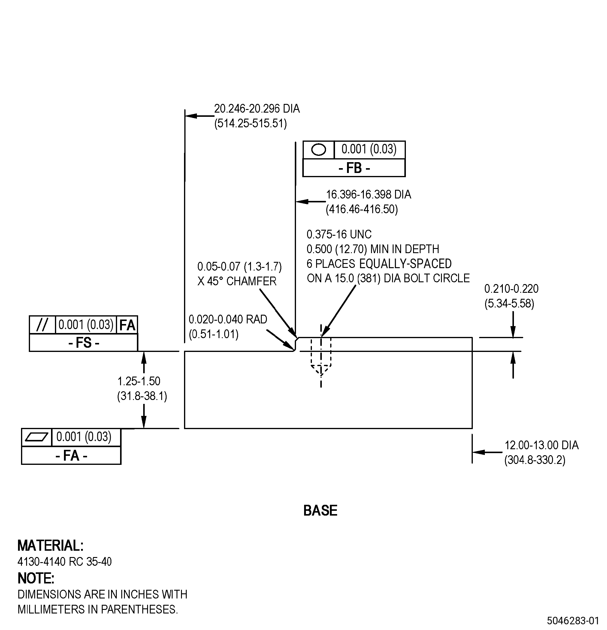
| A. | Refer to Figure 901 and Figure 902 for specified dimensions and locations. |
| NOTE: |
|
| NOTE: |
|
| NOTE: |
|
| NOTE: |
|
| NOTE: |
|
|
| 4 . | Setup Information. |
| Subtask 72-51-01-350-032 |
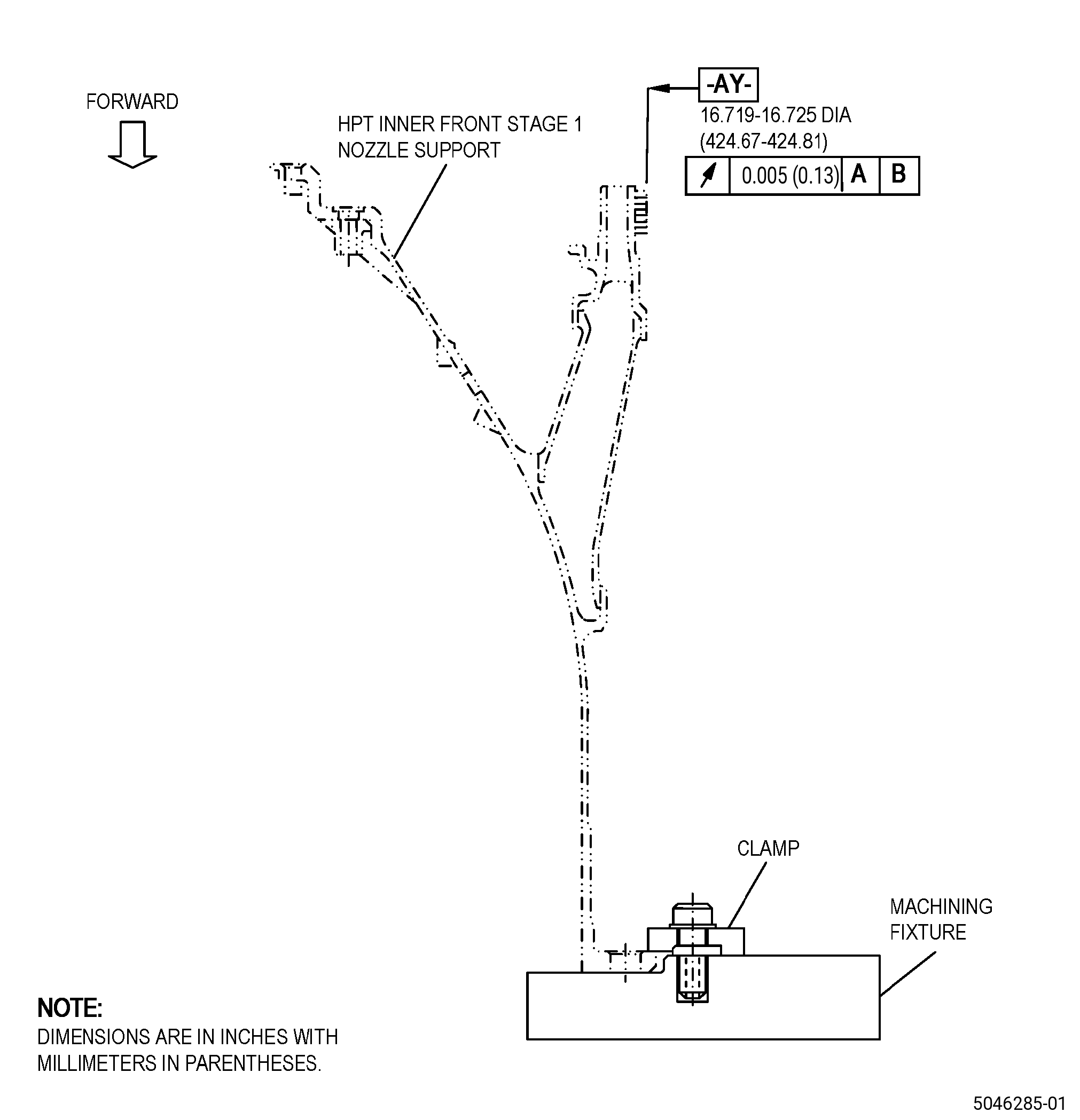
| A. | Set-up the nozzle support for machining. Refer to Figure 903, Figure 904, and as follows: |
| (1) | If necessary, make the machining fixture. |
| (2) | Put the machining fixture on a clean machining table or an equivalent clean and flat surface. |
| (3) | Adjust the position of the machining fixture to get surface FA flat to 0.001 inch (0.02 mm) or less as follows: |
| (a) | If necessary, put C10-155 shims between surface FA of the machining fixture and the surface of the machining table to get surface FA of the machining fixture flat to 0.001 inch (0.02 mm) FIR or less. |
| (b) | Make sure that the runout of surface FS is 0.001 inch (0.02 mm) FIR or less. |
| (4) | Adjust the position of the machining fixture to get surface FB concentric to the machining table axis to 0.002 inch (0.05 mm) or less. |
| (5) | Attach the machining fixture to the machining table with clamps as follows: |
| (a) | Engage the clamps to attach the machining fixture to the machining table. |
| (6) | Measure the runout of surface FS and the concentricity of surface FB of the machining fixture as follows: |
| (a) | Make sure that the machining fixture agrees with the limits specified in Subtask 72-51-01-350-032 (paragraph 4.A.(3) and paragraph 4.A.(4)). |
| (7) | If necessary, do Subtask 72-51-01-350-032 (paragraph 4.A.(3) thru paragraph 4.A.(6)) again to adjust the machining fixture to the correct position. |
| (8) | Put the nozzle support on the machining fixture. Refer to Figure 901, Figure 904, and as follows: |
| (a) | Put the nozzle support on the machining fixture with surface A (datum A) of the nozzle support down on surface FS of the machining fixture. |
| (9) | Adjust the position of the nozzle support to get surface A flat to 0.002 inch (0.05 mm) or less. Refer to Figure 901, Figure 904, and as follows: |
| (a) | If necessary, put C10-155 shims between surface A (datum A) of the nozzle support and surface FS of the machining fixture. |
| (10) | Adjust the position of the nozzle support to get the diameter of surface B (datum B) to agree with the limits. Refer to Figure 901, Figure 904, and as follows: |
| (a) | If necessary, put C10-155 shims between surface B (datum B) of the nozzle support and surface FB of the machining fixture. |
| (11) | Attach the nozzle support to the machining fixture with a minimum of six clamps that are equally spaced. Refer to Figure 903. |
| Subtask 72-51-01-350-033 |
| B. | Set-up the nozzle support for heat treatment as follows: |
| (1) | Put Hastelloy X shims (shims) on top of a graphite plate as follows: |
| (a) | Put the shims on top of a graphite plate to make sure that the nozzle support will not touch the graphite plate directly during the heat treatment. |
| CAUTION: |
|
| (2) | Put the nozzle support on the shims that are equally spaced on the top surface of the graphite plate. |
| (3) | For the quantity and placement requirements of the load thermocouples, refer to TASK 70-44-03-370-004 (FURNACE HEAT TREATMENT) . |
| 5 . | Procedure. |
| Subtask 72-51-01-110-016 |
| A. | If necessary, clean the nozzle support. Refer to TASK 72-51-01-100-801 (72-51-01, CLEANING 001). |
| Subtask 72-51-01-350-034 |
| B. | Record the nozzle support marking information on the surface of the aft flange as follows: |
| (1) | Make sure to record the marking the same as it is. |
| Subtask 72-51-01-350-035 |
| C. | Remove the shank nuts from the nozzle support. Refer to TASK 72-51-01-300-801 (72-51-01, REPAIR 001). |
| Subtask 72-51-01-350-119 |
| D. | For part numbers 2407M46G06 and 2407M46G08 , remove the hard coating from the nozzle support. Refer to TASK 72-51-01-300-810 (72-51-01, REPAIR 011). |
| Subtask 72-51-01-370-012 |
| E. | Optional Procedure. Alternative Procedure Available. If necessary heat-treat the nozzle support. Refer to TASK 70-44-00-800-010 (HEAT TREATING), TASK 70-44-03-370-004 (FURNACE HEAT TREATMENT) , and as follows: |
| (1) | Set-up the nozzle support for heat treatment. Refer to Subtask 72-51-01-350-033 (paragraph 4.B.). |
| (2) | Do a solution heat treatment of the nozzle support as follows: |
| (a) | Use a vacuum of 1.0 micron of mercury or less. |
| (b) | Increase the temperature of the nozzle support to a temperature range of 1835 to 1885°F (1002 to 1029°C) and keep the temperature for 20-30 minutes. |
| (c) | Decrease the temperature of the nozzle support to 1000°F (538°C) in less than 30 minutes. |
| Subtask 72-51-01-370-013 |
| E.A. | Optional Procedure. Alternative Procedure. Heat-treat the nozzle support. Refer to TASK 70-44-00-800-010 (HEAT TREATING), TASK 70-44-03-370-004 (FURNACE HEAT TREATMENT) , and as follows: |
| (1) | Set-up the nozzle support for heat treatment. Refer to Subtask 72-51-01-350-033 (paragraph 4.B.). |
| (2) | Do a solution heat treatment of the nozzle support as follows: |
| (a) | Use a vacuum of 1.0 micron of mercury or less. |
| (b) | Increase the temperature of the nozzle support to a range of 1700 to 1750ºF (927 to 954ºC) and as follows: |
| 1 | Keep this temperature for 10-15 minutes or until the vacuum rate gets back to a vacuum pressure of 5.0 X 10⁻⁴ mm Hg or less (6.7 x 10⁻⁴ millibar). |
| (c) | Increase the temperature of the nozzle support to a temperature range of 1875 to 1925ºF (1024 to 1052ºC) at a rate of 20 to 25ºF (11 to 14ºC) for each minute and as follows: |
| 1 | Keep this temperature for a maximum of 3-5 minutes. |
| NOTE: |
|
| CAUTION: |
|
| (d) | Decrease the temperature of the nozzle support to a temperature range of 1750 to 1800ºF (954 to 982ºC) at a minimum rate of 20ºF (11ºC) for each minute and as follows: |
| 1 | Keep this temperature for 10-15 minutes. |
| (e) | Decrease the temperature of the nozzle support to 975 to 1025ºF (524 to 552ºC) in 30 minutes or less. |
| NOTE: |
|
| (f) | Remove the nozzle support from the furnace. |
| Subtask 72-51-01-320-007 |
| F. | Optional Procedure. Remove the 21 pins from the nozzle support outer flange. Refer to TASK 70-00-03-800-004 (MACHINING DATA), Figure 901, and Figure 902. |
| NOTE: |
|
| Subtask 72-51-01-320-008 |
| G. | Alternative Procedure Available. Machine the cracked area of the nozzle support to the in-process dimension. Refer to TASK 70-00-03-800-004 (MACHINING DATA), Subtask 72-51-01-220-064 (paragraph 3.A.), Figure 901, Figure 902, and as follows: |
| (1) | Set-up the nozzle support for machining. Refer to Subtask 72-51-01-350-032 (paragraph 4.A.). |
| (2) | Machine the outer flange diameter. |
| (3) | If cracks are more than the minimum in-process dimension (diameter M), you can prepare them for welding with a manual blending/grinding process. Refer to TASK 70-41-00-310-001 (WELDING AND BRAZING PRACTICES). |
| (4) | If necessary, machine pin holes to remove remaining wall thickness between machined outer flange diameter and pin hole to prepare them for welding process. |
| Subtask 72-51-01-350-036 |
| (5) | Blend the nozzle support to break all sharp edges on the machined surfaces to 0.005-0.015 inch (0.13-0.38 mm). Refer to TASK 70-42-00-350-002 (BLENDING AND REMOVAL OF HIGH METAL PROCEDURES). |
| Subtask 72-51-01-220-065 |
| (6) | Do an inspection for smooth transition from non-machined surface to machined surface. |
| Subtask 72-51-01-350-037 |
| (7) | Remove the nozzle support from the machining fixture. |
| Subtask 72-51-01-350-038 |
| G.A. | Alternative Procedure. For low number of cracks, blend to remove cracks in the outer flange diameter to prepare them for welding process. Refer to TASK 70-42-00-350-002 (BLENDING AND REMOVAL OF HIGH METAL PROCEDURES) and as follows: |
| (1) | If cracks are more than the minimum in-process dimension (diameter M), you can prepare them for welding. |
| Subtask 72-51-01-110-017 |
| CAUTION: |
|
| H. | Optional Procedure. Clean the nozzle support repair area. Refer to TASK 70-21-00-110-051 (CHEMICAL CLEANING), TASK 70-21-04-120-001 (CLEANING METHOD NO. 4 - DRY ABRASIVE BLAST CLEANING), and as follows. |
| (1) | Apply masking to the honeycomb and inducer passages. |
| (2) | Do the abrasive blast cleaning to the nozzle support with C04-113 220 mesh abrasive compound. |
| Subtask 72-51-01-110-018 |
| I. | Clean the nozzle support. Refer to TASK 72-51-01-100-801 (72-51-01, CLEANING 001). |
| Subtask 72-51-01-110-019 |
| J. | Etch the nozzle support machined areas. Refer to TASK 70-24-00-110-033 (ETCHING PROCEDURES FOR FLUORESCENT-PENETRANT INSPECTION), TASK 70-24-01-110-034 (SWAB ETCHING PROCEDURE), and as follows: |
| (1) | Use Class C etchant. |
| Subtask 72-51-01-230-007 |
| K. | Alternative Procedure Available. Do an inspection of the nozzle support repair area. Refer to TASK 70-32-00-200-002 (INDIRECT INSPECTION METHODS), TASK 70-32-03-230-002 (SPOT-FLUORESCENT-PENETRANT INSPECTION), and as follows: |
| (1) | Use Class A penetrant. |
| (2) | Indications 0.030 inch (0.76 mm) or less are not interpretable and are permitted. |
| (3) | Non-linear indications 0.060 inch (1.52 mm) or less with a minimum distance of 0.15 inch (3.9 mm) between indications are permitted. |
| (4) | Linear indications more than 0.030 inch (0.76 mm) are not permitted. |
| NOTE: |
|
| (5) | Through indications are not permitted. |
| (6) | Microshrinkage must agree with GEAE Photo Standard 8311253, Class 30. |
| Subtask 72-51-01-230-008 |
| K.A. | Alternative Procedure. Do an inspection of the nozzle support repair area. Refer to TASK 70-32-00-200-002 (INDIRECT INSPECTION METHODS), TASK 70-32-02-230-001 (FLUORESCENT PENETRANT INSPECTION), and as follows: |
| (1) | Use Class A penetrant. |
| (2) | Indications 0.030 inch (0.76 mm) or less are not interpretable and are permitted. |
| (3) | Non-linear indications 0.060 inch (1.52 mm) or less with a minimum distance of 0.15 inch (3.9 mm) between indications are permitted. |
| (4) | Linear indications more than 0.030 inch (0.76 mm) are not permitted. |
| NOTE: |
|
| (5) | Through indications are not permitted. |
| (6) | Microshrinkage must agree with GEAE Photo Standard 8311253, Class 30. |
| Subtask 72-51-01-310-005 |
| L. | If you removed the pin hole wall in Subtask 72-51-01-320-008 (paragraph 5.G.(4)), weld the nozzle support to close remaining pin holes. Refer to TASK 70-41-00-310-001 (WELDING AND BRAZING PRACTICES) and as follows: |
| (1) | Use C06-037 GTD 222 weld wire. |
| (2) | Blend the nozzle support to remove unwanted weld material from the outer flange. Refer to TASK 70-42-00-350-002 (BLENDING AND REMOVAL OF HIGH METAL PROCEDURES). |
| Subtask 72-51-01-310-006 |
| M. | Weld the nozzle support outer flange. Refer to TASK 70-41-00-310-001 (WELDING AND BRAZING PRACTICES) and as follows: |
| (1) | Use C06-037 GTD 222 weld wire. |
| Subtask 72-51-01-320-009 |
| N. | Optional Procedure. Machine the nozzle support to the finish dimensions. Refer to TASK 70-00-03-800-004 (MACHINING DATA), Figure 901, Figure 902, and as follows: |
| (1) | Set-up the nozzle support for machining. Refer to Subtask 72-51-01-350-032 (paragraph 4.A.). |
| (2) | Machine the outer flange to the initial contour and as follows: |
| (a) | The transition between welded and non-welded areas must be flush to a maximum of 0.002 inch (0.05 mm). |
| (b) | For part number 2407M46G08 , machine the outer flange chamfer. Refer to Figure 902. |
| Subtask 72-51-01-350-039 |
| (3) | Blend the nozzle support to break all sharp edges on the machined surfaces to 0.005-0.015 inch (0.13-0.38 mm). Refer to TASK 70-42-00-350-002 (BLENDING AND REMOVAL OF HIGH METAL PROCEDURES). |
| (4) | If necessary, open the 21 new pin holes again and one offset. Refer to Figure 902. |
| (5) | Remove the nozzle support from the machining fixture. |
| Subtask 72-51-01-110-020 |
| O. | If you machined the nozzle support, clean it. Refer to TASK 72-51-01-100-801 (72-51-01, CLEANING 001). |
| Subtask 72-51-01-110-021 |
| P. | If you machined the nozzle support, etch it. Refer to TASK 70-24-00-110-033 (ETCHING PROCEDURES FOR FLUORESCENT-PENETRANT INSPECTION), TASK 70-24-01-110-034 (SWAB ETCHING PROCEDURE), and as follows: |
| (1) | Use Class C etchant. |
| Subtask 72-51-01-230-009 |
| Q. | Alternative Procedure Available. Do an inspection of the nozzle support repair area. Refer to TASK 70-32-00-200-002 (INDIRECT INSPECTION METHODS), TASK 70-32-03-230-002 (SPOT-FLUORESCENT-PENETRANT INSPECTION), and as follows: |
| (1) | Use Class A penetrant. |
| (2) | Indications 0.030 inch (0.76 mm) or less are not interpretable and are permitted. |
| (3) | Non-linear indications 0.060 inch (1.52 mm) or less with a minimum distance of 0.15 inch (3.9 mm) between indications are permitted. |
| (4) | Linear indications more than 0.030 inch (0.76 mm) are not permitted. |
| NOTE: |
|
| (5) | Through indications are not permitted. |
| (6) | Microshrinkage must agree with GEAE Photo Standard 8311253, Class 30. |
| Subtask 72-51-01-230-010 |
| Q.A. | Alternative Procedure. Do an inspection of the nozzle support repair area. Refer to TASK 70-32-00-200-002 (INDIRECT INSPECTION METHODS), TASK 70-32-02-230-001 (FLUORESCENT PENETRANT INSPECTION), and as follows: |
| (1) | Use Class A penetrant. |
| (2) | Indications 0.030 inch (0.76 mm) or less are not interpretable and are permitted. |
| (3) | Non-linear indications 0.060 inch (1.52 mm) or less with a minimum distance of 0.15 inch (3.9 mm) between indications are permitted. |
| (4) | Linear indications more than 0.030 inch (0.76 mm) are not permitted. |
| NOTE: |
|
| (5) | Through indications are not permitted. |
| (6) | Microshrinkage must agree with GEAE Photo Standard 8311253, Class 30. |
| Subtask 72-51-01-260-001 |
| R. | Do an inspection of the nozzle support in the weld repaired area only. Refer to TASK 70-32-00-200-002 (INDIRECT INSPECTION METHODS), TASK 70-32-05-260-001 (RADIOGRAPHIC INSPECTION), and as follows: |
| (1) | Indications 0.030 inch (0.76 mm) or less are not interpretable and are permitted. |
| (2) | Non-linear indications 0.060 inch (1.52 mm) or less with a minimum distance of 0.15 inch (3.9 mm) between indications are permitted. |
| (3) | Linear indications more than 0.030 inch (0.76 mm) are not permitted. |
| (4) | Deleted. |
| (5) | Deleted. |
| NOTE: |
|
| Subtask 72-51-01-350-040 |
| S. | If necessary, do Subtask 72-51-01-310-006 (paragraph 5.L.) thru Subtask 72-51-01-260-001 (paragraph 5.Q.), again until you remove all the rejected indications from the nozzle support repair area. |
| Subtask 72-51-01-110-022 |
| T. | If necessary, clean the nozzle support. Refer to TASK 72-51-01-100-801 (72-51-01, CLEANING 001). |
| Subtask 72-51-01-370-007 |
| U. | Alternative Procedure Available. Heat-treat the nozzle support. Refer to TASK 70-44-00-800-010 (HEAT TREATING), TASK 70-44-03-370-004 (FURNACE HEAT TREATMENT), and as follows: |
| (1) | Set-up the nozzle support for heat treatment. Refer to Subtask 72-51-01-350-033 (paragraph 4.B.). |
| (2) | Do a solution heat treatment of the nozzle support as follows: |
| (a) | Use a vacuum of 1.0 micron of mercury or less. |
| (b) | Increase the temperature of the nozzle support to a temperature range of 1835 to 1885°F (1002 to 1029°C) and keep the temperature for 20-30 minutes. |
| (c) | Decrease the temperature of the nozzle support to 1000°F (538°C) in less than 30 minutes. |
| Subtask 72-51-01-370-008 |
| U.A. | Alternative Procedure. Heat-treat the nozzle support. Refer to TASK 70-44-00-800-010 (HEAT TREATING), TASK 70-44-03-370-004 (FURNACE HEAT TREATMENT) , and as follows: |
| (1) | Set-up the nozzle support for heat treatment. Refer to Subtask 72-51-01-350-033 (paragraph 4.B.). |
| (2) | Do a solution heat treatment of the nozzle support as follows: |
| (a) | Use a vacuum of 1.0 micron of mercury or less. |
| (b) | Increase the temperature of the nozzle support to a range of 1700 to 1750ºF (927 to 954ºC) and as follows: |
| 1 | Keep this temperature for 10-15 minutes or until the vacuum rate gets back to a vacuum pressure of 5.0 X 10⁻⁴ mm Hg or less (6.7x10⁻⁴ millibar). |
| (c) | Increase the temperature of the nozzle support to a temperature range of 1875 to 1925ºF (1024 to 1052ºC) at a rate of 20 to 25ºF (11 to 14ºC) for each minute and as follows: |
| 1 | Keep this temperature for a maximum of 3-5 minutes. |
| NOTE: |
|
| CAUTION: |
|
| (d) | Decrease the temperature of the nozzle support to a temperature range of 1750 to 1800ºF (954 to 982ºC) at a minimum rate of 20ºF (11ºC) for each minute and as follows: |
| 1 | Keep this temperature for 10-15 minutes. |
| (e) | Decrease the temperature of the nozzle support to 975 to 1025ºF (524 to 552ºC) in 30 minutes or less. |
| NOTE: |
|
| (f) | Remove the nozzle support from the furnace. |
| Subtask 72-51-01-370-009 |
| V. | Heat-treat the nozzle support. Refer to TASK 70-44-00-800-010 (HEAT TREATING), TASK 70-44-03-370-004 (FURNACE HEAT TREATMENT), and as follows: |
| (1) | Set-up the nozzle support for heat treatment. Refer to Subtask 72-51-01-350-033 (paragraph 4.B.). |
| (2) | Do an age heat treatment to the nozzle support as follows: |
| (a) | Heat-treat the nozzle support at 1450 to 1500°F (788 to 816°C) for 8 hours. |
| (b) | Decrease the temperature of the nozzle support to 1000°F (538°C) at a rate not less than 25°F (14°C) per minute. |
| (c) | Decrease the nozzle support temperature to room temperature. |
| (d) | Remove the nozzle support from the furnace. |
| Subtask 72-51-01-310-007 |
| W. | Do a visual inspection in the nozzle support brazed areas. Refer to TASK 70-41-00-310-001 (WELDING AND BRAZING PRACTICES), TASK 70-41-03-310-004 (HIGH TEMPERATURE FURNACE BRAZE), and as follows: |
| (1) | The diameter or length of one void and non-bonded areas must not be more than the 0.08 inch (2.0 mm). |
| (2) | There must not be more than three voids or non-bonded areas in a section with a length of 1.0 inch (25 mm) of braze bond area. |
| (3) | Irregular surface porosity is permitted. Indications 0.015 inch (0.38 mm) or less are not interpretable. |
| (4) | Through voids are not permitted. |
| Subtask 72-51-01-220-066 |
| X. | Alternative Procedure Available. Do an inspection of the honeycomb. Refer to TASK 70-33-00-999-001 (SPECIAL INSPECTION PROCEDURES), TASK 70-33-02-220-005 (CAPILLARY INSPECTION OF OPEN FACE HONEYCOMB STRUCTURES), and as follows: |
| (1) | You must fully bond the honeycomb core to its backing surface in 80 percent of the total contact area. |
| (2) | Unbonded areas cannot contain more than 10 totally unbonded adjacent cells circumferentially by five totally unbonded adjacent cells axially. |
| (3) | Honeycomb core node bond is not interpretable. |
| (4) | Unbonded areas must be separated by a minimum of five adjacent bonded cells. |
| (5) | An unbonded area cannot include open cells, partial cells, or splices. |
| Subtask 72-51-01-220-067 |
| X.A. | Alternative Procedure. Do an inspection of the honeycomb with a video microscope under a minimum of 10X magnification. Refer to Subtask 72-51-01-310-007 (paragraph 5.W.(1) thru paragraph 5.W.(4)) for the inspection limits. |
| Subtask 72-51-01-350-041 |
| Y. | If you did not machine the nozzle support per Subtask 72-51-01-320-009 (paragraph 5.N), machine the nozzle support to the finish dimensions. Refer to TASK 70-00-03-800-004 (MACHINING DATA), Figure 901, Figure 902, and as follows: |
| (1) | Set-up the nozzle support for machining. Refer to Subtask 72-51-01-350-032 (paragraph 4.A.). |
| (2) | Machine the outer flange to the initial contour and as follows: |
| (a) | The transition between welded and non-welded areas must be flush to a maximum of 0.002 inch (0.05 mm). |
| (b) | For part number 2407M46G08 , machine the outer flange chamfer. Refer to Figure 902. |
| Subtask 72-51-01-350-042 |
| (3) | Blend the nozzle support to break all sharp edges on the machined surfaces to 0.005-0.015 inch (0.13-0.38 mm). Refer to TASK 70-42-00-350-002 (BLENDING AND REMOVAL OF HIGH METAL PROCEDURES). |
| Subtask 72-51-01-220-068 |
| (4) | Deleted. |
| Subtask 72-51-01-350-043 |
| (5) | If necessary, open the 21 new pin holes and one offset. Refer to Figure 902. |
| (6) | Remove the nozzle support from the machining fixture. |
| Subtask 72-51-01-320-010 |
| Z. | Optional Procedure. Do a dimensional inspection (runout and dimensions), and if necessary, do a skim cut in diameter AA, diameter BA, diameter Z, and/or surface G to the minimum serviceable limits. Refer to TASK 70-00-03-800-004 (MACHINING DATA), Figure 902, and as follows: |
| (1) | Set-up the nozzle support for machining. Refer to Subtask 72-51-01-350-032 (paragraph 4.A.). |
| (2) | Check the runout and dimensions for diameters AA, BA, and Z. |
| (3) | Check dimension G. |
| (4) | Machine the diameters AA, BA, Z, and surface G as necessary. |
| NOTE: |
|
| NOTE: |
|
| NOTE: |
|
| Subtask 72-51-01-350-062 |
| (5) | Blend the nozzle support to break all sharp edges and have a smooth transition to the inner radius. Refer to TASK 70-42-00-350-002 (BLENDING AND REMOVAL OF HIGH METAL PROCEDURES). |
| Subtask 72-51-01-220-079 |
| (6) | Do an inspection for smooth transition from non-machined surface to machined surface. |
| Subtask 72-51-01-350-063 |
| (7) | Remove the nozzle support from the machining fixture. |
| Subtask 72-51-01-110-023 |
| AA. | If necessary, clean the nozzle support. Refer to TASK 72-51-01-100-801 (72-51-01, CLEANING 001). |
| Subtask 72-51-01-110-024 |
| AB. | If you performed Subtask 72-51-01-350-041 (paragraph 5.Y) and/or Subtask 72-51-01-320-010 (paragraph 5.Z), etch the nozzle support machined areas. Refer to TASK 70-24-00-110-033 (ETCHING PROCEDURES FOR FLUORESCENT-PENETRANT INSPECTION), TASK 70-24-01-110-034 (SWAB ETCHING PROCEDURE), and as follows: |
| (1) | Use Class C etchant. |
| Subtask 72-51-01-230-011 |
| AC. | Do an inspection of the nozzle support. Refer to TASK 70-32-00-200-002 (INDIRECT INSPECTION METHODS), TASK 70-32-02-230-001 (FLUORESCENT PENETRANT INSPECTION), and as follows: |
| (1) | Use Class A penetrant. |
| (2) | Indications 0.030 inch (0.76 mm) or less are not interpretable and are permitted. |
| (3) | Non-linear indications 0.060 inch (1.52 mm) or less with a minimum distance of 0.15 inch (3.9 mm) between indications are permitted. |
| (4) | Linear indications more than 0.030 inch (0.76 mm) are not permitted. |
| NOTE: |
|
| (5) | Through indications are not permitted. |
| (6) | Microshrinkage must agree with GEAE Photo Standard 8311253, Class 30. |
| Subtask 72-51-01-350-044 |
| AD. | If necessary, do Subtask 72-51-01-310-006 (paragraph 5.M.) thru Subtask 72-51-01-230-011 (paragraph 5.AC.) again until you remove all the rejected indications from the nozzle support repair area. |
| Subtask 72-51-01-110-025 |
| AE. | Clean the nozzle support. Refer to TASK 72-51-01-100-801 (72-51-01, CLEANING 001). |
| Subtask 72-51-01-220-069 |
| AF. | Deleted. |
| Subtask 72-51-01-350-045 |
| AG. | Deleted. |
| Subtask 72-51-01-230-012 |
| AH. | Deleted. |
| Subtask 72-51-01-350-046 |
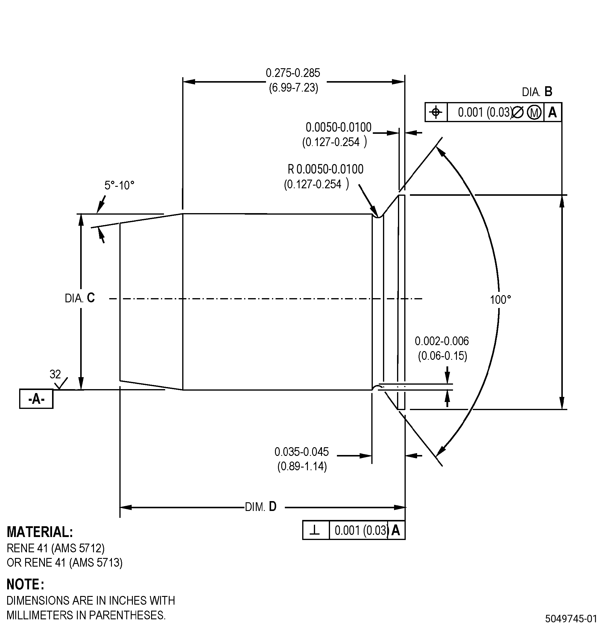
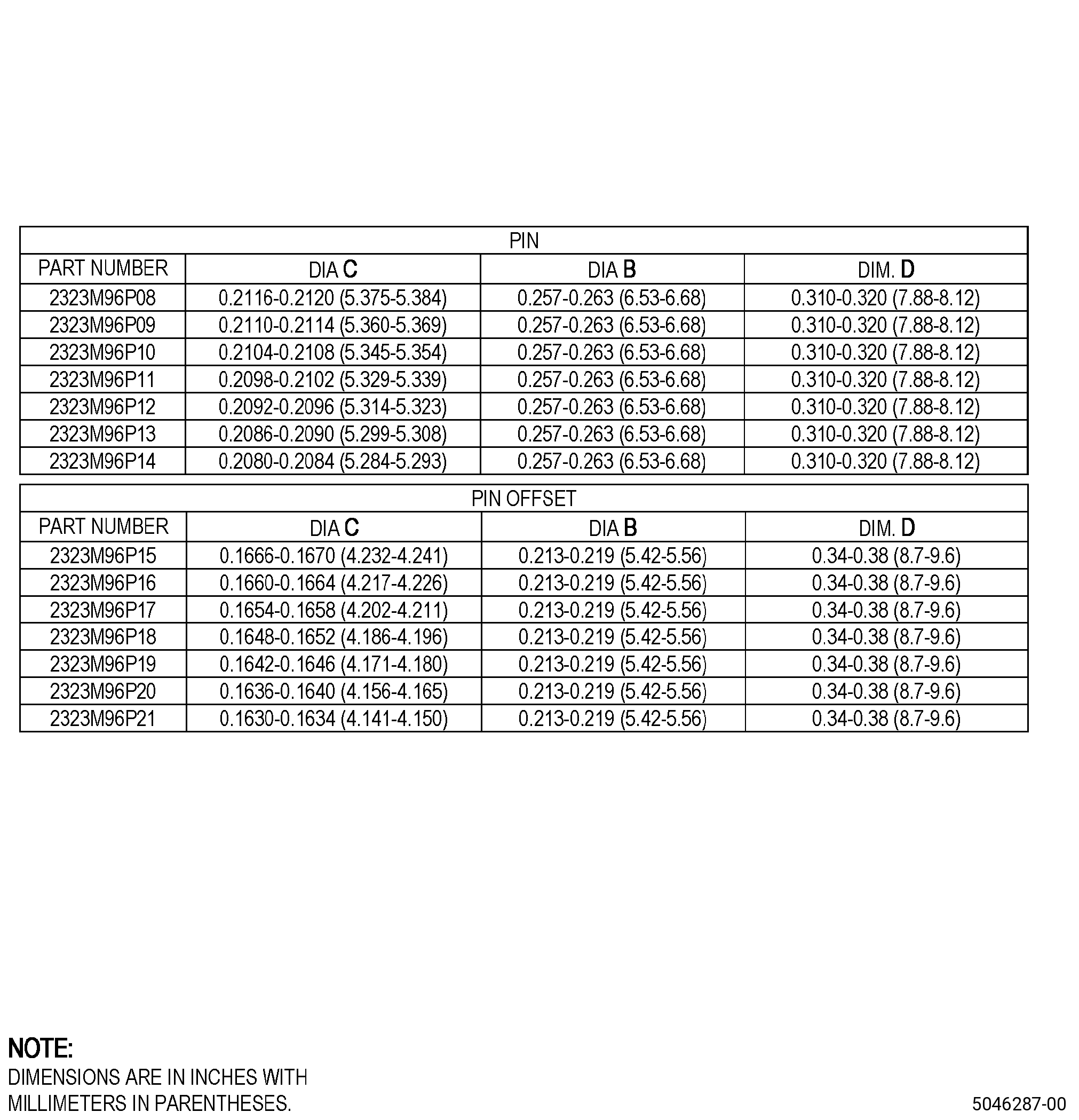
| AI. | If you performed Subtask 72-51-01-370-012 (paragraph 5.E.), install the 21 pins in the nozzle support outer flange. Refer to Figure 901, Figure 902, and as follows: |
| Subtask 72-51-01-350-047 |
| (1) | Alternative Procedure Available. Install the pin you removed in Subtask 72-51-01-370-012 (paragraph 5.E.), if they agree with the requirements specified in Figure 905, and do as follows: |
| Subtask 72-51-01-230-036 |
| (a) | Do an inspection of the pins. Refer to TASK 70-32-00-200-002 (INDIRECT INSPECTION METHODS), TASK 70-32-02-230-001 (FLUORESCENT PENETRANT INSPECTION), and as follows: |
| 1 | Use Class A penetrant. |
| 2 | Indications less than 0.030 inch (0.76 mm) or less are not interpretable and are permitted. |
| 3 | Non-linear indications 0.060 inch (1.52 mm) or less with a minimum distance of 0.50 inch (12.7 mm) between indications are permitted. |
| 4 | Linear indications more than 0.060 inch (1.52 mm) are not permitted. |
| NOTE: |
|
| 5 | Make sure the pin agrees with the necessary interference. |
| 6 | You must assemble the pin into the hole with a dimensional interference fit of 0.0002-0.0011 inch (0.006-0.027 mm). |
| Subtask 72-51-01-350-048 |
| (1).B. | Alternative Procedure. Get the replacement pins. Refer to paragraph 2.E., SPD Information, and as follows: |
| (a) | Make sure the pin agrees with the necessary interference. |
| (b) | You must assemble the pin into the hole with a dimensional interference fit of 0.0002-0.0011 inch (0.006-0.027 mm). |
| Subtask 72-51-01-350-049 |
| (1).C. | Alternative Procedure. Make the replacement pins. Refer to paragraph 2.E.(1), Figure 905 and as follows: |
| (a) | If the pins are made according to AMS 5712, do a heat treatment to ensure mechanical properties. Refer to TASK 70-44-00-800-010 (HEAT TREATING), TASK 70-44-03-370-004 (FURNACE HEAT TREATMENT) , and as follows: |
| 1 | Do a solution heat treatment of the pins as follows: |
| a | Increase the temperature of the pin to a temperature of 1950°F (1066°C) and keep the temperature for 30 minutes. |
| b | Decrease the temperature of the pin to 800°F (427°C). |
| 2 | Do an age heat treatment of the pin as follows: |
| a | Increase the temperature of the pin to a temperature of 1400°F (760°C) and keep the temperature for 16 hours. |
| b | Decrease the temperature of the pin to 800°F (427°C). |
| (b) | Do an inspection of the pins. Refer to TASK 70-32-00-200-002 (INDIRECT INSPECTION METHODS), TASK 70-32-02-230-001 (FLUORESCENT PENETRANT INSPECTION), and as follows: |
| 1 | Use Class A penetrant. |
| 2 | Indications 0.030 inch (0.76 mm) or less are not interpretable and are permitted. |
| 3 | Non-linear indications 0.060 inch (1.52 mm) or less with a minimum distance of 0.50 inch (12.7 mm) between indications are permitted. |
| 4 | Linear indications more than 0.060 inch (1.52 mm) are not permitted. |
| NOTE: |
|
| (c) | Make sure the pin agrees with necessary interference. |
| (d) | You must assemble the pin into the hole with a diametrical interference fit of 0.0002-0.0011 inch (0.006-0.027 mm). |
| Subtask 72-51-01-350-050 |
| (2) | Chill the pin in dry ice to decrease the temperature of the pin for a minimum of 15 minutes. |
| (3) | Put the pin in the hole. |
| (4) | Lightly tap each pin with a plastic rod and mallet until the pins are flush or below the surface of the nozzle support outer flange. |
| (5) | Let the pin get the same temperature as the nozzle support. |
| (6) | Use a criss-cross method. |
| (7) | Do an inspection of the pins in the nozzle support outer flange. Refer to Figure 901, Figure 902, and as follows: |
| (a) | Make sure that the pins are flush or below the surface of the nozzle support outer flange. |
| Subtask 72-51-01-350-120 |
| AJ. | For part numbers 2407M46G06 and 2407M46G08 , apply the hard coating from the nozzle support. Refer to TASK 72-51-01-300-810 (72-51-01, REPAIR 011). |
| Subtask 72-51-01-220-070 |
| AK. | Deleted. |
| Subtask 72-51-01-350-051 |
| AL. | Put a mark again in the nozzle support. Refer to TASK 70-16-00-350-001 (MARKING PRACTICES), TASK 70-16-08-350-001 (DOT PEEN MARKING FOR OPTICAL CHARACTER RECOGNITION), and as follows: |
| (1) | Use the marking information that you recorded in Subtask 72-51-01-350-034 (paragraph 5.B.) as follows: |
| (a) | Make sure to use the same mark that the nozzle support initially had. |
| (2) | Put a mark with the part number, serial number, and manufacturer identification number on the nozzle support marking area. Refer to Figure 902 and as follows: |
| (a) | Use Method 2, OCR-DM3. |
| Subtask 72-51-01-350-052 |
| AM. | Install the shank nuts in the nozzle support. Refer to TASK 72-51-01-300-801 (72-51-01, REPAIR 001). |
| Subtask 72-51-01-220-121 |
| AN. | Do an inspection of the nozzle support. Refer to TASK 72-51-01-200-801 (72-51-01, INSPECTION 001) and Figure 902. |