| GENX-1B CLEANING,INSPECTION,AND REPAIR MANUAL | Dated: 06/01/2021 | |
| CIR 72-51-01 , REPAIR 008 | ||
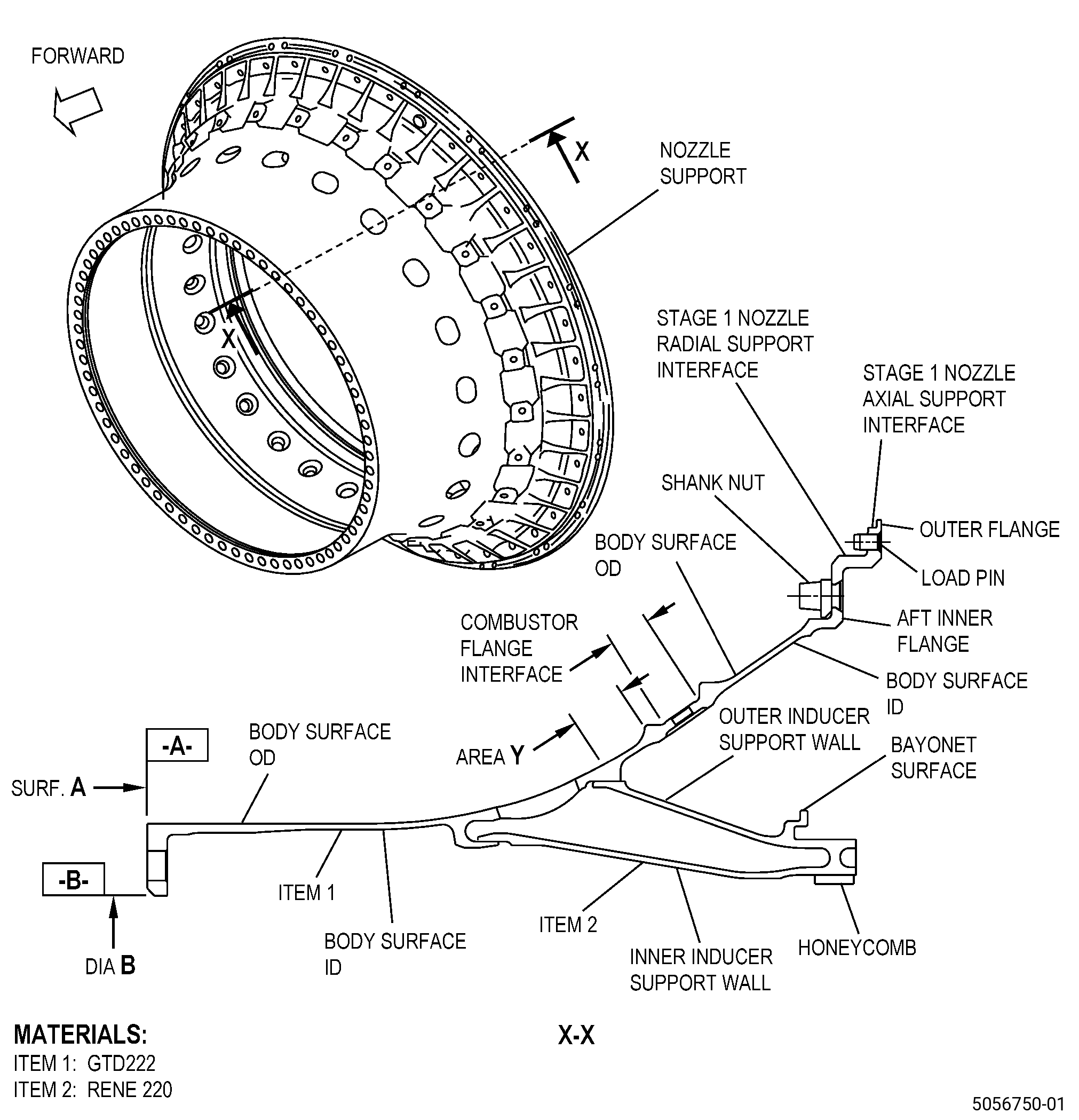
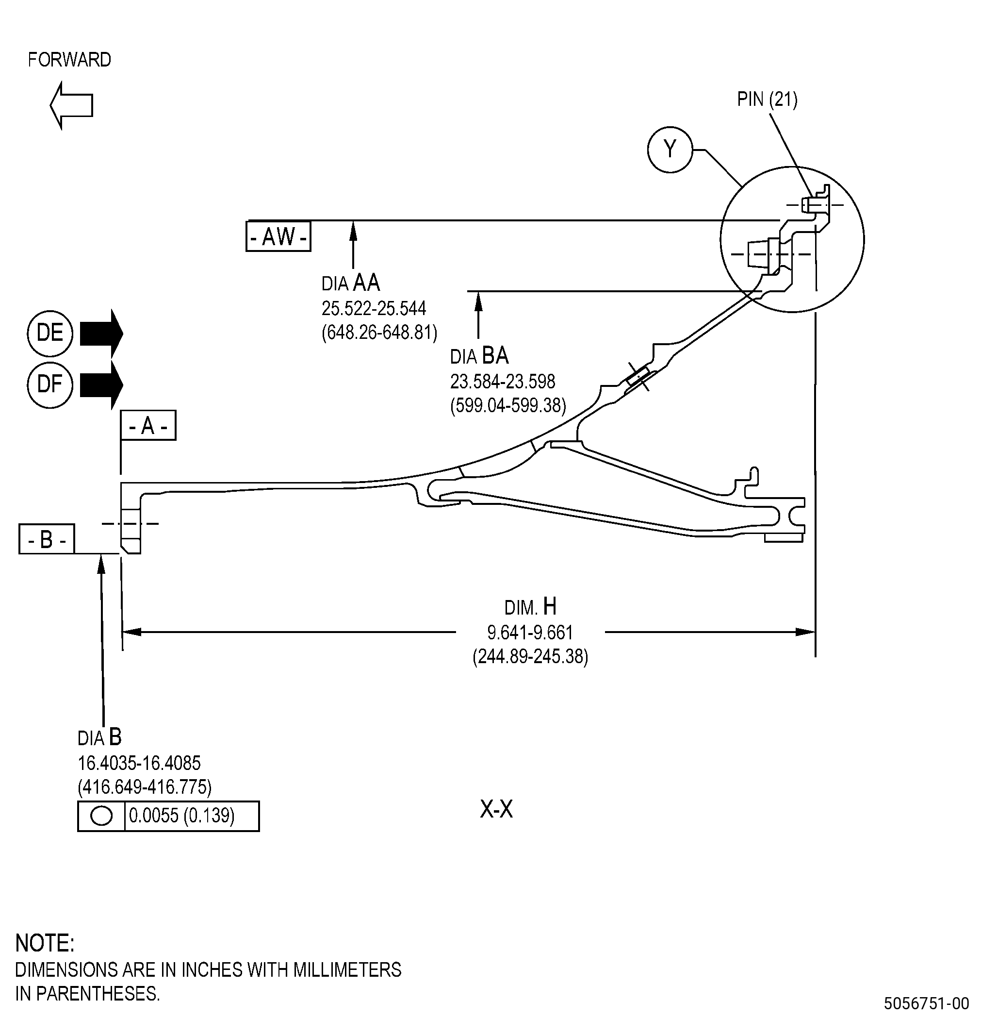
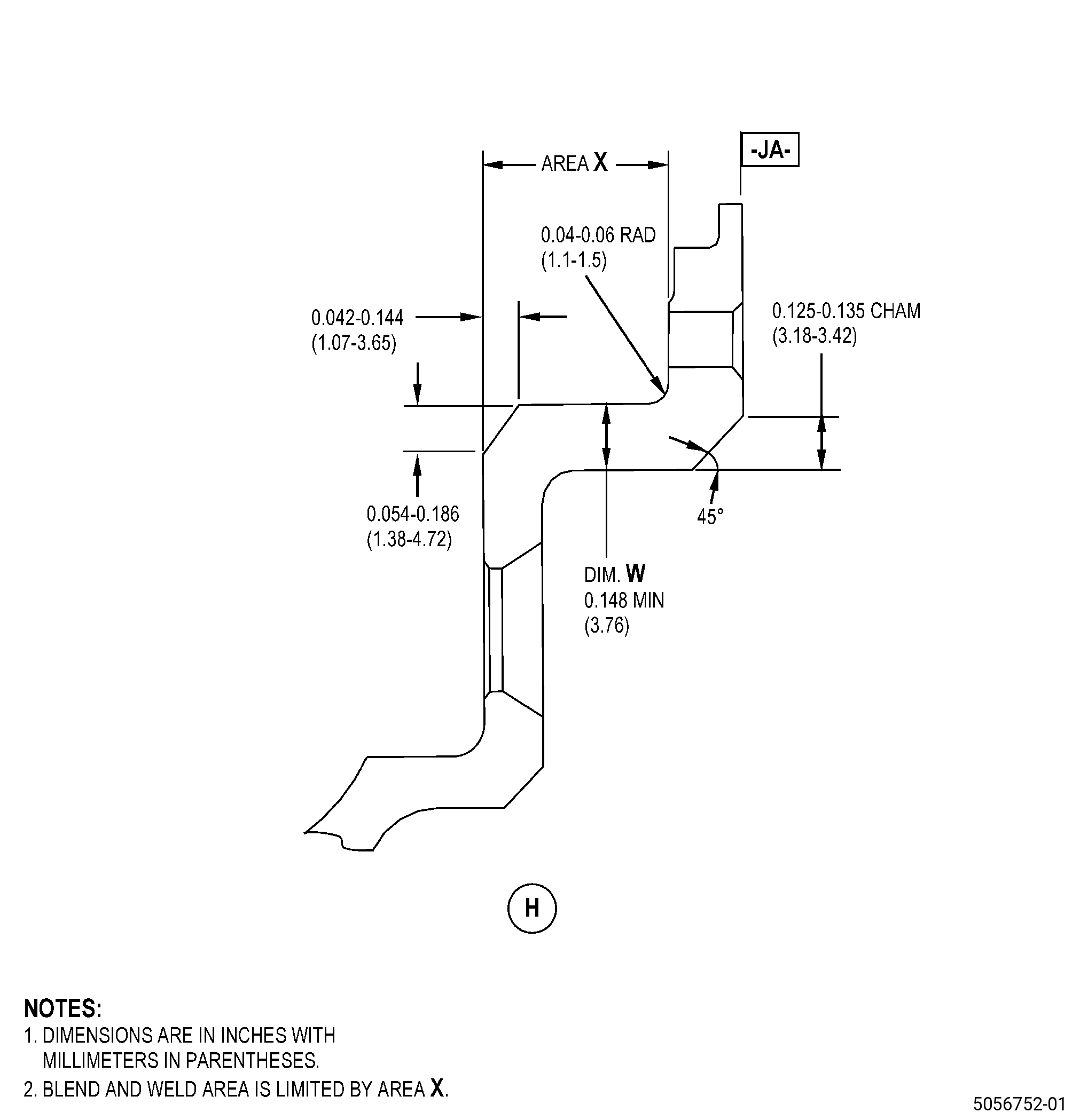
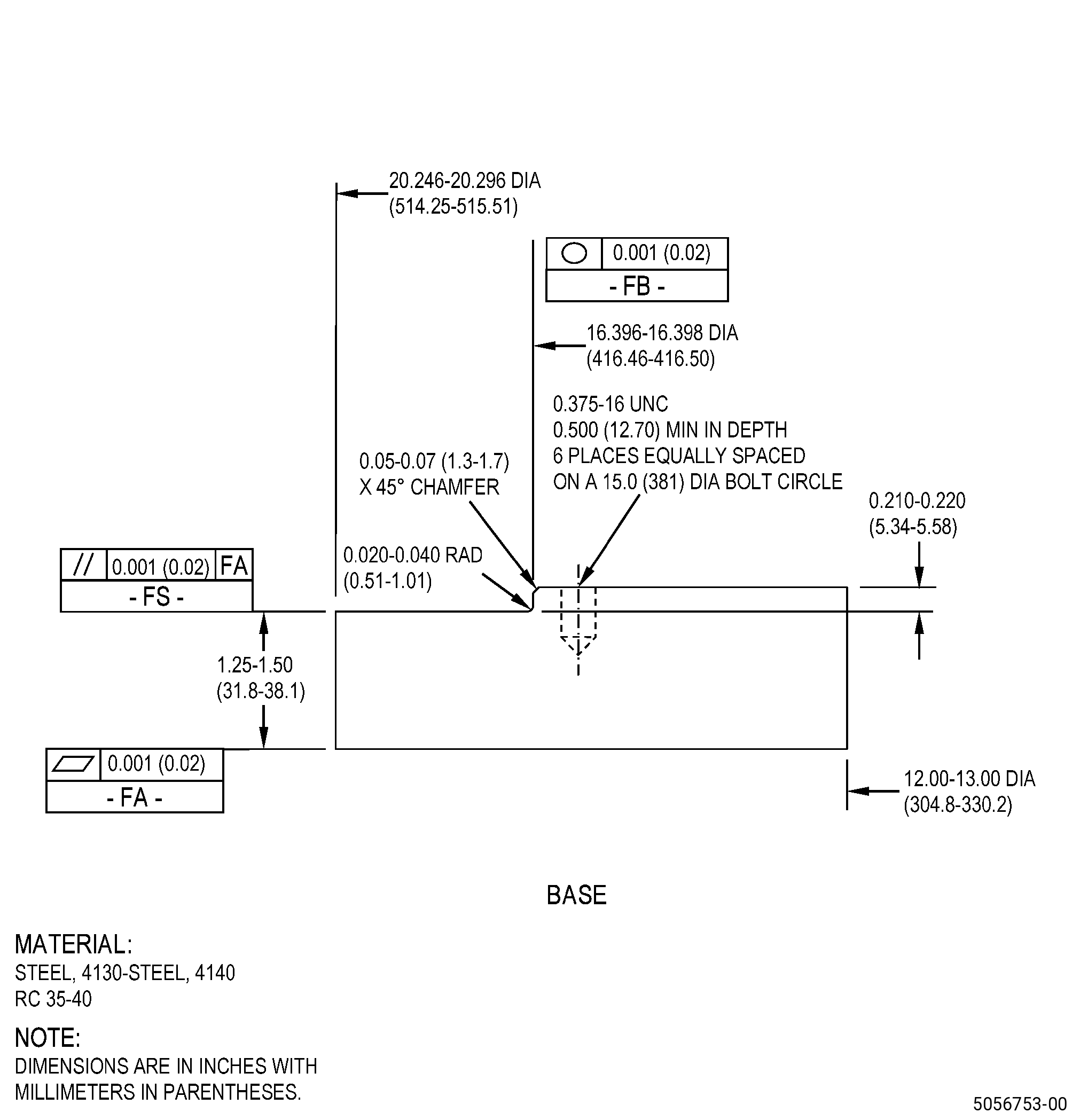
| HIGH PRESSURE TURBINE STAGE 1 NOZZLE SUPPORT - REPAIR - WELD REPAIR OF THE STAGE 1 NOZZLE RADIAL SUPPORT INTERFACE AND/OR BODY SURFACE OUTER AND/OR INNER DIAMETER | ||