| GENX-1B CLEANING,INSPECTION,AND REPAIR MANUAL | Dated: 05/10/2021 | |
| CIR 72-51-01 , REPAIR 014 | ||
| HIGH PRESSURE TURBINE STAGE 1 NOZZLE SUPPORT - REPAIR - THERMAL SPRAY REPAIR OF DIAMETER AA | ||
| GENX-1B CLEANING,INSPECTION,AND REPAIR MANUAL | Dated: 05/10/2021 | |
| CIR 72-51-01 , REPAIR 014 | ||
| HIGH PRESSURE TURBINE STAGE 1 NOZZLE SUPPORT - REPAIR - THERMAL SPRAY REPAIR OF DIAMETER AA | ||
| * * * FOR ALL |
| TASK 72-51-01-300-813 |
| 1 . | Thermal Spray Repair Of Diameter AA. |
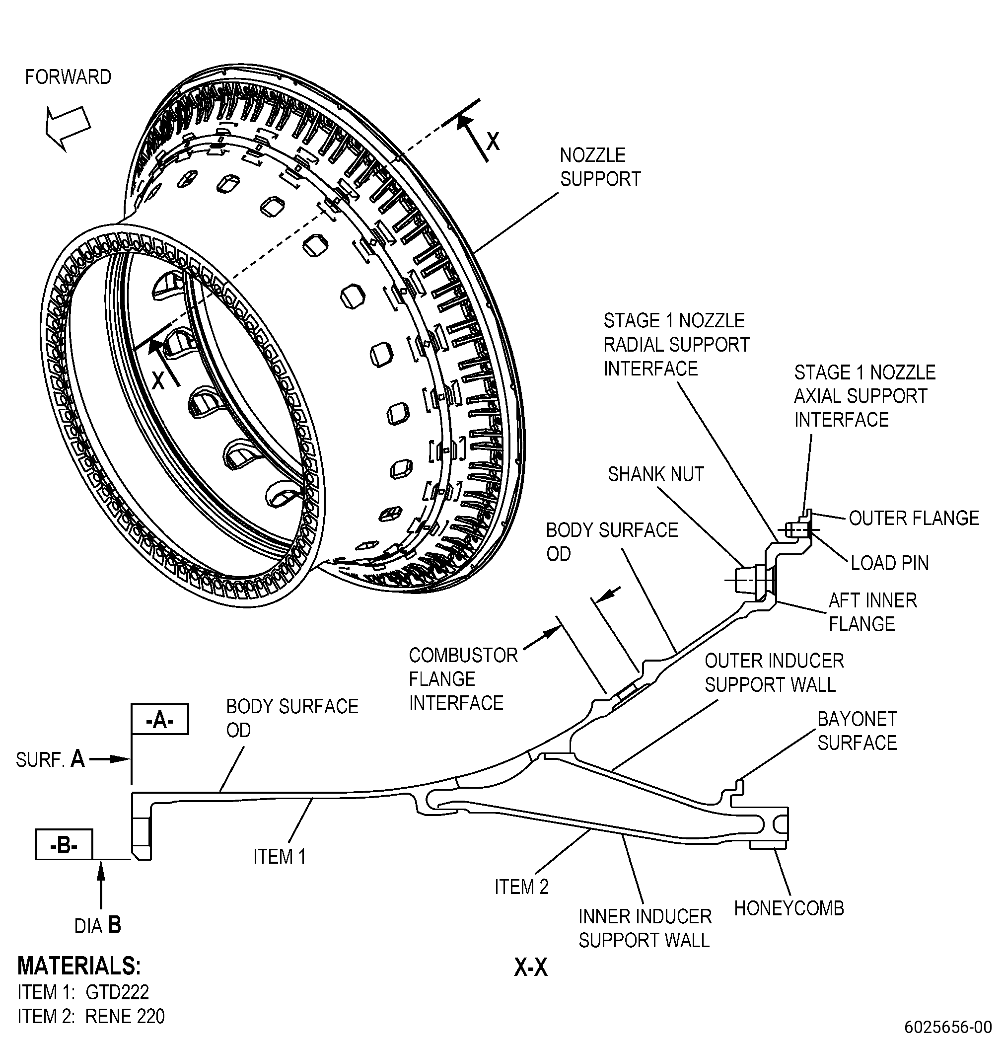
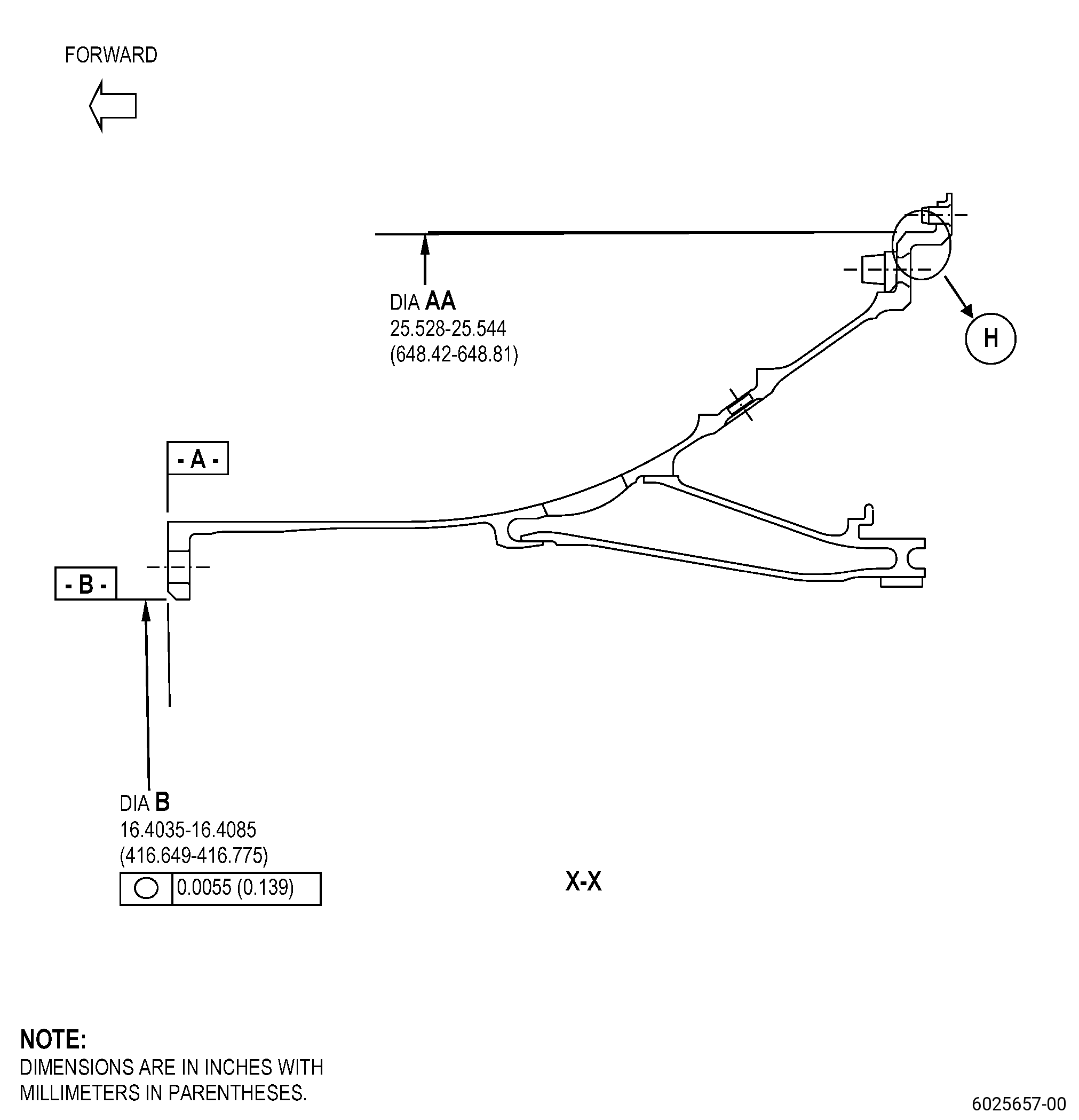
| A. | This procedure gives instructions to repair the high pressure turbine stage 1 nozzle support (nozzle support) by machining and thermal spraying diameter AA. Refer to Figure 901. |
| B. | The following maximum repairable limits apply to this repair: |
| NOTE: |
|
| (5) | Dimensional Inspection. |
| (e) | Do an inspection of the nozzle support for: |
| 1 | Diameter AA: |
| Minimum repairable limit: |
|
| C. | The subsequent table gives a list of the part numbers that are applicable to this procedure. All part numbers are applicable to all paragraphs unless specified differently. |
|
|||||||||||||||||||||||
| D. | Proprietary/Complex Process Statement. |
| (1) | None. |
| 2 . | Tools, Equipment, and Materials. |
| NOTE: |
|
| A. | Tools and Equipment. |
| (1) | Special Tools. None. |
| (2) | Standard Tools and Equipment. None. |
| (3) | Locally Manufactured Tools. None. |
| B. | Consumable Materials. |
| C. | Referenced Procedures. |
|
| D. | Expendable Parts. None. |
| E. | SPD Information. |
| (1) | Spare Supplied. None. |
| (2) | Protected Spares. None. |
| (3) | Locally Manufactured Spares. None. |
| F. | Special Solutions. None. |
| G. | Test Specimens. |
|
| 3 . | Dimensional Information. |
| Subtask 72-51-01-220-126 |
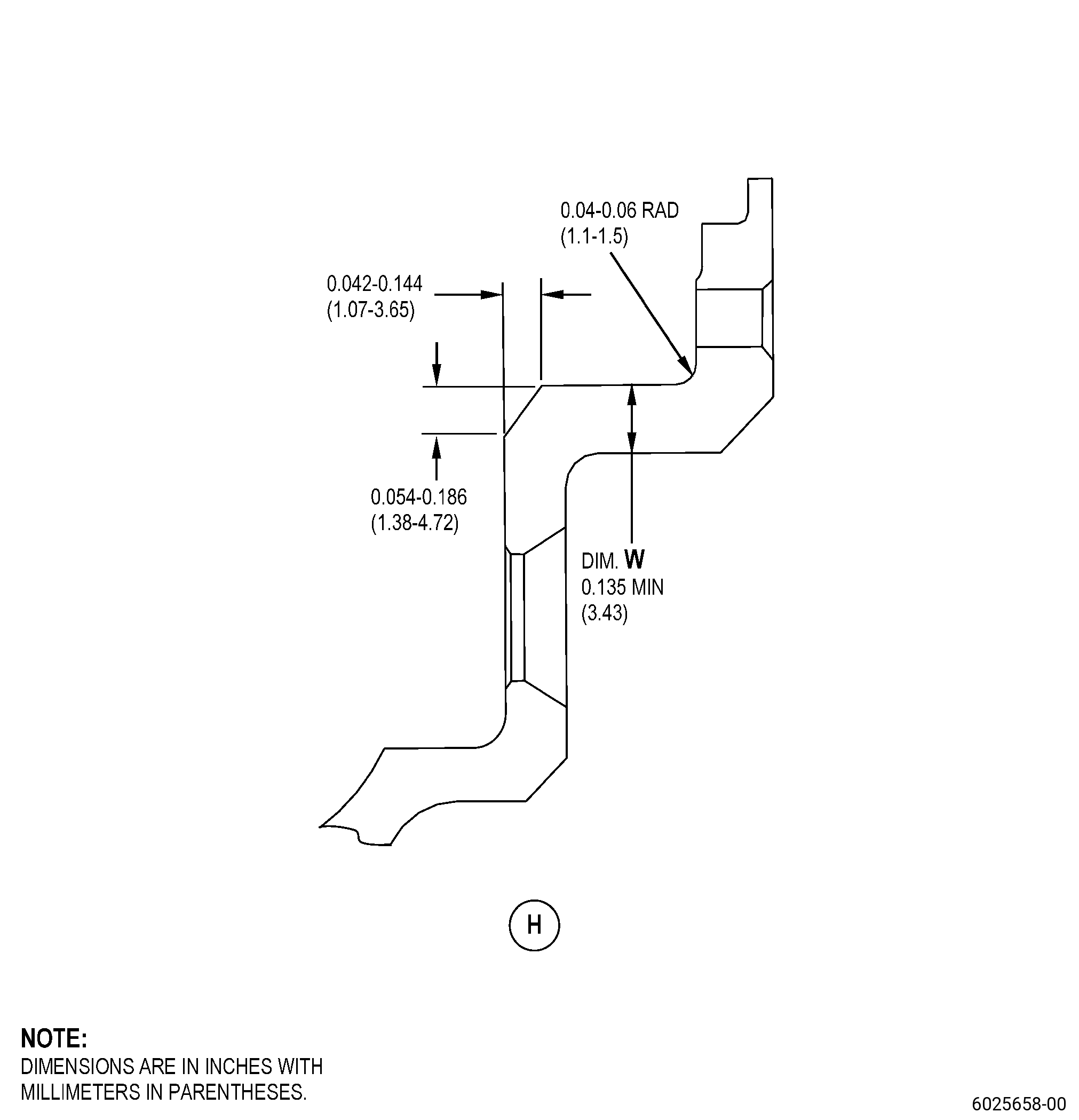
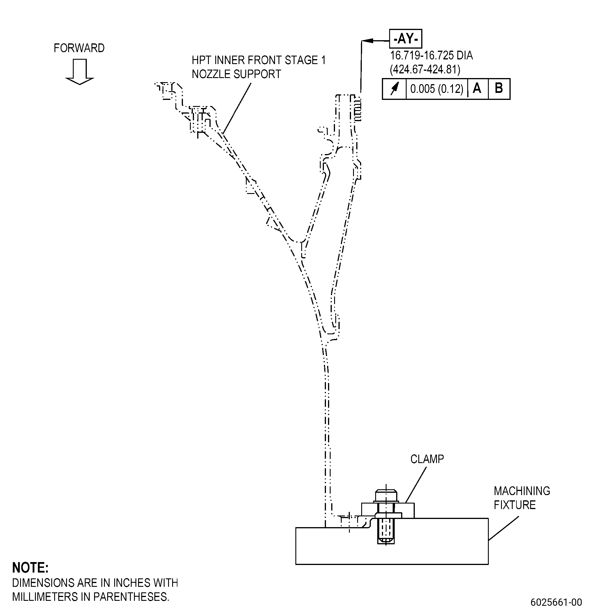
| A. | Refer to Figure 901 and Figure 902 for specified dimensions and locations. |
| NOTE: |
|
| NOTE: |
|
|
| 4 . | Setup Information. |
| Subtask 72-51-01-350-126 |
| A. | Set-up the nozzle support for machining. Refer to Figure 903, Figure 904, and as follows: |
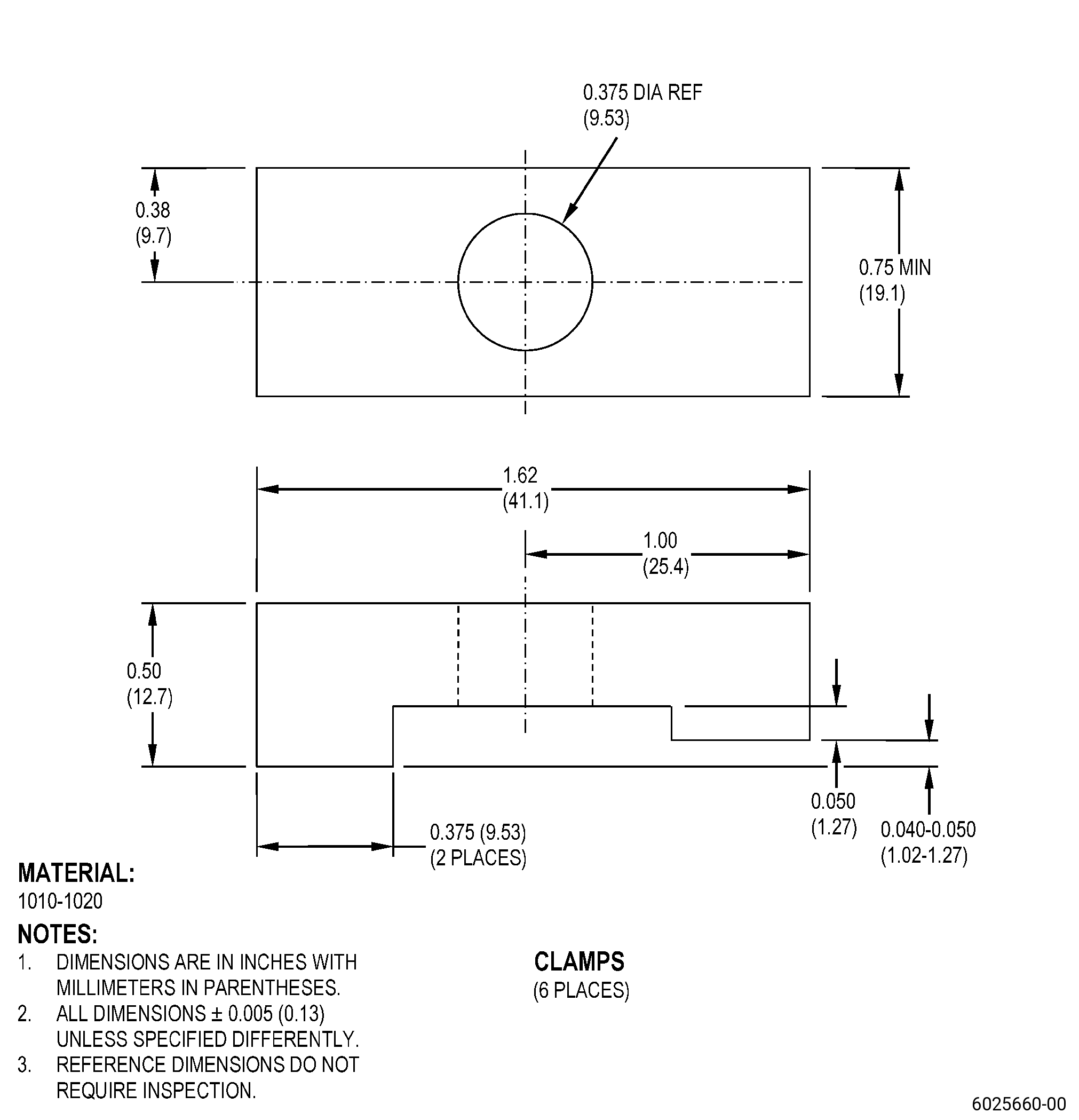
| (1) | If necessary, make the machining fixture. Refer to Figure 903. |
| (2) | Put the machining fixture on a clean machining table or an equivalent clean and flat surface. |
| (3) | Adjust the position of the machining fixture to get surface FA flat to 0.001 inch (0.02 mm) or less as follows: |
| (a) | If necessary, put C10-155 shims between surface FA of the machining fixture and the surface of the machining table to get surface FA of the machining fixture flat to 0.001 inch (0.02 mm) FIR or less. |
| (b) | Make sure that the runout of surface FS is 0.001 inch (0.02 mm) FIR or less. |
| (4) | Adjust the position of the machining fixture to get surface FB concentric to the machining table axis to 0.002 inch (0.05 mm) or less. |
| (5) | Attach the machining fixture to the machining table with clamps as follows: |
| (a) | Engage the clamps to attach the machining fixture to the machining table. |
| (6) | Measure the runout of surface FS and the concentricity of surface FB of the machining fixture as follows: |
| (a) | Make sure that the machining fixture agrees with the limits specified in Subtask 72-51-01-350-126 (paragraph 4.A.(3) thru paragraph 4.A.(4)). |
| (7) | If necessary, do a Subtask 72-51-01-350-126 (paragraph 4.A.(3) thru paragraph 4.A.(6)) again to adjust the machining fixture to the correct position. |
| (8) | Put the nozzle support on the machining fixture. Refer to Figure 903, Figure 904, and as follows: |
| (a) | Put the nozzle support on the machining fixture with surface A (datum A) of the nozzle support down on surface FS of the machining fixture. |
| (9) | Adjust the position of the nozzle support to get surface A flat to 0.002 inch (0.05 mm) or less. Refer to Figure 901, Figure 903, Figure 904, and as follows: |
| (a) | If necessary, put C10-155 shims between surface A (datum A) of the nozzle support and surface FS of the machining fixture. |
| (10) | Adjust the position of the nozzle support to make diameter of surface B (datum B) agree with the limits. Refer to Figure 901, Figure 904, and as follows: |
| (a) | If necessary, put C10-155 shims between surface B (datum B) of the nozzle support and surface FB of the machining fixture. |
| (11) | Attach the nozzle support to the machining fixture with a minimum of six clamps that are equally spaced. Refer to Figure 903. |
| 5 . | Procedure. |
| Subtask 72-51-01-110-040 |
| NOTE: |
|
| A. | Clean the nozzle support repair area. Refer to TASK 70-21-00-110-051 (CHEMICAL CLEANING), TASK 70-21-23-110-053 (CLEANING METHOD NO. 23 - HAND-WIPE DEGREASING), and as follows: |
| WARNING: |
|
| (1) | Use C04-003 acetone. |
| Subtask 72-51-01-230-037 |
| B. | Do an inspection of the nozzle support diameter AA. Refer to TASK 70-32-00-200-002 (INDIRECT INSPECTION METHODS), TASK 70-32-03-230-002 (SPOT-FLUORESCENT-PENETRANT INSPECTION), and as follows: |
| (1) | Use Class A penetrant. |
| (2) | Examine if diameter AA has thermal spray coating. |
| NOTE: |
|
| Subtask 72-51-01-320-017 |
| C. | If necessary, machine the nozzle support diameter AA. Refer to TASK 70-00-03-800-004 (MACHINING DATA), Figure 901, Figure 902, Subtask 72-51-01-220-126 (paragraph 3.A.), and as follows: |
| (1) | If there is sufficient material to agree with the finish dimensions, do a skim cut of the nozzle support diameter AA to remove defects. Go to Subtask 72-51-01-350-128 (paragraph 5.D.(4)) thru Subtask 72-51-01-230-038 (paragraph 5.D.(7)). |
| Subtask 72-51-01-350-127 |
| D. | Repair the nozzle support diameter AA as follows: |
| CAUTION: |
|
| 1 | If the nozzle support diameter AA has thermal spray coating, remove it as follows: |
| a | Remove the minimum material from diameter AA before you apply thermal spray coating. |
| b | Alternative Procedure Available. Remove the thermal spray coating from the nozzle support diameter AA. Refer to TASK 70-23-00-100-001 (STRIPPING PROCEDURES), TASK 70-23-23-330-008 (REMOVAL OF COATINGS BY HIGH PRESSURE WATER STRIPPING), Figure 902, and as follows: |
| (1) | If you cannot remove the thermal spray coating from diameter AA to its in-process dimension specified in Subtask 72-51-01-220-126 (paragraph 3.A.), you cannot repair the nozzle support with this procedure. |
| Subtask 72-51-01-320-018 |
| b.A. | Alternative Procedure. Machine the nozzle support diameter AA to remove the thermal spray coating. Refer to TASK 70-00-03-800-004 (MACHINING DATA), Subtask 72-51-01-220-126 (paragraph 3.A.), Figure 901, and as follows: |
| (1) | Set-up the nozzle support for machining. Refer to Subtask 72-51-01-350-126 (paragraph 4.A.). |
| CAUTION: |
|
| CAUTION: |
|
| (2) | Machine the nozzle support diameter AA to remove all wear, or fretting. Refer to TASK 70-00-03-800-004 (MACHINING DATA), and as follows: |
| (a) | If you cannot remove the wear, or fretting from diameter AA to its minimum in-process dimensions, you cannot repair the nozzle support with this procedure. |
| (2) | If the nozzle support diameter AA has no thermal spray coating, continue with the repair of diameter AA. Refer to Subtask 72-51-01-320-018 (paragraph 5.D.(3)). |
| (3) | Machine the nozzle support diameter AA. Refer to TASK 70-00-03-800-004 (MACHINING DATA), Subtask 72-51-01-220-126 (paragraph 3.A.), Figure 901, and as follows: |
| (a) | Set-up the nozzle support for machining. Refer to Subtask 72-51-01-350-126 (paragraph 4.A.). |
| CAUTION: |
|
| CAUTION: |
|
| (b) | Machine the nozzle support diameter AA to remove all thermal spray coating, wear, or fretting. Refer to TASK 70-00-03-800-004 (MACHINING DATA), and as follows: |
| 1 | If you cannot remove the wear, or fretting from diameter AA to its minimum in-process dimensions, you cannot repair the nozzle support with this procedure. |
| Subtask 72-51-01-350-128 |
| WARNING: |
|
| (4) | If necessary, blend the machined areas of the nozzle support. Refer to TASK 70-42-00-350-002 (BLENDING AND REMOVAL OF HIGH METAL PROCEDURES) and as follows: |
| (a) | Remove all burrs and break sharp edges to 0.005 to 0.010 inch (0.13 to 0.25 mm). |
| Subtask 72-51-01-160-032 |
| (5) | Clean the nozzle support diameter AA as follows: |
| WARNING: |
|
| (a) | Use a C10-182 cleaning cloth moist with C04-035 isopropyl alcohol. |
| (b) | Replace the dirty cleaning cloth with a new moist C10-182 cleaning cloth until it stays clean. |
| Subtask 72-51-01-230-038 |
| (6) | Etch the nozzle support diameter AA. Refer to TASK 70-24-00-110-033 (ETCHING PROCEDURES FOR FLUORESCENT-PENETRANT INSPECTION), TASK 70-24-01-110-034 (SWAB ETCHING PROCEDURE), and as follows: |
| (a) | Use Class C etchant. |
| (7) | Do an inspection of the nozzle support diameter AA. Refer to TASK 70-32-00-200-002 (INDIRECT INSPECTION METHODS), TASK 70-32-03-230-002 (SPOT-FLUORESCENT-PENETRANT INSPECTION), and as follows: |
| (a) | Use Class A penetrant. |
| (b) | Indications 0.030 inch (0.76 mm) or less in diameter are permitted. |
| (c) | Non-linear indications 0.060 inch (1.52 mm) or less with a minimum distance of 0.15 inch (3.9 mm) between indications are permitted. |
| (d) | Linear indications more than 0.030 inch (0.76 mm) are not permitted. |
| NOTE: |
|
| (e) | Through indications are not permitted. |
| (f) | Microshrinkage must agree with Photo Standard 8311253, Class 30. |
| Subtask 72-51-01-340-002 |
| WARNING: |
|
| (8) | Thermal-spray the nozzle support diameter AA. Refer to TASK 70-49-00-340-001 (THERMAL SPRAYING), TASK 70-49-21-340-022 (THERMAL SPRAYING NICKEL-CHROMIUM/ALUMINUM COMPOSITE (POWDER)), Subtask 72-51-01-220-126 (paragraph 3.A.), Figure 902, and as follows: |
| (a) | Make sure that you thermal-spray the cylindrical shape of diameter AA and you apply masking to all other areas before thermal spray repair. |
| (b) | Apply C10-012 masking tape or equivalent to the areas of the nozzle support that you will not thermal-spray. |
| (c) | Apply a sufficient quantity of aluminum-nickel chromium composite powder coating to machine to the finish dimensional limits. |
| NOTE: |
|
| (d) | Apply the thermal spray coating to the part and the test specimens to a sufficient thickness to machine the part to the finish dimensions. Make sure that you apply thermal spray coating to the test specimens at the same time and to the same thickness as the part. |
| (e) | Do all the quality assurance tests specified in TASK 70-49-21-340-022 (THERMAL SPRAYING NICKEL-CHROMIUM/ALUMINUM COMPOSITE (POWDER)). |
| CAUTION: |
|
| (f) | Remove all the masking tape or equivalent from the nozzle support. |
| Subtask 72-51-01-320-019 |
| (9) | Machine the nozzle support diameter AA. Refer to TASK 70-00-03-800-004 (MACHINING DATA), Subtask 72-51-01-220-126 (paragraph 3.A.), Figure 901, Figure 902, and as follows: |
| (a) | Set-up the nozzle support for machining. Refer to Subtask 72-51-01-350-126 (paragraph 4.A.). |
| (b) | Machine the nozzle support diameter AA to finish dimensions. Make sure that the minimum coating thickness is no less than 0.004 inch (0.11 mm). |
| Subtask 72-51-01-350-129 |
| WARNING: |
|
| (10) | If necessary, blend the machined areas of the nozzle support. Refer to TASK 70-42-00-350-002 (BLENDING AND REMOVAL OF HIGH METAL PROCEDURES). |
| Subtask 72-51-01-220-127 |
| (11) | Do a visual inspection of the nozzle support diameter AA for thermal spray coating as follows: |
| (a) | Chipping, flaking, and separated coating are not permitted. |
| (b) | The coating must have full constant coverage in the spray areas. |
| (c) | If the thermal spray coating on diameter AA does not agree with the limits, remove the thermal spray coating and apply it again. Refer to Subtask 72-51-01-350-127 (paragraph 5.D.(1)) thru Subtask 72-51-01-220-127 (paragraph 5.D.(11)). |
| E. | Do a final inspection of the nozzle support. Refer to Task 72-51-01-200-801 (72-51-01, INSPECTION 001). |