| GENX-1B CLEANING,INSPECTION,AND REPAIR MANUAL | Dated: 11/15/2024 | |
| CIR 72-51-01 , REPAIR 003 | ||
| HIGH PRESSURE TURBINE STAGE 1 NOZZLE SUPPORT - REPAIR - DIMENSIONAL RESTORATION | ||
| GENX-1B CLEANING,INSPECTION,AND REPAIR MANUAL | Dated: 11/15/2024 | |
| CIR 72-51-01 , REPAIR 003 | ||
| HIGH PRESSURE TURBINE STAGE 1 NOZZLE SUPPORT - REPAIR - DIMENSIONAL RESTORATION | ||
| * * * FOR ALL |
| TASK 72-51-01-300-803 |
| 1 . | Dimensional Restoration. |
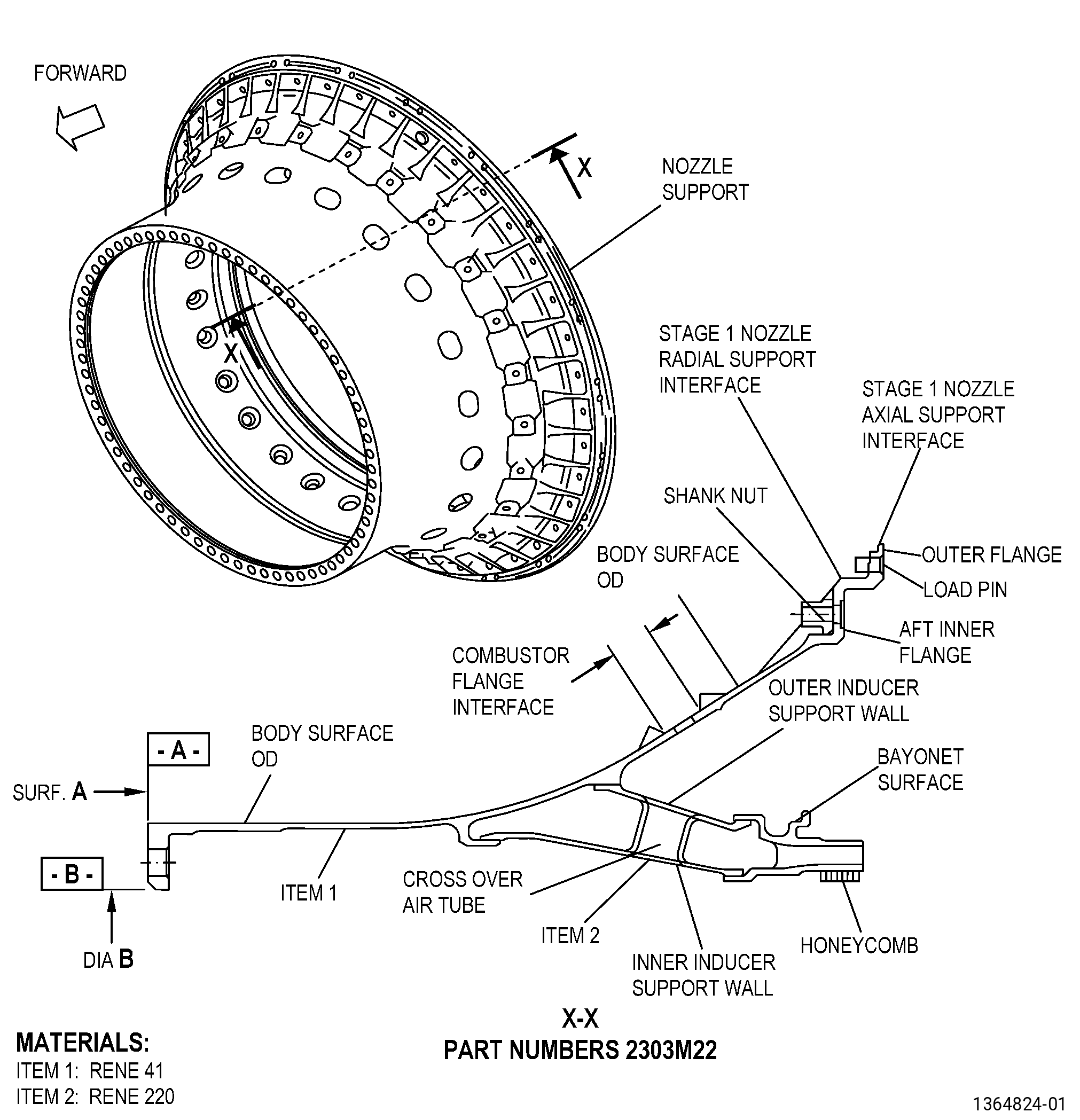
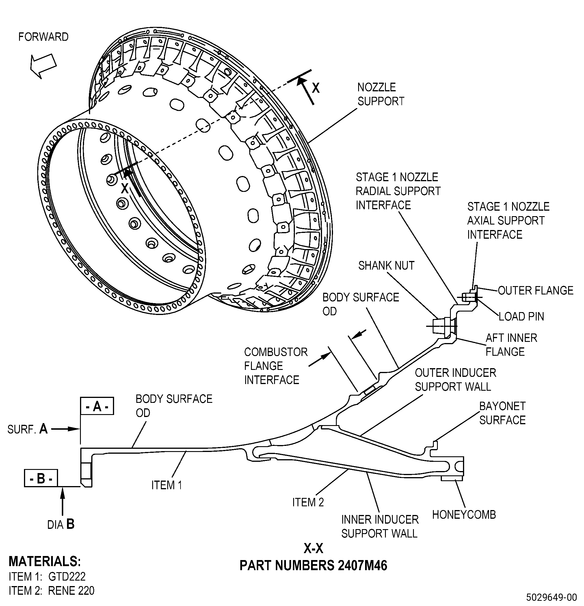
| A. | This procedure gives instructions to repair the high pressure turbine stage 1 nozzle support (nozzle support) by heat-treating the nozzle support to restore dimensions. Refer to Figure 901. |
| B. | The following maximum repairable limits apply to this repair: |
| NOTE: |
|
| (5) | Dimensional Inspection. |
| Refer to Figure 803 and Figure 803A. |
| (e) | Do an inspection of the nozzle support for: |
| 1 | Diameter AA: |
| Maximum repairable limit: |
|
| 2 | Runout at diameter AA: |
| Maximum repairable limit: |
|
| 3 | Diameter BA: |
| Maximum repairable limit: |
|
| 5 | Diameter CA: |
| Maximum repairable limit: |
|
| 6 | Runout of surface DA (surface A restrained flat within 0.002 inch (0.05 mm)): |
| Maximum repairable limit: |
|
| 8 | Dimension FF: |
| Maximum repairable limit: |
|
| 9 | Dimension H: |
| Maximum repairable limit: |
|
| 10 | Diameter B: |
| Maximum repairable limit: |
|
| C. | The subsequent table gives a list of the part numbers that are applicable to this repair. All part numbers are applicable to all paragraphs unless specified differently. |
|
||||||||||||||||||||||||||||||||||||
| D. | Proprietary/Complex Process Statement. |
| (1) | None. |
| 2 . | Tools, Equipment, and Materials. |
| NOTE: |
|
| A. | Tools and Equipment. |
| (1) | Special Tools. None. |
| (2) | Standard Tools and Equipment. None. |
| (3) | Locally Manufactured Tools. |
|
| B. | Consumable Materials. |
|
| C. | Referenced Procedures. |
| D. | Expendable Parts. None. |
| E. | SPD Information. |
| (1) | Locally Manufactured SPD. None. |
| F. | Special Solutions. None. |
| G. | Test Specimens. None. |
| 3 . | Dimensional Information. |
| Subtask 72-51-01-220-056 |
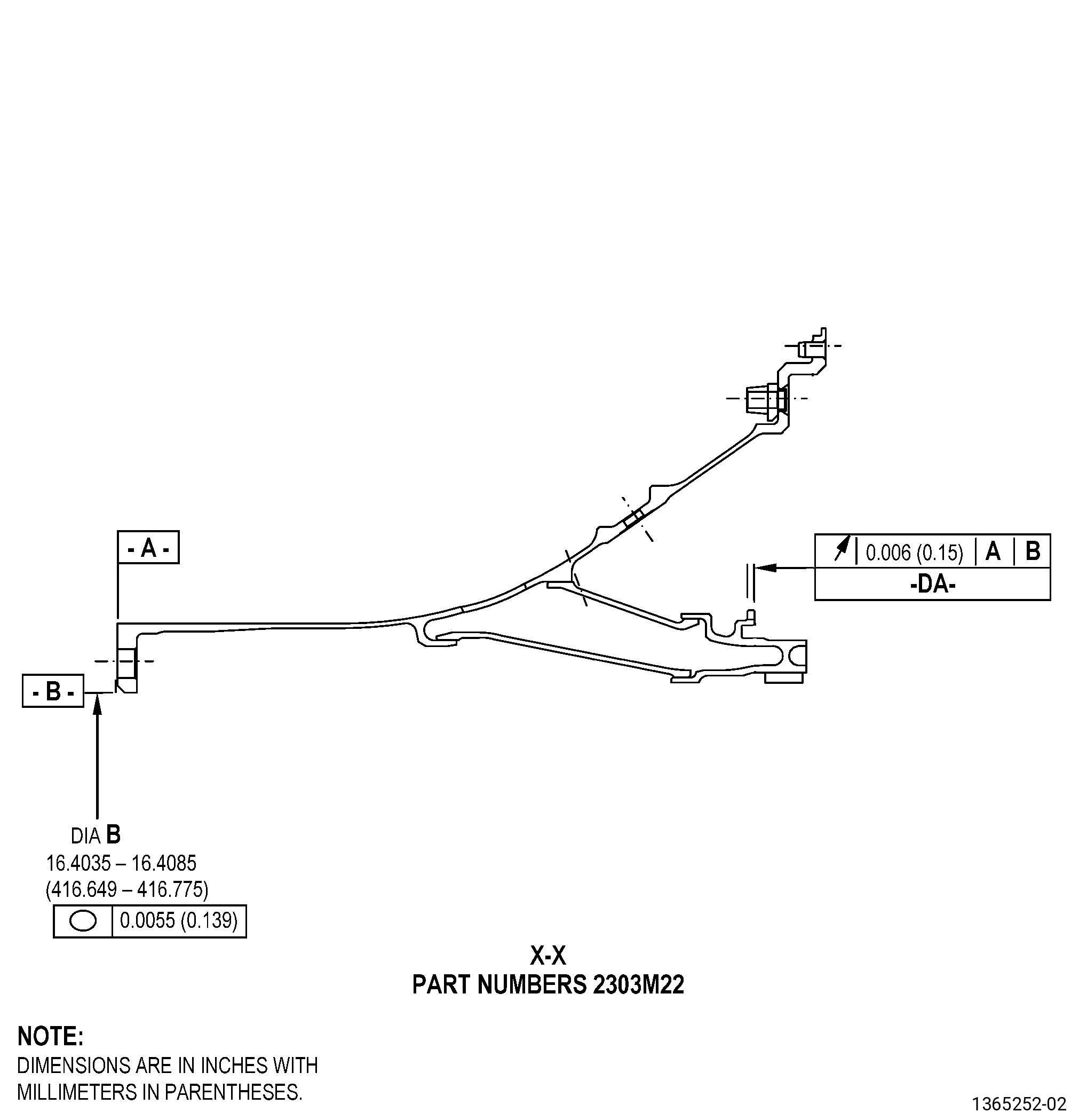
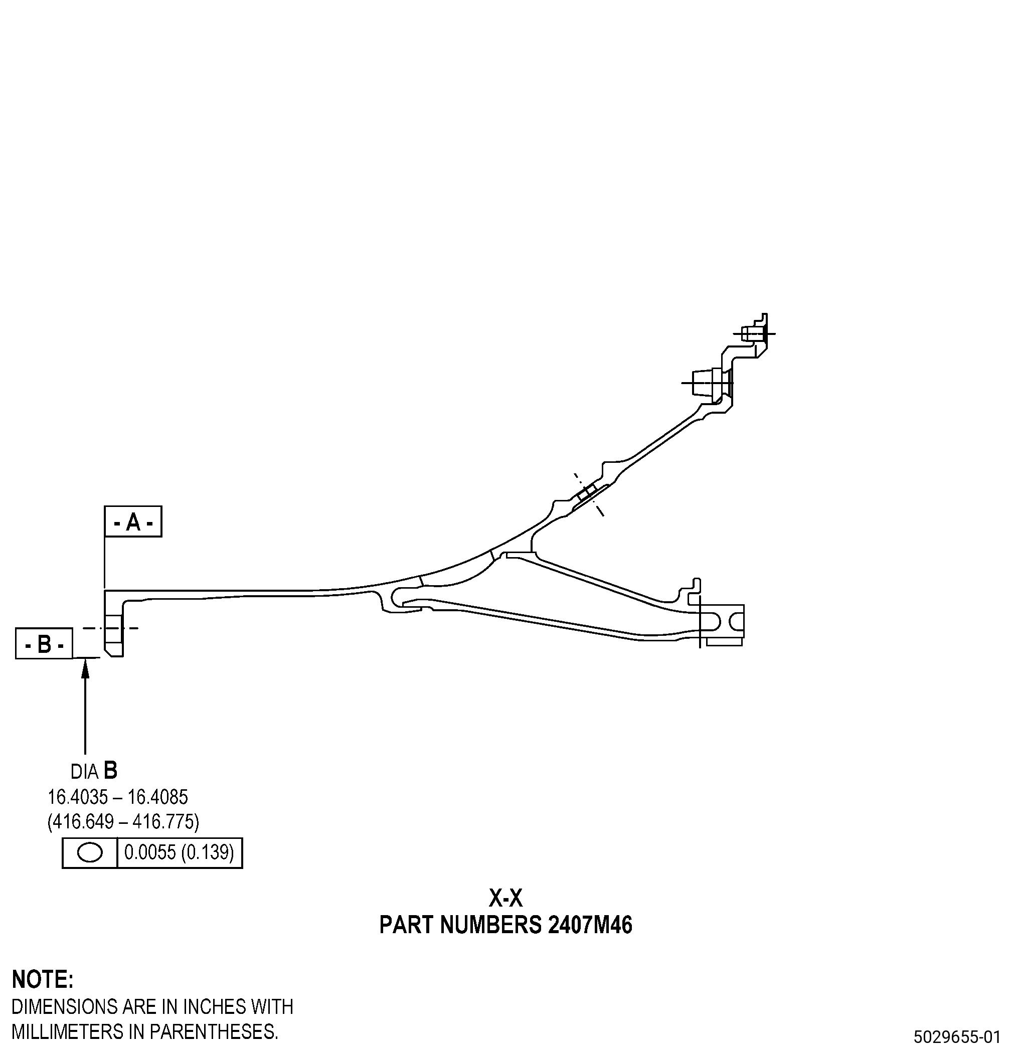
| A. | Refer to Figure 901 for specified dimensions and locations. |
| NOTE: |
|
| NOTE: |
|
| NOTE: |
|
| NOTE: |
|
| 4 . | Setup Information. |
| Subtask 72-51-01-350-022 |
| A. | Set-up the nozzle support for inspection. Refer to Figure 902, Figure 903, and as follows: |
| Subtask 72-51-01-930-003 |
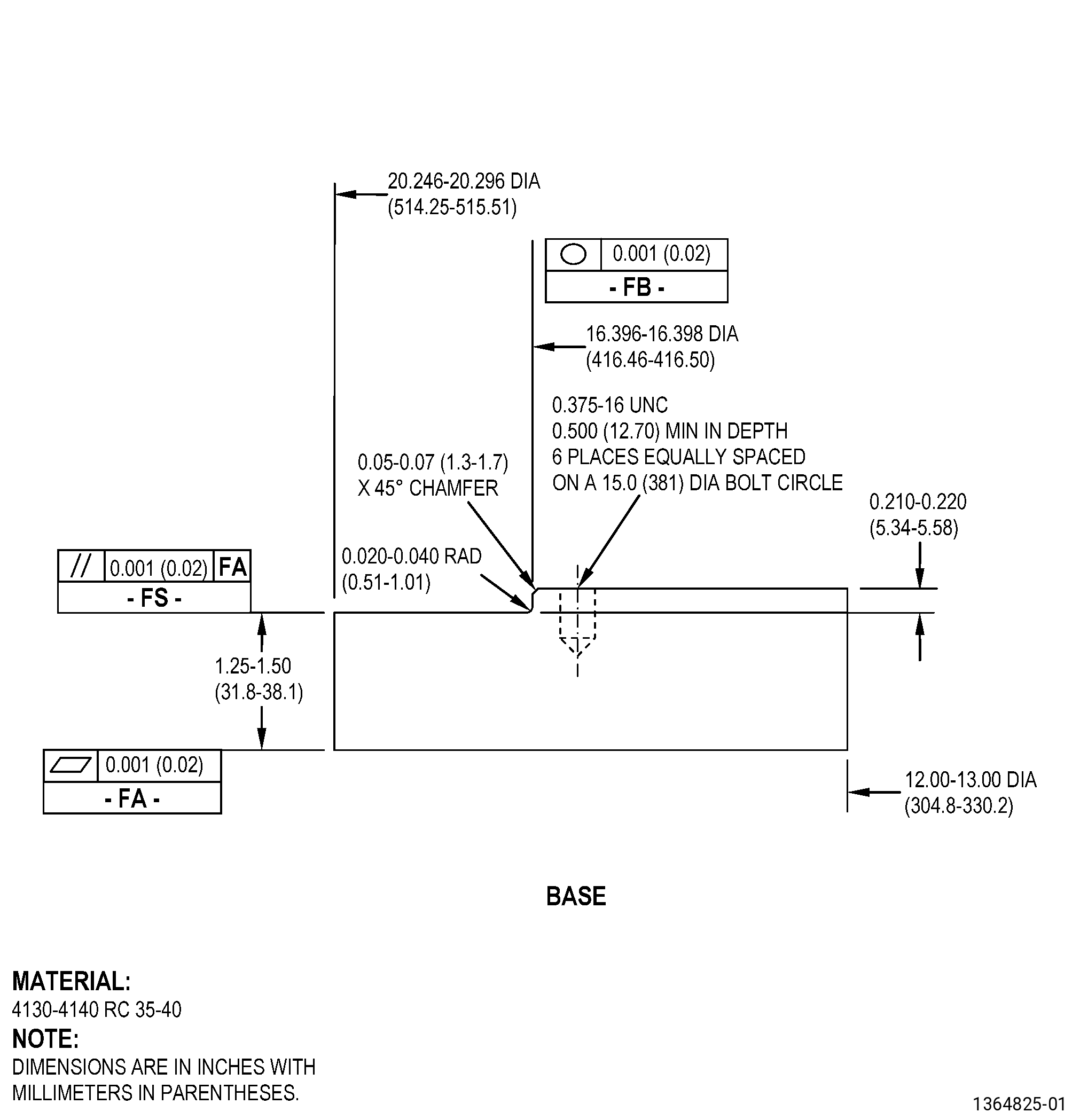
| (1) | If necessary, make the inspection fixture. Refer to Figure 902. |
| Subtask 72-51-01-350-023 |
| (2) | Put the inspection fixture on a clean machining table or an equivalent clean and flat surface. |
| Subtask 72-51-01-350-024 |
| (3) | Adjust the position of the inspection fixture to make sure that the runout of surface FS is 0.001 inch (0.02 mm) FIR or less. If necessary, put C10-155 shims between surface FA of the inspection fixture and the surface of the machining table. |
| (4) | Adjust the position of the inspection fixture to get surface FB concentric to the machining table axis to 0.002 inch (0.05 mm) or less. |
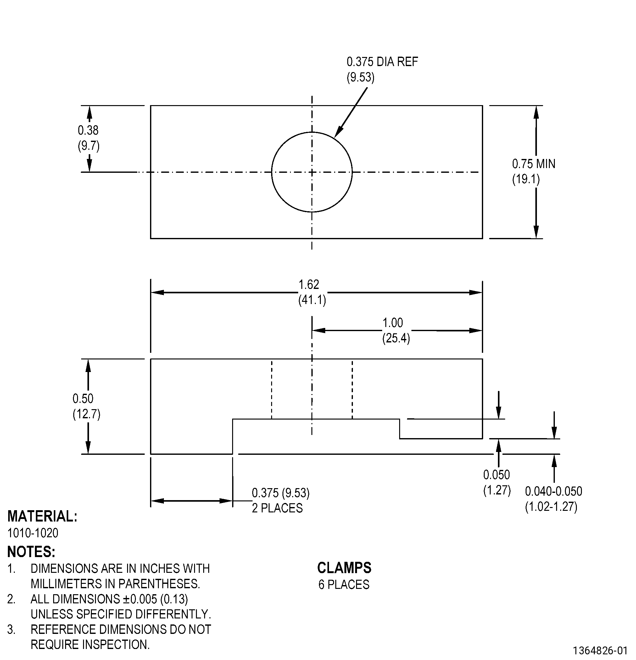
| (5) | Attach the inspection fixture to the machining table with clamps as follows: |
| (a) | Engage the clamps to attach the inspection fixture to the machining table. |
| Subtask 72-51-01-220-058 |
| (6) | Measure the runout of surface FS and the concentricity of surface FB of the inspection fixture as follows: |
| (a) | Make sure that the inspection fixture agrees with the limits specified in Subtask 72-51-01-350-024 (paragraph 4.A.(3) and paragraph 4.A.(4)). |
| Subtask 72-51-01-350-025 |
| (7) | If necessary, do Subtask 72-51-01-350-024 (paragraph 4.A.(3)) thru Subtask 72-51-01-220-058 (paragraph 4.A.(6)) again to adjust the inspection fixture to the correct position. |
| (8) | Put the nozzle support on the inspection fixture as follows: |
| (a) | Put the nozzle support on the inspection fixture with surface A (datum A) of the nozzle support down on surface FS of the inspection fixture. |
| Subtask 72-51-01-350-026 |
| (9) | Adjust the position of the nozzle support to get surface A (datum A) flat to 0.002 inch (0.05 mm) or less as follows: |
| (a) | If necessary, put C10-155 shims between surface A (datum A) of the nozzle support and surface FS of the inspection fixture. |
| (10) | Adjust the position of the nozzle support to get the diameter B (datum B) roundness to 0.0055 inch (0.139 mm) or less as follows: |
| (a) | If necessary, put C10-155 shims between diameter B (datum B) of the nozzle support and surface FB of the inspection fixture. |
| (11) | Attach the nozzle support to the inspection fixture with a minimum of six clamps that are equally spaced. |
| Subtask 72-51-01-350-027 |
| B. | Set-up the nozzle support for heat treatment. Refer to Figure 904 and as follows: |
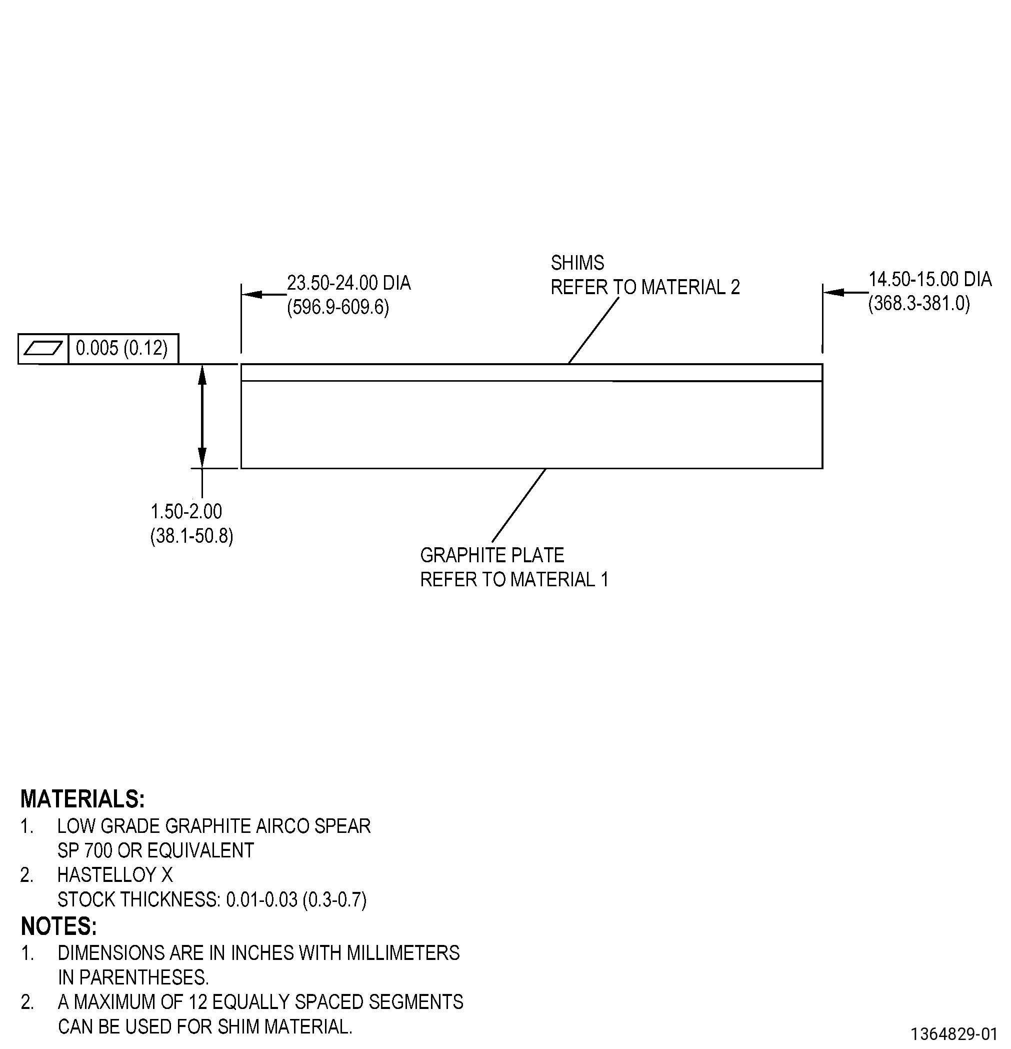
| (1) | Put Hastelloy X shims on top of a graphite plate as follows: |
| (a) | Put the Hastelloy X shims on top of a graphite plate to make sure that the nozzle support will not touch the graphite plate directly during the heat treatment. |
| CAUTION: |
|
| (2) | Put the nozzle support forward flange (surface A) on the Hastelloy X shims that are equally spaced on the top surface of the graphite plate. |
| NOTE: |
|
| (3) | For the quantity and placement requirements of the load thermocouples, refer to TASK 70-44-03-370-004 (FURNACE HEAT TREATMENT) . |
| Subtask 72-51-01-350-131 |
| C. | Set-up the nozzle support for a skim cut of Diameter B: |
| (1) | If necessary, make the machining fixture. |
| (2) | Put the machining fixture on a clean machining table or an equivalent clean and flat surface. |
| (3) | Adjust the position of the machining fixture to get surface where the aft flange will be supported flat to 0.001 inch (0.02 mm) or less as follows: |
| (a) | If necessary, put C10-155 shims between the surface of the machining fixture and surface of the machining table to get surface of the machining fixture flat to 0.001 inch (0.02 mm) FIR or less. |
| (b) | Make sure that the runout of the surface is 0.001 inch (0.02 mm) FIR or less. |
| (4) | Adjust the position of the machining fixture to get surface concentric to the machining table axis to 0.002 inch (0.05 mm) or less. |
| (5) | Attach the machining fixture to the machining table with clamps. |
| (6) | Put the nozzle support on the machining fixture and do as follows: |
| (a) | Put the nozzle support on the machining fixture with aft flange of the nozzle support down on surface of the machining fixture. |
| (7) | Adjust the position of the nozzle support to get surface A flat to 0.002 inch (0.05 mm) or less. |
| (8) | Adjust the position of the nozzle support to get the diameter of surface B (datum B) to agree with the limits. Refer to Figure 901. |
| (9) | Attach the nozzle support to the machining fixture with a minimum of six clamps that are equally-spaced. |
| 5 . | Procedure. |
| Subtask 72-51-01-100-005 |
| A. | If necessary, clean the nozzle support. Refer to TASK 72-51-01-100-801 (72-51-01, CLEANING 001). |
| Subtask 72-51-01-300-003 |
| B. | Remove the shank nuts from the nozzle support. Refer to TASK 72-51-01-300-801 (72-51-01, REPAIR 001). |
| Subtask 72-51-01-350-115 |
| C. | For part numbers 2407M46G06 and 2407M46G08 , remove the hard coating from the nozzle support. Refer to TASK 72-51-01-300-811 (72-51-01, REPAIR 011). |
| Subtask 72-51-01-370-014 |
| D. | Optional Procedure. Alternative Procedure Available. Heat-treat the nozzle support. Refer to TASK 70-44-00-800-010 (HEAT TREATING), TASK 70-44-03-370-004 (FURNACE HEAT TREATMENT) , and as follows: |
| NOTE: |
|
| (1) | Set-up the nozzle support for heat treatment. Refer to Subtask 72-51-01-350-027 (paragraph 4.B.). |
| (2) | Do a solution heat treatment of the nozzle support as follows: |
| (a) | Use a vacuum of 1.0 micron of mercury or less. |
| (b) | Increase the temperature of the nozzle support to a temperature range of 1835 to 1885°F (1002 to 1029°C) and keep the temperature for 20-30 minutes. |
| (c) | Decrease the temperature of the nozzle support to 1000°F (538°C) in less than 30 minutes. |
| Subtask 72-51-01-370-015 |
| D.A. | Optional Procedure. Alternative Procedure. Heat-treat the nozzle support. Refer to TASK 70-44-00-800-010 (HEAT TREATING), TASK 70-44-03-370-004 (FURNACE HEAT TREATMENT) , and as follows: |
| NOTE: |
|
| (1) | Set-up the nozzle support for heat treatment. Refer to Subtask 72-51-01-350-027 (paragraph 4.B.). |
| (2) | Do a solution heat treatment of the nozzle support as follows: |
| (a) | Use a vacuum of 1.0 micron of mercury or less. |
| (b) | Increase the temperature of the nozzle support to a temperature range of 1700 to 1750°F (927 to 954°C) and as follows: |
| 1 | Keep this temperature for 10-15 minutes or until the vacuum rate gets back to a vacuum pressure of 5.0 X 10⁻⁴ mm Hg or less (6.7x10⁻⁴ millibar). |
| (c) | Increase the temperature of the nozzle support to a temperature range of 1875 to 1925ºF (1024 to 1052ºC) at a rate of 20 to 25ºF (11 to 14ºC) for each minute and as follows: |
| 1 | Keep this temperature for a maximum of 3-5 minutes. |
| NOTE: |
|
| CAUTION: |
|
| (d) | Decrease the temperature of the nozzle support to a temperature range of 1750 to 1800ºF (954 to 982ºC) at a minimum rate of 20ºF (11ºC) for each minute and as follows: |
| 1 | Keep this temperature for 10-15 minutes. |
| (e) | Decrease the temperature of the nozzle support to 975 to 1025ºF (524 to 552ºC) in 30 minutes or less. |
| NOTE: |
|
| (f) | Remove the nozzle support from the furnace. |
| Subtask 72-51-01-370-016 |
| E. | If necessary, resize the aft flange to required dimensions with use of expander or static fixtures. |
| (1) | Resizing process can be aided by convection furnace heat treatment. Maximum temperature during heating process not to exceed 1025ºF (552ºC). |
| Subtask 72-51-01-220-080 |
| F. | Optional Procedure. Do an inspection of the nozzle support. Refer to TASK 72-51-01-200-801 (72-51-01, INSPECTION 001). |
| Subtask 72-51-01-300-004 |
| G. | For P/N 2303M22G03 , P/N 2303M22G04 , P/N 2303M22G05 , and P/N 2303M22G06 , heat-treat the nozzle support. Refer to TASK 70-44-00-800-010 (HEAT TREATING), TASK 70-44-03-370-004 (FURNACE HEAT TREATMENT) , and as follows: |
| Subtask 72-51-01-350-028 |
| (1) | Set-up the nozzle support for heat treatment. Refer to Subtask 72-51-01-350-027 (paragraph 4.B.), Setup Information. |
| Subtask 72-51-01-370-002 |
| (2) | Alternative Procedure Available. Do a solution heat treatment of the nozzle support as follows: |
| (a) | Use a vacuum of 1.0 micron of mercury or less. |
| (b) | Increase the temperature of the nozzle support to a range of 1835 to 1885°F (1002 to 1029°C) and keep the temperature for 20-30 minutes. |
| (c) | Decrease the temperature of the nozzle support to 1000°F (538°C) in less than 30 minutes. |
| Subtask 72-51-01-370-017 |
| (2).A. | Alternative Procedure. Do a solution heat treatment of the nozzle support as follows: |
| (a) | Use a vacuum of 1.0 micron of mercury or less. |
| (b) | Increase the temperature of the nozzle support to a range of 1700 to 1750ºF (927 to 954ºC) and as follows: |
| 1 | Keep this temperature for 10-15 minutes or until the vacuum rate gets back to a vacuum pressure of 5.0 X 10⁻⁴ mm Hg or less (6.7x10⁻⁴ millibar). |
| (c) | Increase the temperature of the nozzle support to a temperature range of 1875 to 1925ºF (1024 to 1052ºC) at a rate of 20 to 25ºF (11 to 14ºC) for each minute and as follows: |
| 1 | Keep this temperature for a maximum of 3-5 minutes. |
| NOTE: |
|
| CAUTION: |
|
| (d) | Decrease the temperature of the nozzle support to a temperature range of 1750 to 1800ºF (954 to 982ºC) at a minimum rate of 20ºF (11ºC) for each minute and as follows: |
| 1 | Keep this temperature for 10-15 minutes. |
| (e) | Decrease the temperature of the nozzle support to 975 to 1025ºF (524 to 552ºC) in 30 minutes or less. |
| NOTE: |
|
| (f) | Remove the nozzle support from the furnace. |
| Subtask 72-51-01-370-020 |
| (3) | Do an age heat treatment to the nozzle support as follows: |
| (a) | Use Cycle V-13 or Cycle I-9. |
| Subtask 72-51-01-370-004 |
| G.A. | For part numbers 2407M46G02 , 2407M46G04 , 2407M46G06 , and 2407M46G08 heat-treat the nozzle support. Refer to TASK 70-44-00-800-010 (HEAT TREATING), and TASK 70-44-03-370-004 (FURNACE HEAT TREATMENT) , and do as follows: |
| Subtask 72-51-01-350-029 |
| (1) | Set-up the nozzle support for heat treatment. Refer to Subtask 72-51-01-350-027 (paragraph 4.B.). |
| Subtask 72-51-01-370-005 |
| (2) | Alternative Procedure Available. Do a solution heat treatment of the nozzle support as follows: |
| (a) | Use a vacuum of 1.0 micron of mercury or less. |
| (b) | Increase the temperature of the nozzle support to a range of 1835 to 1885°F (1002 to 1029°C) and keep the temperature for 20-30 minutes. |
| (c) | Decrease the temperature of the nozzle support to 1000°F (538°C) in less than 30 minutes. |
| Subtask 72-51-01-370-018 |
| (2).A. | Alternative Procedure. Do a solution heat treatment of the nozzle support as follows: |
| (a) | Use a vacuum of 1.0 micron of mercury or less. |
| (b) | Increase the temperature of the nozzle support to a range of 1700 to 1750ºF (927 to 954ºC) and as follows: |
| 1 | Keep this temperature for 10-15 minutes or until the vacuum rate gets back to a vacuum pressure of 5.0 X 10⁻⁴ mm Hg or less (6.7x10⁻⁴ millibar). |
| (c) | Increase the temperature of the nozzle support to a temperature range of 1875 to 1925ºF (1024 to 1052ºC) at a rate of 20 to 25ºF (11 to 14ºC) for each minute and as follows: |
| 1 | Keep this temperature for a maximum of 3-5 minutes. |
| NOTE: |
|
| CAUTION: |
|
| (d) | Decrease the temperature of the nozzle support to a temperature range of 1750 to 1800ºF (954 to 982ºC) at a minimum rate of 20ºF (11ºC) for each minute and as follows: |
| 1 | Keep this temperature for 10-15 minutes. |
| (e) | Decrease the temperature of the nozzle support to 975 to 1025ºF (524 to 552ºC) in 30 minutes or less. |
| NOTE: |
|
| (f) | Remove the nozzle support from the furnace. |
| Subtask 72-51-01-370-019 |
| (3) | Do an age heat treatment to the nozzle support as follows: |
| (a) | Age the nozzle support at 1450 to 1500°F (788 to 815°C) for 8 hours. |
| (b) | Decrease the temperature of the nozzle support to 1000°F (538°C) at a rate not less than 25°F (13.89°C) per minute. |
| (c) | Decrease the nozzle support temperature to room temperature. |
| (d) | Remove the nozzle support from the furnace. |
| Subtask 72-51-01-220-062 |
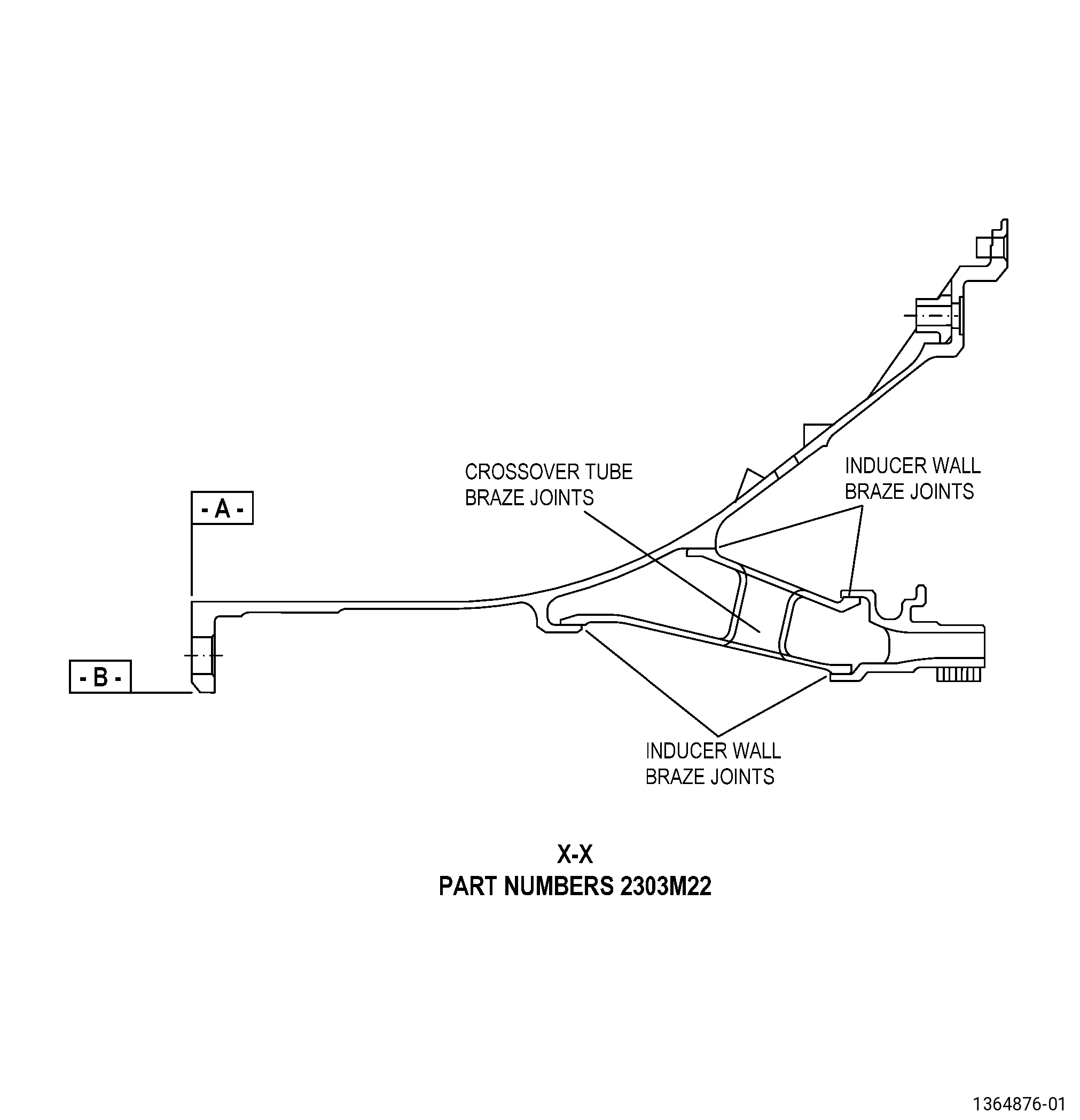
| H. | Do an inspection in the nozzle support brazed areas as follows. Refer to TASK 70-41-00-310-001 (WELDING AND BRAZING PRACTICES), TASK 70-41-03-310-004 (HIGH TEMPERATURE FURNACE BRAZE), and as follows: |
| (1) | The diameter or length of one void and non-bonded areas must not be more than the 0.08 inch (2.0 mm). |
| (2) | There must not be more than three voids or non-bonded areas per 1 inch (25 mm) of braze metal. |
| (3) | Irregular surface porosity is permitted. Indications of 0.015 inch (0.38 mm) or less are not considered as interpretable. |
| (4) | Through voids are not permitted. |
| Subtask 72-51-01-220-063 |
| I. | Do an inspection of the honeycomb. Refer to TASK 70-33-02-220-005 (CAPILLARY INSPECTION OF OPEN FACE HONEYCOMB STRUCTURES) and as follows: |
| NOTE: |
|
| (1) | Honeycomb core shall be completely bonded to its backing surface in 80 percent of the total contact area. |
| (2) | Unbonded areas may contain no more than ten (10) totally unbonded adjacent cells circumferentially by five (5) totally unbonded adjacent cells axially. |
| (3) | Honeycomb core node bond is uninterpretable. |
| (4) | Unbonded areas must be separated by at least five (5) adjacent bonded cells. |
| (5) | An unbonded area shall not include any open cells, partial cells or splices. |
| Subtask 72-51-01-110-015 |
| J. | Deleted. |
| Subtask 72-51-01-200-005 |
| K. | Do an inspection of the nozzle support. Refer to TASK 70-32-00-200-002 (INDIRECT INSPECTION METHODS), TASK 70-32-02-230-001 (FLUORESCENT PENETRANT INSPECTION), and as follows: |
| (1) | Use Class C penetrant. |
| (2) | Indications 0.030 inch (0.76 mm) or less are not interpretable and are permitted. |
| (3) | Indications 0.060 inch (1.52 mm) or less with minimum distance of 0.15 inch (3.9 mm) are permitted. |
| (4) | No through indications are permitted. |
| Subtask 72-51-01-100-006 |
| L. | Clean the nozzle support. Refer to TASK 70-21-00-110-051 (CHEMICAL CLEANING) and TASK 70-21-03-160-001 (CLEANING METHOD NO. 3 - STEAM CLEANING). |
| Subtask 72-51-01-370-003 |
| WARNING: |
|
| M. | If necessary, dry the nozzle support in an oven at a temperature range of 130 to 150°F (54 to 66°C) for 30 minutes minimum. |
| Subtask 72-51-01-200-006 |
| N. | Do a dimensional inspection of the nozzle support. Refer to TASK 72-51-01-200-801 (72-51-01, INSPECTION 001), Figure 901, Figure 903, and as follows: |
| (1) | Set-up the nozzle support for inspection. Refer to Subtask 72-51-01-350-022 (paragraph 4.A.), Setup Information. |
| (2) | Measure the clearance between the nozzle support surface A (datum A) and the inspection fixture surface FS to make sure that the flatness of surface A (datum A) is a maximum of 0.002 inch (0.05 mm). |
| (3) | Do an inspection of the dimension and the runout of diameter AY to make sure that they agree with the limits. |
| Subtask 72-51-01-220-132 |
| O. | Do an inspection of Diameter B: |
| (1) | If Diameter B measures less than 16.4035 inches (416.65 mm), but more than 16.3935 inches (416.40 mm), do a skim cut repair of Diameter B to a maximum diametrical limit of 0.010 inch (0.25 mm). Refer to TASK 70-00-03-800-004 (MACHINING DATA) and the Subtask 72-51-01-350-027 (paragraph 4.B.) to set-up the part. |
| (2) | If Diameter B measures less than 16.3935 inches (416.40 mm), this part is not repairable with this method. |
| (3) | If Diameter B measures more than 16.4085 inches (416.78 mm), this part is not repairable with this method. |
| Subtask 72-51-01-160-033 |
| P. | If a skim cut was performed, clean the part. Refer to TASK 72-51-01-100-801 (72-51-01, CLEANING). |
| Subtask 72-51-01-110-041 |
| Q. | If a skim cut was performed, etch machined areas. Refer to TASK 70-24-01-110-034 (SWAB ETCHING PROCEDURE) and as follows: |
| (1) | Use Class C etchant. |
| Subtask 72-51-01-230-039 |
| R. | If a skim cut was performed, do a machined area inspection. Refer to TASK 70-32-03-230-002 (SPOT-FLUORESCENT-PENETRANT INSPECTION) and as follows: |
| (1) | Use Class A penetrant. |
| (2) | Indications 0.030 inch (0.76 mm) or less are not interpretable and are permitted. |
| (3) | Non-linear indications 0.060 inch (1.52 mm) or less with a minimum distance of 0.15 inch (3.9 mm) between indications are permitted. |
| (4) | Linear indications more than 0.030 inch (0.76 mm) are not permitted. |
| NOTE: |
|
| (5) | Through indications are not permitted. |
| Subtask 72-51-01-200-007 |
| S. | Do an inspection of the nozzle support. Refer to TASK 72-51-01-200-801 (72-51-01, INSPECTION 001). |
| Subtask 72-51-01-350-116 |
| T. | For part numbers 2407M46G06 and 2407M46G08 , apply the hard coating from the nozzle support. Refer to TASK 72-51-01-300-811 (72-51-01, REPAIR 011). |
| Subtask 72-51-01-300-005 |
| U. | Install the shank nuts to the nozzle support. Refer to TASK 72-51-01-300-801 (72-51-01, REPAIR 001). |