| GENX-1B CLEANING,INSPECTION,AND REPAIR MANUAL | Dated: 02/03/2021 | |
| CIR 72-53-40 , REPAIR 010 | ||
| HIGH PRESSURE TURBINE ROTOR STAGE 1 DISK - REPAIR - POST INSPECTION SHOTPEENING REPAIR | ||
| GENX-1B CLEANING,INSPECTION,AND REPAIR MANUAL | Dated: 02/03/2021 | |
| CIR 72-53-40 , REPAIR 010 | ||
| HIGH PRESSURE TURBINE ROTOR STAGE 1 DISK - REPAIR - POST INSPECTION SHOTPEENING REPAIR | ||
| * * * FOR ALL |
| TASK 72-53-40-300-807 |
| 1 . | Post Inspection Shotpeening Repair. |
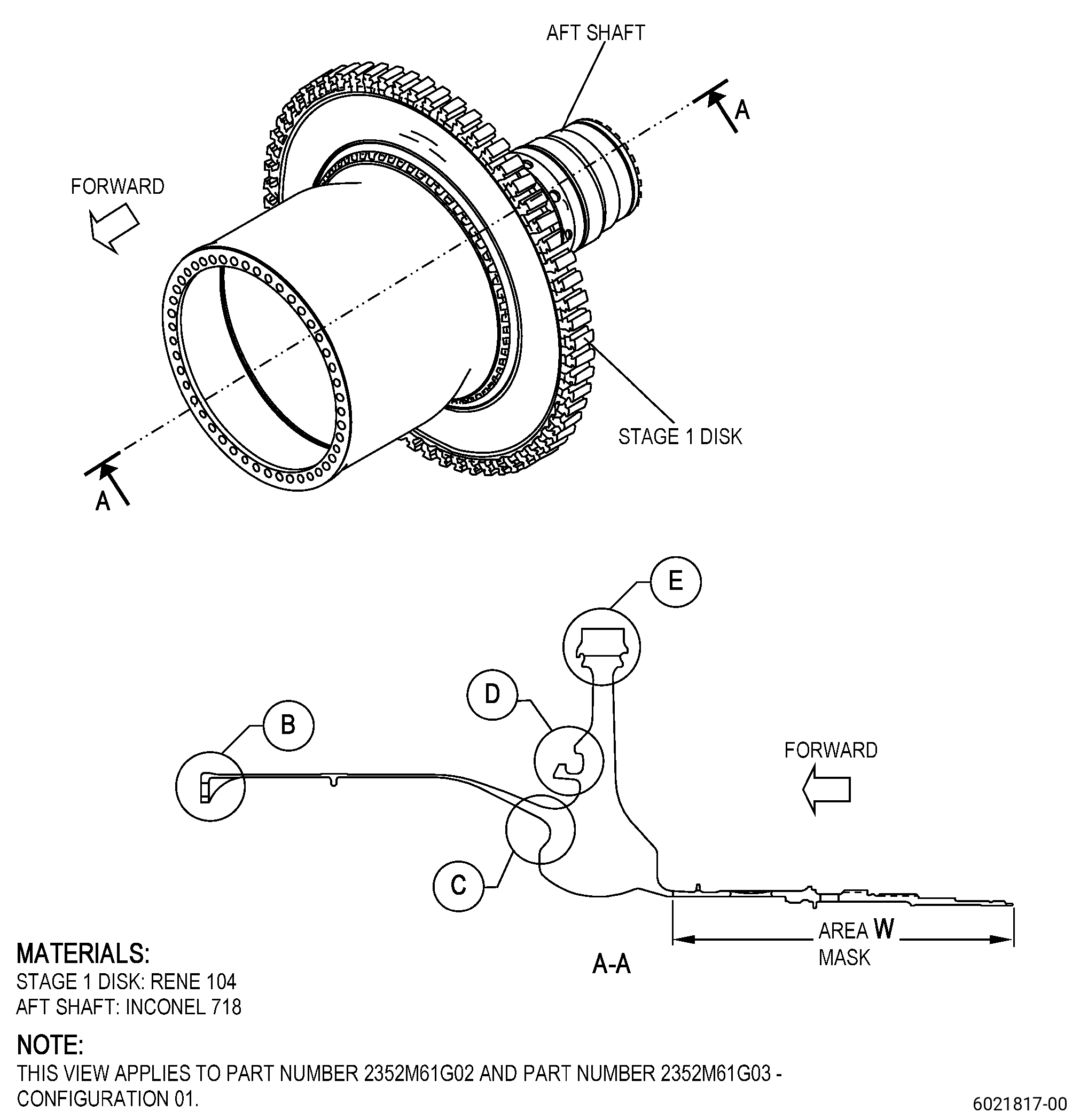
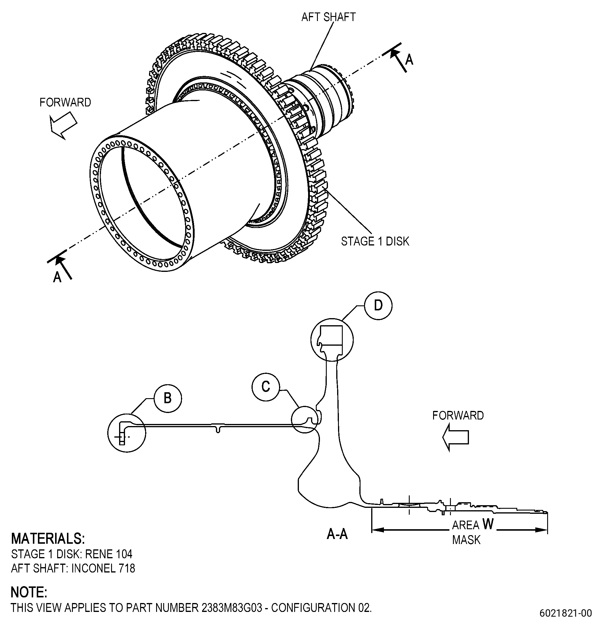
| A. | This procedure gives instructions to repair the high pressure turbine rotor stage 1 disk (disk) by doing a shotpeening procedure. Refer to Figure 901. |
| B. | The following maximum repairable limits apply to this repair: |
| NOTE: |
|
| (6) | Post Inspection Procedure. |
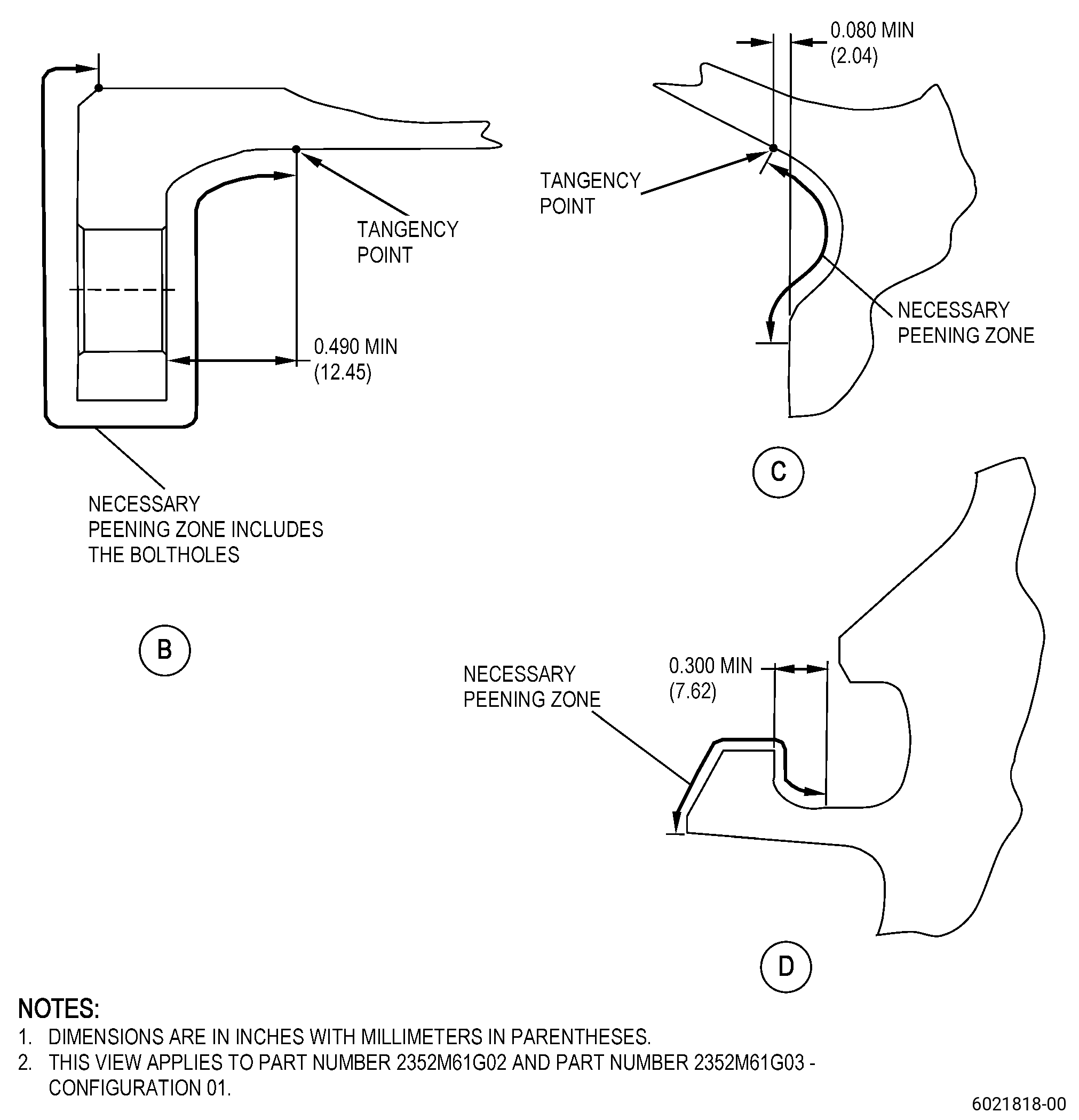
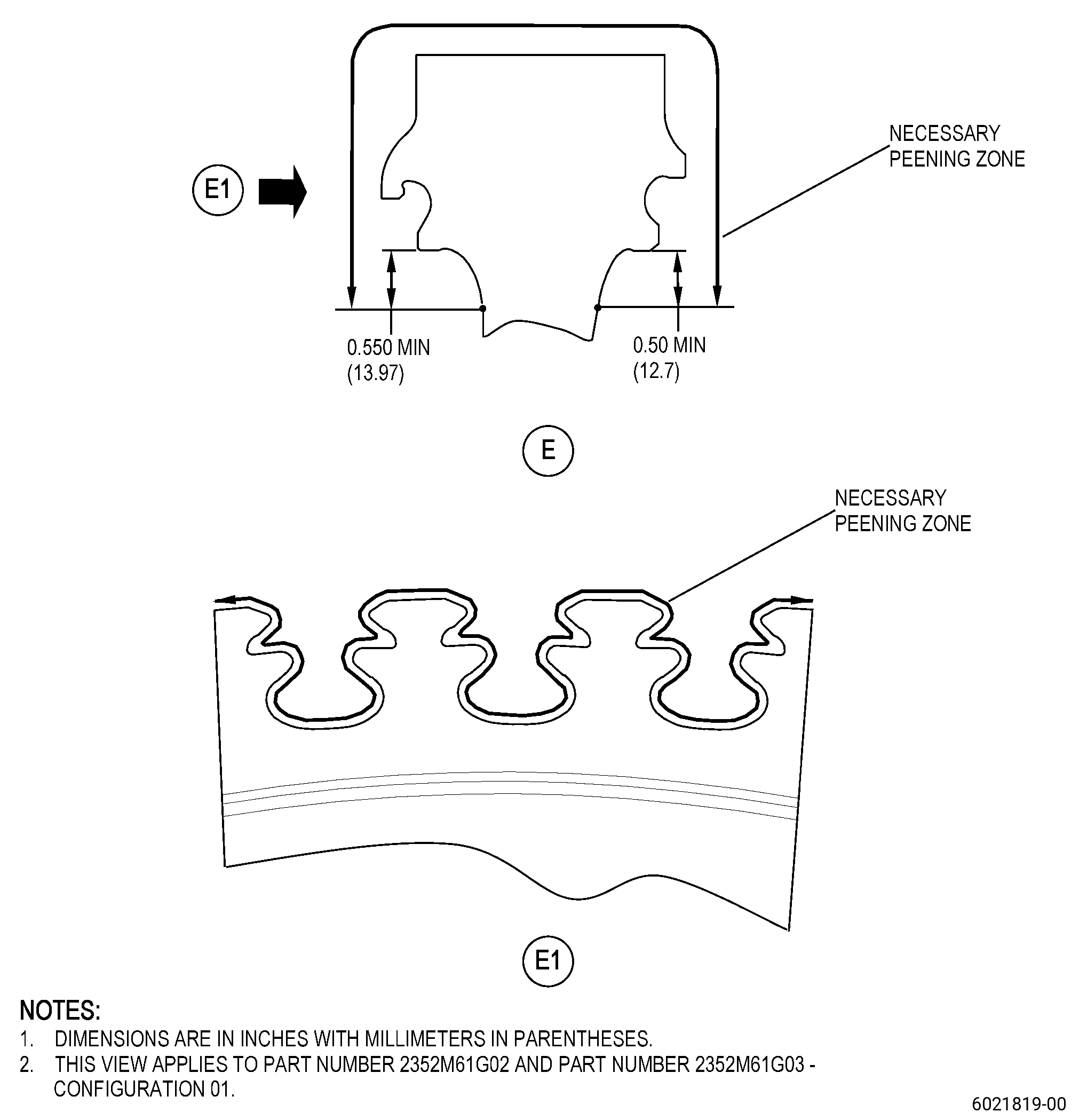
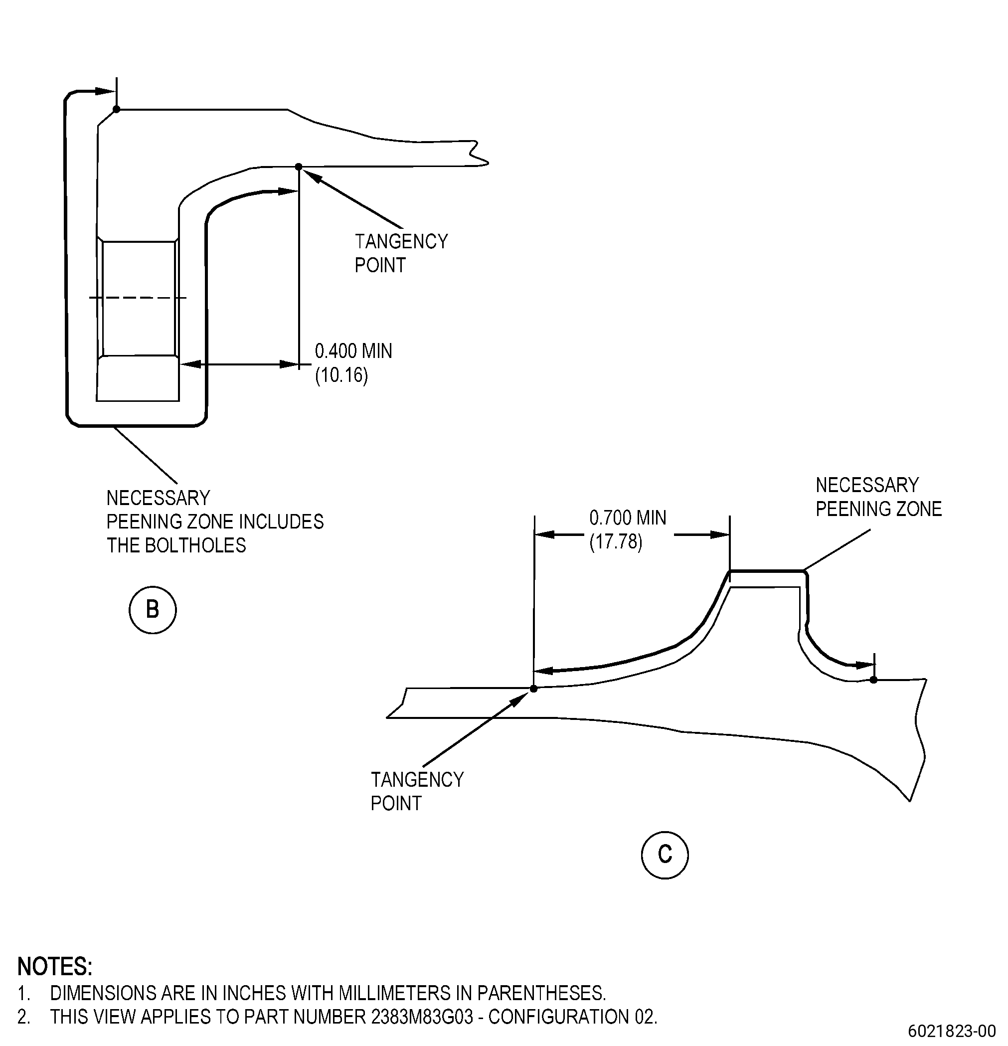
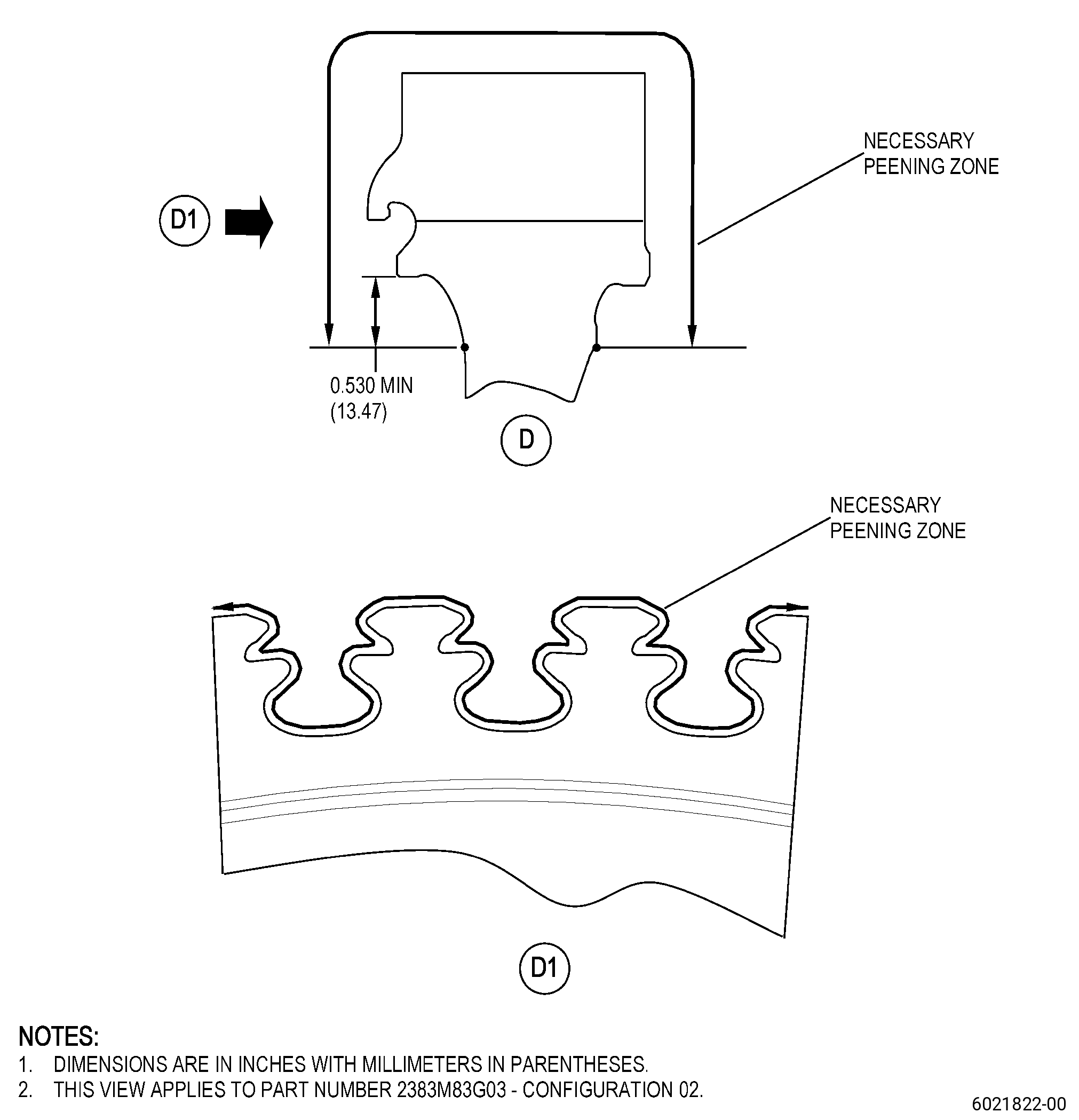
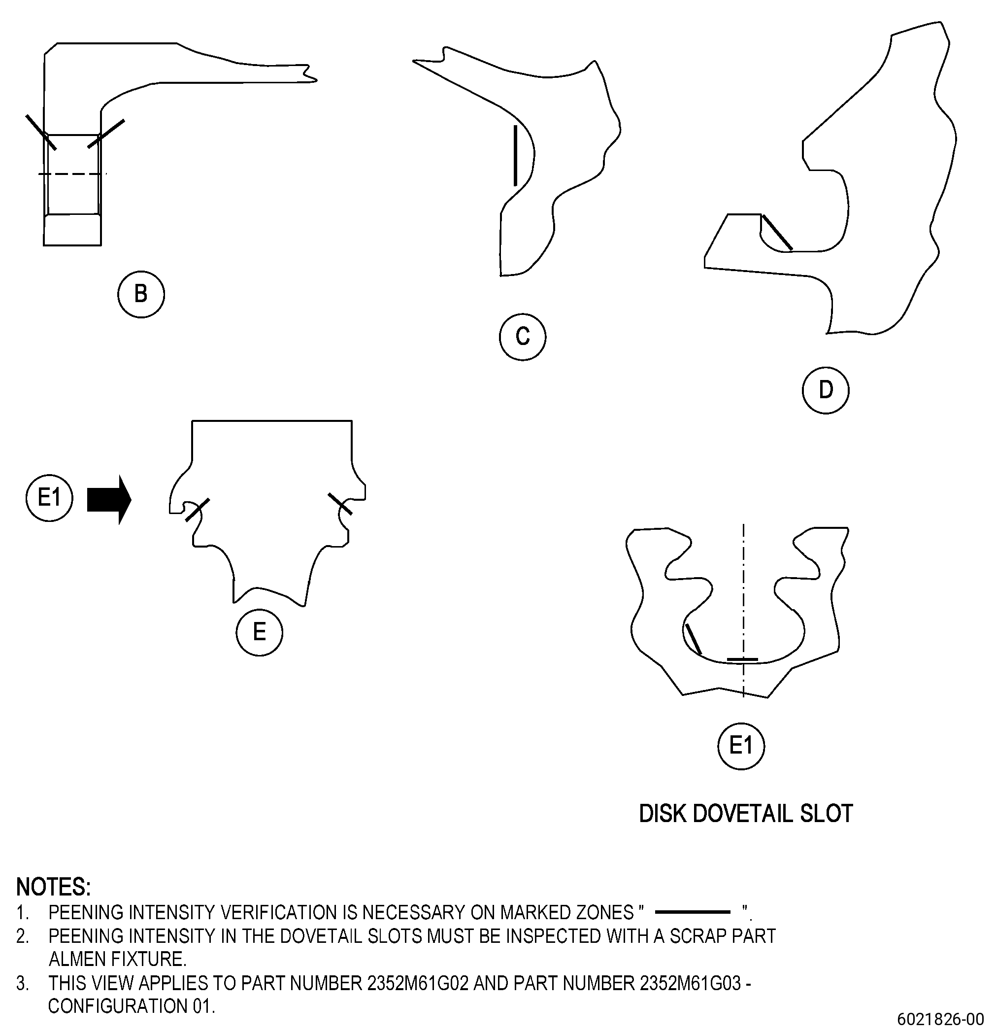
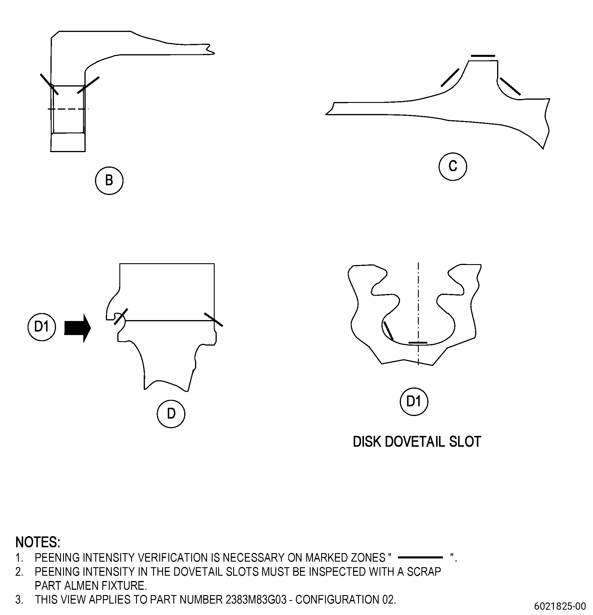
| (a) | Shotpeen the surfaces in the marked zones. Refer to Figure 816 and TASK 72-53-40-300-807 (72-53-40, REPAIR 010). |
| Maximum repairable limit: |
|
| C. | The subsequent table gives a list of the part numbers that are applicable to this repair. All part numbers are applicable to all paragraphs unless specified differently. |
|
|||||||||||||||||||||||
| D. | Proprietary/Complex Process Statement. |
| (1) | None. |
| 2 . | Tools, Equipment, and Materials. |
| NOTE: |
|
| A. | Tools and Equipment. |
| (1) | Special Tools. None. |
| (2) | Standard Tools and Equipment. None. |
| (3) | Locally Manufactured Tools. None. |
| B. | Consumable Materials. |
|
| C. | Referenced Procedures. |
| D. | Expendable Parts. None. |
| E. | SPD Information. |
| (1) | Spares Supplied. None. |
| (2) | Protected Spares. None. |
| (3) | Locally Manufactured SPD. None. |
| F. | Special Solutions. None. |
| G. | Test Specimens. None. |
| 3 . | Dimensional Information. |
| Subtask 72-53-40-220-236 |
| A. | Refer to Figure 901 for specified dimensions and locations. |
| NOTE: |
|
| NOTE: |
|
| 4 . | Setup Information. |
| None. |
| 5 . | Procedure. |
| Subtask 72-53-40-160-014 |
| A. | If necessary, clean the disk. Refer to TASK 72-53-40-100-801 (72-53-40, CLEANING 001). |
| Subtask 72-53-40-350-017 |
| B. | Peen the disk surfaces in the marked zones. Refer to TASK 70-47-01-380-016 (SHOTPEENING), Figure 901, Figure 902, and do as follows: |
| NOTE: |
|
| (1) | Apply masking with C01-021 plastic tape to the internal and external surfaces of area W. Refer to Figure 901. |
| NOTE: |
|
| (2) | Use C04-166 CCW 14 steel shot. |
| (3) | Peen to an intensity of 0.006-0.012N. |
| (4) | Coverage must be a minimum of 125 percent. |
| (5) | Direct impingement is necessary. |
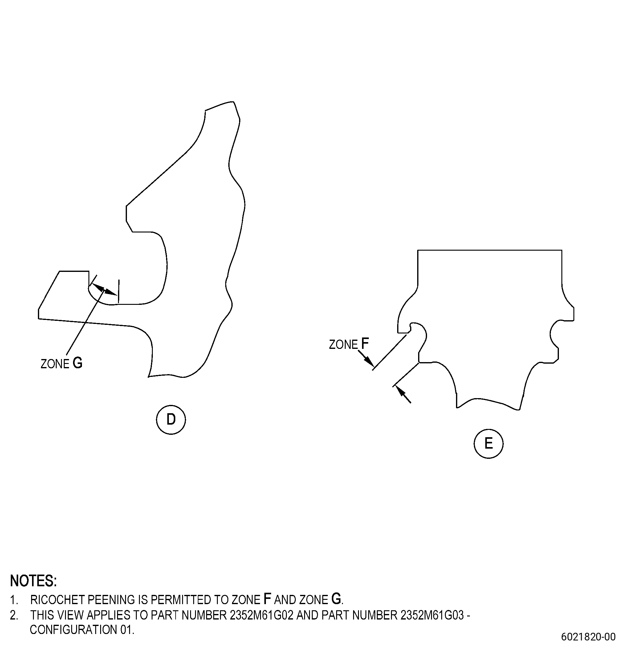
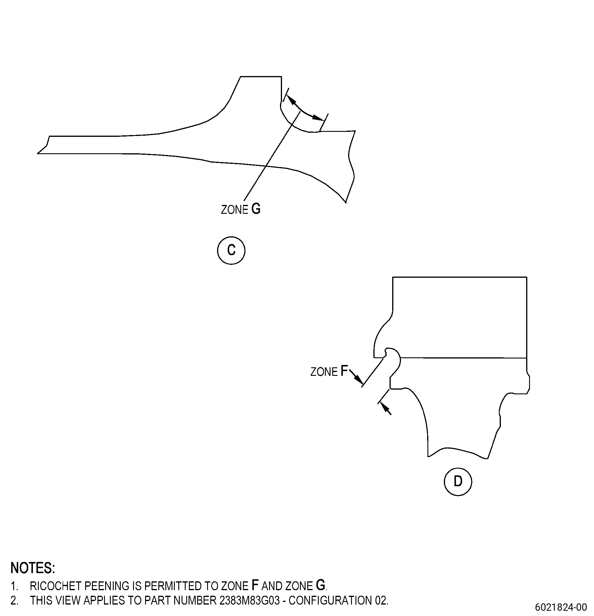
| (6) | Ricochet peening is permitted in zone F and zone G. |
| (7) | Lance peening is required to shotpeen the dovetail slots. |
| (8) | Impingement angle must be a minimum of 35 degrees. |
| (9) | Overspray is permitted in the areas adjacent to repair areas. |
| NOTE: |
|
| (10) | Refer to Figure 902 for intensity verification locations and as follows: |
| (a) | Do an inspection of the intensity in all the disk repaired areas with C10-205 Almen test strips and an Almen test strip holder. |
| (b) | Use a scrap part fixture for dovetail slot areas and a simulative fixture for other peened zones. |
| (11) | Remove the masking. |
| WARNING: |
|
| (12) | Use clean shop air to remove remaining particles from the disk. |
| Subtask 72-53-40-160-017 |
| C. | If necessary, clean the disk. Refer to TASK 70-21-00-110-051 (CHEMICAL CLEANING) and TASK 70-21-03-160-001 (CLEANING METHOD NO. 3 - STEAM CLEANING). |
| Subtask 72-53-40-220-238 |
| D. | Do a final visual inspection of the disk. Refer to TASK 72-53-40-200-801 (72-53-40, INSPECTION 001 - CONFIGURATION 01) and TASK 72-53-40-200-801 (72-53-40, INSPECTION 001 - CONFIGURATION 02). |