| GENX-1B CLEANING,INSPECTION,AND REPAIR MANUAL | Dated: 09/27/2021 | |
| CIR 72-53-43 , REPAIR 004 | ||
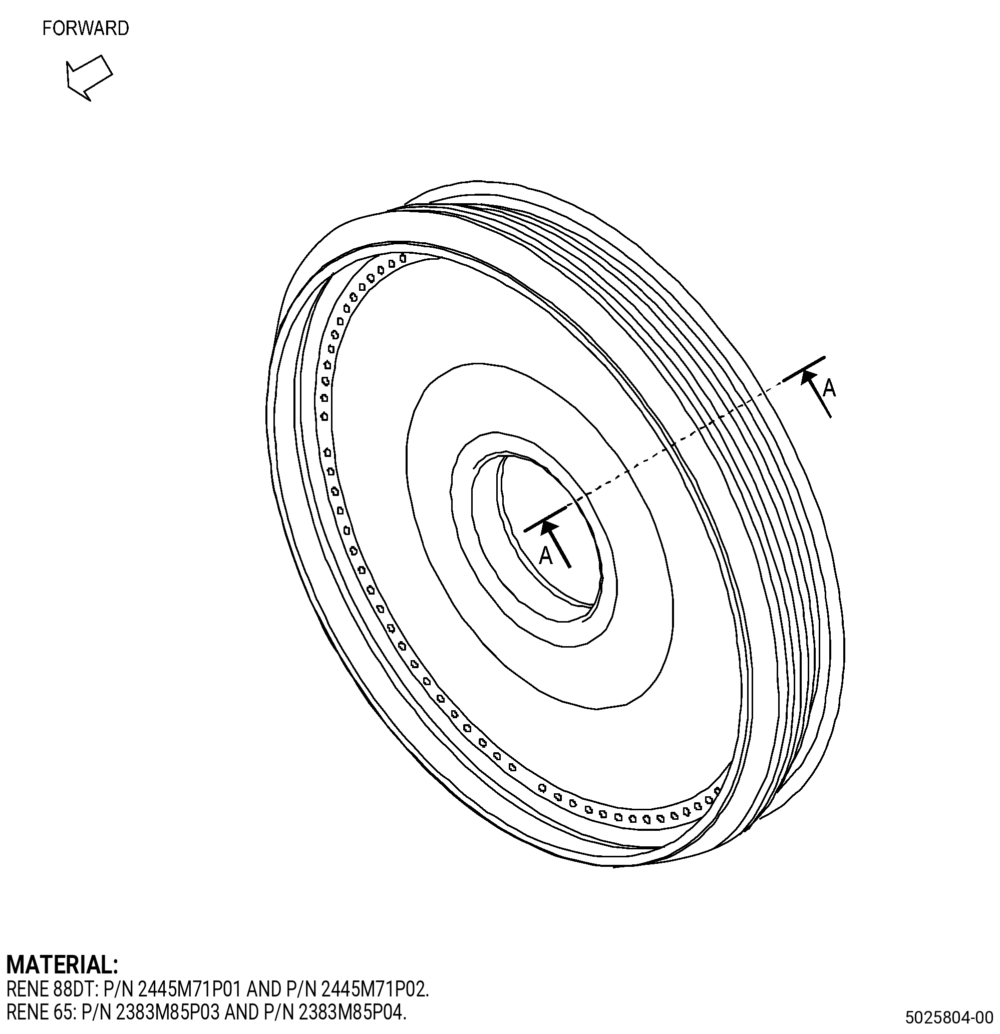
| HIGH PRESSURE TURBINE ROTOR INTERSTAGE SEAL - REPAIR - BLEND REPAIR OF THE SEAL | ||
| GENX-1B CLEANING,INSPECTION,AND REPAIR MANUAL | Dated: 09/27/2021 | |
| CIR 72-53-43 , REPAIR 004 | ||
| HIGH PRESSURE TURBINE ROTOR INTERSTAGE SEAL - REPAIR - BLEND REPAIR OF THE SEAL | ||
| * * * FOR ALL |
| TASK 72-53-43-300-804 |
| 1 . | Blend Repair of the Seal. |
| A. | This procedure gives instructions to repair the high pressure turbine rotor interstage seal (seal) by blending. Refer to Figure 901. |
| B. | The following maximum repairable limits apply to this repair: |
| NOTE: |
|
| NOTE: |
|
| (4) | Visual Inspection. |
| (d) | Do an inspection of the seal bore, bore edge radius, and hub faces for: |
| 1 | Scratches: |
| Maximum repairable limit: |
|
| 2 | Nicks and dents: |
| Maximum repairable limit: |
|
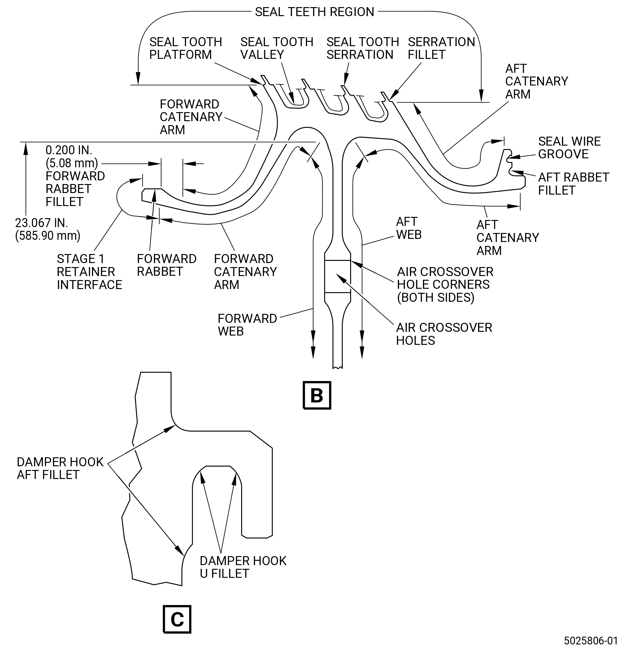
| (e) | Do an inspection of the seal teeth region for: |
| 2 | Nicks, scratches, or dents on 1st tooth (forward tooth): |
| Maximum repairable limit: |
|
| 4 | Bending of serrations on 1st tooth (forward tooth): |
| Maximum repairable limit: |
|
| (f) | Do an inspection of the ID bayonet for: |
| 1 | Nicks, dents, scratches, or other damage (do not include ID bayonet groove): |
| Maximum repairable limit: |
|
| 4 | Nicks, dents, and scratches, fretting or other damage in ID bayonet groove, with 0.262 inch (6.65 mm) distance from retaining wire assembly slot corner. Refer to Figure 801 and as follows: |
| Maximum repairable limit: |
|
| (g) | Do an inspection of the forward web and aft web, do not include the air crossover holes and hole corners, for: |
| 1 | Nicks, dents, scratches, or other damage: |
| Maximum repairable limit: |
|
| (i) | Do an inspection of the aft damper rail, but do not include the damper hook aft fillets and the damper hook U fillet, for: |
| 1 | Nicks and scratches: |
| Maximum repairable limit: |
|
| 2 | Dents: |
| Maximum repairable limit: |
|
| (l) | Do an inspection of the forward and aft catenary arms for: |
| 1 | Nicks, dents, scratches, or other damage: |
| Maximum repairable limit: |
|
| (n) | Do an inspection of the lip next to the aft rabbet. Refer to Figure 801 and as follows: |
| 1 | Nicks, dents, scratches, or other damage: |
| Maximum repairable limit: |
|
| C. | The subsequent table gives a list of the part numbers that are applicable to this repair. All part numbers are applicable to all paragraphs unless specified differently. |
|
|||||||||||||||||||||||
| D. | Proprietary/Complex Process Statement. |
| (1) | None. |
| 2 . | Tools, Equipment, and Materials. |
| NOTE: |
|
| A. | Tools and Equipment. |
| (1) | Special Tools. None. |
| (2) | Standard Tools and Equipment. None. |
| (3) | Locally Manufactured Tools. None. |
| B. | Consumable Materials. |
|
| C. | Referenced Procedures. |
| D. | Expendable Parts. None. |
| E. | SPD Information. |
| (1) | Locally Manufactured SPD. None. |
| F. | Special Solutions. None. |
| G. | Test Specimens. None. |
| 3 . | Dimensional Information. |
| Subtask 72-53-43-220-110 |
| A. | Refer to Figure 901 and Figure 902 for specified dimensions and locations. |
| NOTE: |
|
| NOTE: |
|
| 4 . | Setup Information. |
| None. |
| 5 . | Procedure. |
| Subtask 72-53-43-350-028 |
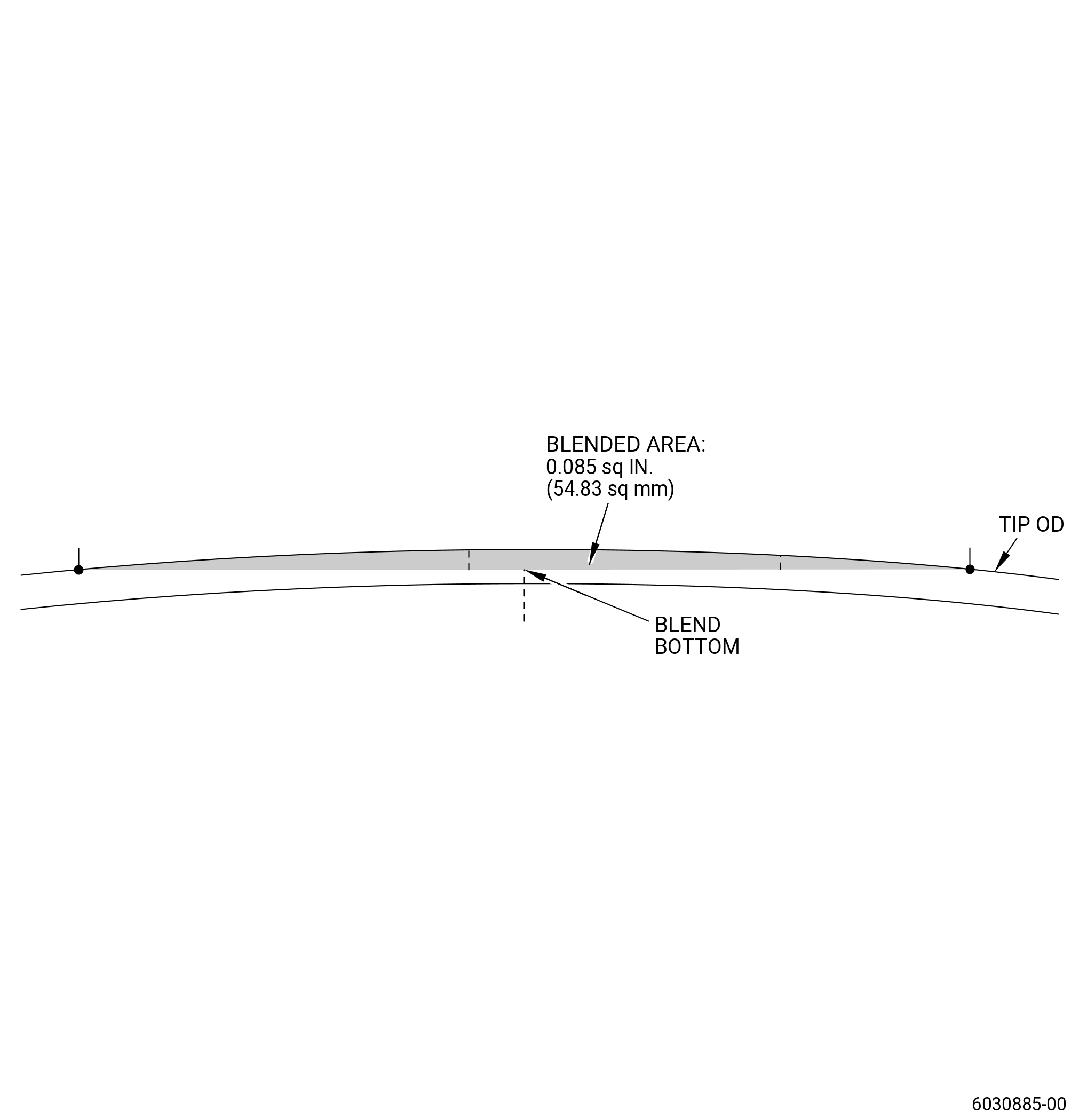
| A. | Blend the repairable areas of the seal. Refer to TASK 70-42-00-350-002 (BLENDING AND REMOVAL OF HIGH METAL PROCEDURES) and as follows: |
| (1) | Do not blend the areas of the seal with pitting, fretting, or wear. |
| (2) | Blend using limits contained in visual inspection area of this repair. |
| Subtask 72-53-43-110-011 |
| B. | Etch the seal repair areas. Refer to TASK 70-24-00-110-033 (ETCHING PROCEDURES FOR FLUORESCENT-PENETRANT INSPECTION), TASK 70-24-01-110-034 (SWAB ETCHING PROCEDURE), and as follows: |
| (1) | Use Class C or Class G etchant. |
| Subtask 72-53-43-230-007 |
| C. | Alternative Procedure Available. Do an inspection of the seal repair areas. Refer to TASK 70-32-00-200-002 (INDIRECT INSPECTION METHODS), TASK 70-32-02-230-001 (FLUORESCENT PENETRANT INSPECTION), Figure 902, and as follows: |
| (1) | Use Class G penetrant. |
| (2) | Refer to TASK 72-53-43-200-806 (72-53-43, INSPECTION 001, CONFIG 02), for reject limits/criteria. |
| Subtask 72-53-43-230-008 |
| C.A. | Alternative Procedure. Do an inspection of the seal repair areas. Refer to TASK 70-32-00-200-002 (INDIRECT INSPECTION METHODS), TASK 70-32-03-230-002 (SPOT-FLUORESCENT-PENETRANT INSPECTION), Figure 902, and as follows: |
| (1) | Use Class G penetrant. |
| (2) | Refer to TASK 72-53-43-200-806 (72-53-43, INSPECTION 001, CONFIG 02), for reject limits/criteria. |
| Subtask 72-53-43-350-029 |
| WARNING: |
|
| D. | Use a C10-010 Scotch Brite pad to remove the effects of the swab etching procedure in the seal repair areas. |
| Subtask 72-53-43-380-002 |
| E. | Peen the seal repair areas. Refer to TASK 70-47-01-380-016 (SHOTPEENING) and as follows: |
| (1) | Apply C10-021 plastic tape to the areas of the seal with thermal spray coating. |
| (2) | Use C04-166 CCW14 steel shot. |
| (3) | Use C10-205 type N Almen strips. |
| (a) | Use a simple or simulative fixture for saturation curve generation and intensity verification. |
| (4) | Peen the seal to an intensity of 0.006-0.012N. |
| (5) | Overspray is permitted out of areas with masking. |
| (6) | 125 percent coverage is necessary. |
| Subtask 72-53-43-350-030 |
| F. | Remove all masking from the seal. |
| Subtask 72-53-43-160-006 |
| G. | Clean the repair areas of the seal. Refer to TASK 70-21-00-110-051 (CHEMICAL CLEANING), TASK 70-21-03-160-001 (CLEANING METHOD NO. 3 - STEAM CLEANING). |
| Subtask 72-53-43-220-111 |
| H. | Do a final inspection of the seal blended areas. Refer to TASK 72-53-43-200-806 (72-53-43, INSPECTION 001, CONFIG 02). |