| GENX-1B CLEANING,INSPECTION,AND REPAIR MANUAL | Dated: 11/18/2021 | |
| CIR 72-53-43 , INSPECTION 001 | ||
| HPT ROTOR INTERSTAGE SEAL - INSPECTION 001 - CONFIGURATION 02 | ||
| GENX-1B CLEANING,INSPECTION,AND REPAIR MANUAL | Dated: 11/18/2021 | |
| CIR 72-53-43 , INSPECTION 001 | ||
| HPT ROTOR INTERSTAGE SEAL - INSPECTION 001 - CONFIGURATION 02 | ||
| * * * FOR ALL PIP 2 |
| TASK 72-53-43-200-806 |
| 1 . | General. |
| A. | This procedure gives instructions to do an inspection of the HPT rotor interstage seal (interstage seal): |
| • |
|
| B. | There are two configurations for the interstage seal: |
| (1) | Configuration 1 interstage seal does not have a corrosion resistant coating on the outer rim surfaces of the seal. |
| (2) | Configuration 2 interstage seal has a corrosion resistant coating on the outer rim surfaces of the interstage seal. |
| (3) | For both configurations, refer to area CW in Figure 801. |
| 2 . | Tools, Equipment, and Materials. |
| NOTE: |
|
| A. | Tools and Equipment. |
| (1) | Special Tools. None. |
| (2) | Standard Tools and Equipment. |
| (3) | Locally Manufactured Tools. None. |
| B. | Consumable Materials. |
|
| C. | Referenced Procedures. |
|
| D. | Expendable Parts. None. |
| 3 . | Specific Inspection Procedure. |
| NOTE: |
|
| Subtask 72-53-43-350-024 |
| A. | Remove the coating from the seal serrations of the interstage seal (diameter AW1, diameter AW2, diameter AW3, and diameter AW4). Refer to TASK 72-53-43-300-801 (72-53-43, REPAIR 001) or TASK 72-53-43-300-805 (72-53-43, REPAIR 005). |
| Subtask 72-53-43-350-025 |
| B. | For configuration 2 parts only, remove the corrosion resistant coating from area CW of the interstage seal. Refer to TASK 72-53-43-300-802 (72-53-43, REPAIR 003). |
| Subtask 72-53-43-230-004 |
| C. | Do a Class G fluorescent penetrant inspection of the interstage seal. Refer to TASK 70-32-02-230-001 (FLUORESCENT PENETRANT INSPECTION) and do as follows: |
| (1) | Apply non-aqueous wet developer (NAWD) to the air crossover hole to air crossover pad radii. |
| (2) | Indications more than 0.015 inch (0.38 mm) are not permitted. |
| (3) | Carefully examine the areas that follow because they are the most important. Refer to Figure 801. |
| • |
|
| • |
|
| • |
|
| • |
|
| • |
|
| • |
|
| • |
|
| Subtask 72-53-43-250-007 |
| D. | Do an eddy current inspection of the interstage seal bore as follows: |
| Subtask 72-53-43-160-004 |
| CAUTION: |
|
| (1) | Make sure that the interstage seal is clean. Refer to TASK 72-53-43-100-801 (72-53-43, REPAIR 001). |
| Subtask 72-53-43-250-008 |
| (2) | Do an eddy current inspection of the bore surfaces. Refer to TASK 70-32-10-250-003 (2 MHZ EDDY CURRENT INSPECTION OF BORES IN ROTATING ENGINE HARDWARE USING SYSTEMS UNDER COMPUTER, NUMERIC, OR ROBOTIC CONTROL) and Figure 802. |
| NOTE: |
|
| (a) | Changing the equipment or the procedure specified in this inspection can have an unwanted effect on the inspection results. Before changing the equipment or the procedure, write to: |
| GE Aircraft Engines, OTC |
| One Neumann Way, MD: Q8 |
| Cincinnati, Ohio 45215 |
| USA |
| (b) | The materials are Rene 88 for interstage seals (02-170B , 72-53-00) (SIN 150B3) and (02-170C , 72-53-00) (SIN 150B3) and Rene 65 for interstage seals (02-170 , 72-53-00) (SIN 150B3) and (02-170A , 72-53-00) (SIN 150B3). Use correction factors for calibration as necessary. Refer to TASK 70-32-10-250-003 (2 MHZ EDDY CURRENT INSPECTION OF BORES IN ROTATING ENGINE HARDWARE USING SYSTEMS UNDER COMPUTER, NUMERIC, OR ROBOTIC CONTROL). |
| (c) | Use the GE-FQAP-428inspection kit to do an inspection of the bore zones shown in Figure 802. |
| (d) | Examine the inspection results. Use the limits that follow: |
| 1 | The eddy current inspection limit is 1500 mV. |
| 2 | If the amplitude of an indication is more than 1500 mV, the fan disk is not serviceable. |
| (e) | Complete the eddy current data sheets. |
| (f) | Make sure to complete all records during the eddy current inspection. Keep all records made during the inspection. |
| Subtask 72-53-43-220-117 |
| E. | Do a focused inspection of the air crossover holes of the interstage seal. Refer to TASK 72-53-43-800-801 (72-53-43, SPECIAL PROCEDURES 001). |
| 4 . | Visual Inspection. |
| Refer to Figure 801. |
| Subtask 72-53-43-220-120 |
| A. | Visual inspection serviceable limits for fretting are not applicable to HPT rotor interstage seal P/N 2383M85P04 with part serial numbers listed in GEnx-1B SB 72-0484 Table 6 and Table 7. |
| Subtask 72-53-43-220-121 |
| B. | Visual inspection serviceable limits for nicks, dents, scratches, fretting, are not applicable to HPT rotor interstage seal P/N 2383M85P04 with part serial numbers listed in GEnx-1B SB 72-0484 Table 8. |
| Subtask 72-53-43-220-081 |
| C. | Do an inspection of all areas of the interstage seal for: |
| (1) | Cracks: |
| Maximum serviceable limit: |
|
| Repair method: |
|
| Subtask 72-53-43-220-082 |
| D. | Do an inspection of the seal bore, bore edge radius, and hub faces for: |
| NOTE: |
|
| (1) | Scratches: |
| Maximum serviceable limit: |
|
| Repair method: |
|
| Subtask 72-53-43-220-083 |
| (2) | Nicks and dents: |
| Maximum serviceable limit: |
|
| Repair method: |
|
| Subtask 72-53-43-220-084 |
| E. | Do an inspection of the seal teeth region for: |
| (1) | Wear on the tip: |
| Maximum serviceable limit: |
|
| Repair method: |
|
| Subtask 72-53-43-220-085 |
| (2) | Nicks, scratches, or dents on 1st tooth (forward tooth): |
| Maximum serviceable limit: |
|
| Repair method: |
|
| Subtask 72-53-43-220-086 |
| (3) | Cracks or cracked out areas: |
| Maximum serviceable limit: |
|
| Repair method: |
|
| Subtask 72-53-43-220-087 |
| (4) | Bending of serrations on 1st tooth (forward tooth): |
| Maximum serviceable limit: |
|
| Repair method: |
|
| Subtask 72-53-43-220-122 |
| (5) | Nicks, dents, or scratches on 2nd, 3rd, and 4th teeth: |
| Maximum serviceable limit: |
|
| Repair method: |
|
| Subtask 72-53-43-220-123 |
| (6) | Bending of 2nd, 3rd, and 4th teeth: |
| Maximum serviceable limit: |
|
| Repair method: |
|
| Subtask 72-53-43-220-088 |
| (7) | Wear on diameters AW1, AW2, AW3, and AW4: |
| Maximum serviceable limit: |
|
| Repair method: |
|
| Subtask 72-53-43-220-114 |
| (8) | Missing coating on the serration tip and on the face (after coating applied): |
| Minimum serviceable limit: |
|
| Repair method: |
|
| Subtask 72-53-43-220-089 |
| F. | Do an inspection of the ID bayonet, for: |
| (1) | Nicks, dents, scratches, or other damage (do not include ID bayonet groove): |
| Maximum serviceable limit: |
|
| Repair method: |
|
| Subtask 72-53-43-220-124 |
| (2) | Nicks, dents, and scratches, or other damage in ID bayonet groove (except within 0.262 inch (6.65 mm) distance from retaining wire slot assembly slot corner). Refer to Figure 801 and as follows: |
| Maximum serviceable limit (for interstage seal number 2383M85P04 with part serial numbers listed in GEnx-1B SB 72-0484 Table 8): |
|
| Maximum serviceable limit: |
|
| Repair method: |
|
| Subtask 72-53-43-220-125 |
| (3) | Fretting, or other damage in ID bayonet groove (except within 0.262 inch (6.65 mm) distance from retaining wire slot assembly slot corner). Refer to Figure 801 and as follows: |
| Maximum serviceable limit (for interstage seal number 2383M85P04 with part serial numbers listed in GEnx-1B SB 72-0484 Table 8): |
|
| Maximum serviceable limit: |
|
| Repair method: |
|
| Subtask 72-53-43-220-126 |
| (4) | Nicks, dents, and scratches, fretting or other damage in ID bayonet groove, within 0.262 inch (6.65 mm) distance from retaining wire assembly slot corner. Refer to Figure 801 and as follows: |
| Maximum serviceable limit: |
|
| Repair method: |
|
| Subtask 72-53-43-220-090 |
| G. | Do an inspection of the forward web and aft web, do not include the air crossover holes and hole corners, for: |
| NOTE: |
|
| (1) | Nicks, dents, scratches, or other damage: |
| Maximum serviceable limit: |
|
| Repair method: |
|
| Subtask 72-53-43-220-091 |
| H. | Do an inspection of the air crossover holes and hole corners (15 holes) for: |
| (1) | Nicks, dents, scratches, or other damage: |
| Maximum serviceable limit: |
|
| Repair method: |
|
| Subtask 72-53-43-220-092 |
| (2) | Damage at the edge radius: |
| Maximum serviceable limit: |
|
| Repair method: |
|
| Subtask 72-53-43-220-093 |
| I. | Do an inspection of the aft damper rail, but do not include the damper hook aft fillets and the damper hook U fillet, for: |
| NOTE: |
|
| (1) | Deleted. |
| Subtask 72-53-43-220-094 |
| (2) | Nicks and scratches: |
| Maximum serviceable limit: |
|
| Repair method: |
|
| Subtask 72-53-43-220-095 |
| (3) | Dents: |
| Maximum serviceable limit: |
|
| Repair method: |
|
| Subtask 72-53-43-220-096 |
| J. | Do an inspection of the aft rabbet for: |
| (1) | Fretting: |
| Maximum serviceable limit (for interstage seal part number 2383M85P04 with part serial numbers listed in GEnx-1B SB 72-0484): |
|
| Maximum serviceable limit (for part numbers 2383M85P03, 2383M85P04, and 2383M85P05): |
|
| Maximum serviceable limit (for part numbers 2445M71P01 and 2445M71P02): |
|
| Repair method: |
|
| Subtask 72-53-43-220-097 |
| (2) | Nicks, dents, and scratches: |
| Maximum serviceable limit (for interstage seal part number 2383M85P04 with part serial numbers listed in GEnx-1B SB 72-0484 Table 8): |
|
| Maximum serviceable limit: |
|
| Repair method: |
|
| Subtask 72-53-43-220-098 |
| K. | Do an inspection of the forward rabbet for: |
| (1) | Nicks, dents, and scratches: |
| Maximum serviceable limit (for interstage seal number 2383M85P04 with part serial numbers listed in GEnx-1B SB 72-0484 Table 8): |
|
| Maximum serviceable limit (for part numbers 2383M85P03, 2383M85P04, and 2383M85P05): |
|
| Maximum serviceable limit (for part numbers 2445M71P01 and 2445M71P02): |
|
| Subtask 72-53-43-220-101 |
| L. | Do an inspection of the forward and aft catenary arms for: |
| (1) | Nicks, dents, scratches, or other damage: |
| Maximum serviceable limit: |
|
| Repair method: |
|
| Subtask 72-53-43-220-113 |
| (2) | Localized pitting or isolated deposited material on the inner diameter. Refer to Figure 803. |
| Maximum serviceable limit: |
|
| Maximum repairable limit (for interstage seal part number 2383M85P04 with part serial numbers listed in GEnx-1B SB 72-0484): |
|
| Maximum repairable limit: |
|
| Repair method (for stage interstage seal part number 2383M85P04 with part serial numbers listed in GEnx-1B SB 72-0484): |
|
| Repair method: |
|
| • |
|
| • |
|
| • |
|
| Subtask 72-53-43-220-127 |
| M. | Do an inspection of the stage 1 retainer interface for: |
| (1) | Nicks, dents, and scratches: |
| Maximum serviceable limit (for interstage seal number 2383M85P04 with part serial numbers listed in GEnx-1B SB 72-0484 Table 8): |
|
| Maximum serviceable limit (for part numbers 2383M85P03, 2383M85P04, and 2383M85P05): |
|
| Maximum serviceable limit (for part numbers 2445M71P01 and 2445M71P02): |
|
| Subtask 72-53-43-220-128 |
| N. | Do an inspection of the lip next to the aft rabbet. Refer to Figure 801 and as follows: |
| (1) | Nicks, dents, scratches, or other damage: |
| Maximum serviceable limit: |
|
| Repair method: |
|
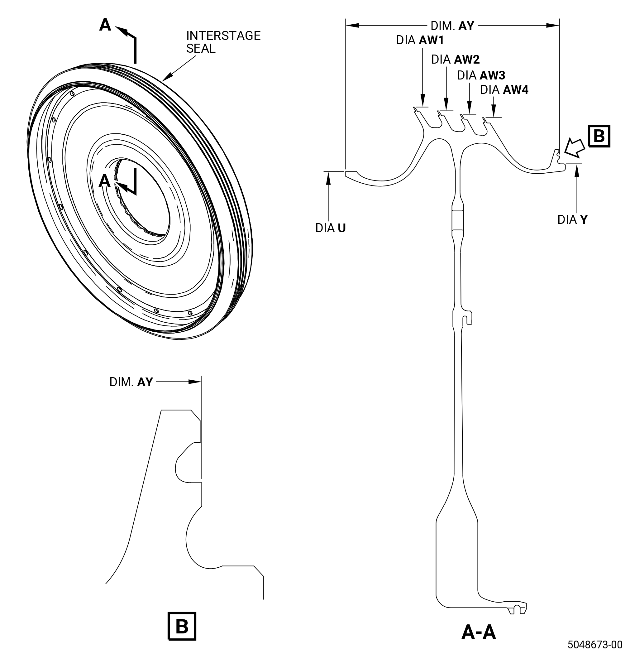
| 5 . | Dimensional Inspection. |
| Refer to Figure 804. |
| Subtask 72-53-43-220-102 |
| A. | Do an inspection of the interstage seal for: |
| (1) | Diameter U: |
| Minimum serviceable limit: |
|
| Maximum serviceable limit: |
|
| Repair method: |
|
| Subtask 72-53-43-220-103 |
| (2) | Dimension AY: |
| Minimum serviceable limit: |
|
| Maximum serviceable limit: |
|
| Repair method: |
|
| Subtask 72-53-43-220-104 |
| (3) | Diameter Y: |
| Minimum serviceable limit: |
|
| Maximum serviceable limit: |
|
| Repair method: |
|
| Subtask 72-53-43-220-105 |
| B. | Do an inspection of the seal serrations (AW1, AW2, AW3, AW4) as follows: |
| NOTE: |
|
| (1) | Diameter AW1: |
| Minimum serviceable limit: |
|
| Maximum serviceable limit: |
|
| Repair method: |
|
| Subtask 72-53-43-220-106 |
| (2) | Diameter AW2: |
| Minimum serviceable limit: |
|
| Maximum serviceable limit: |
|
| Repair method: |
|
| Subtask 72-53-43-220-107 |
| (3) | Diameter AW3: |
| Minimum serviceable limit: |
|
| Maximum serviceable limit: |
|
| Repair method: |
|
| Subtask 72-53-43-220-108 |
| (4) | Diameter AW4: |
| Minimum serviceable limit: |
|
| Maximum serviceable limit: |
|
| Repair method: |
|
| 6 . | Post Inspection Procedure. |
| Subtask 72-53-43-380-005 |
| A. | Shot peen the surfaces in the marked zones for the interstage seal (02-170B , 72-53-00) (SIN 150B3) and (02-170C , 72-53-00) (SIN 150B3). Refer to Figure 805, TASK 70-47-01-380-016 (SHOTPEENING), and as follows: |
| (1) | Mask all the area that will not peen as follows: |
| (a) | Use C10-021 masking tape or an applicable equivalent as necessary. |
| (2) | Use C04-166 conditioned cut wire. |
| (3) | Shot peen to an intensity of 6-12N. |
| (4) | Use C10-205 test strips. |
| (5) | A minimum coverage of 125 percent is necessary. |
| (6) | Remove all the masking tape. |
| Subtask 72-53-43-350-026 |
| B. | Apply the coating to the seal serrations. Refer to TASK 72-53-43-300-801 (72-53-43, REPAIR 001) or TASK 72-53-43-300-805 (72-53-43, REPAIR 005). |
| Subtask 72-53-43-350-027 |
| C. | For configuration 2 parts only, apply the corrosion resistant coating to area CW. Refer to Figure 801 and TASK 72-53-43-300-802 (72-53-43, REPAIR 003). |