| GENX-1B CLEANING,INSPECTION,AND REPAIR MANUAL | Dated: 01/08/2025 | |
| CIR 72-53-43 , REPAIR 001 | ||
| HIGH PRESSURE TURBINE ROTOR INTERSTAGE SEAL - REPAIR - THERMAL SPRAY REPAIR OF THE SEAL TEETH COATING | ||
| GENX-1B CLEANING,INSPECTION,AND REPAIR MANUAL | Dated: 01/08/2025 | |
| CIR 72-53-43 , REPAIR 001 | ||
| HIGH PRESSURE TURBINE ROTOR INTERSTAGE SEAL - REPAIR - THERMAL SPRAY REPAIR OF THE SEAL TEETH COATING | ||
| * * * FOR ALL |
| TASK 72-53-43-300-801 |
| 1 . | Thermal Spray Repair of the Seal Teeth Coating. |
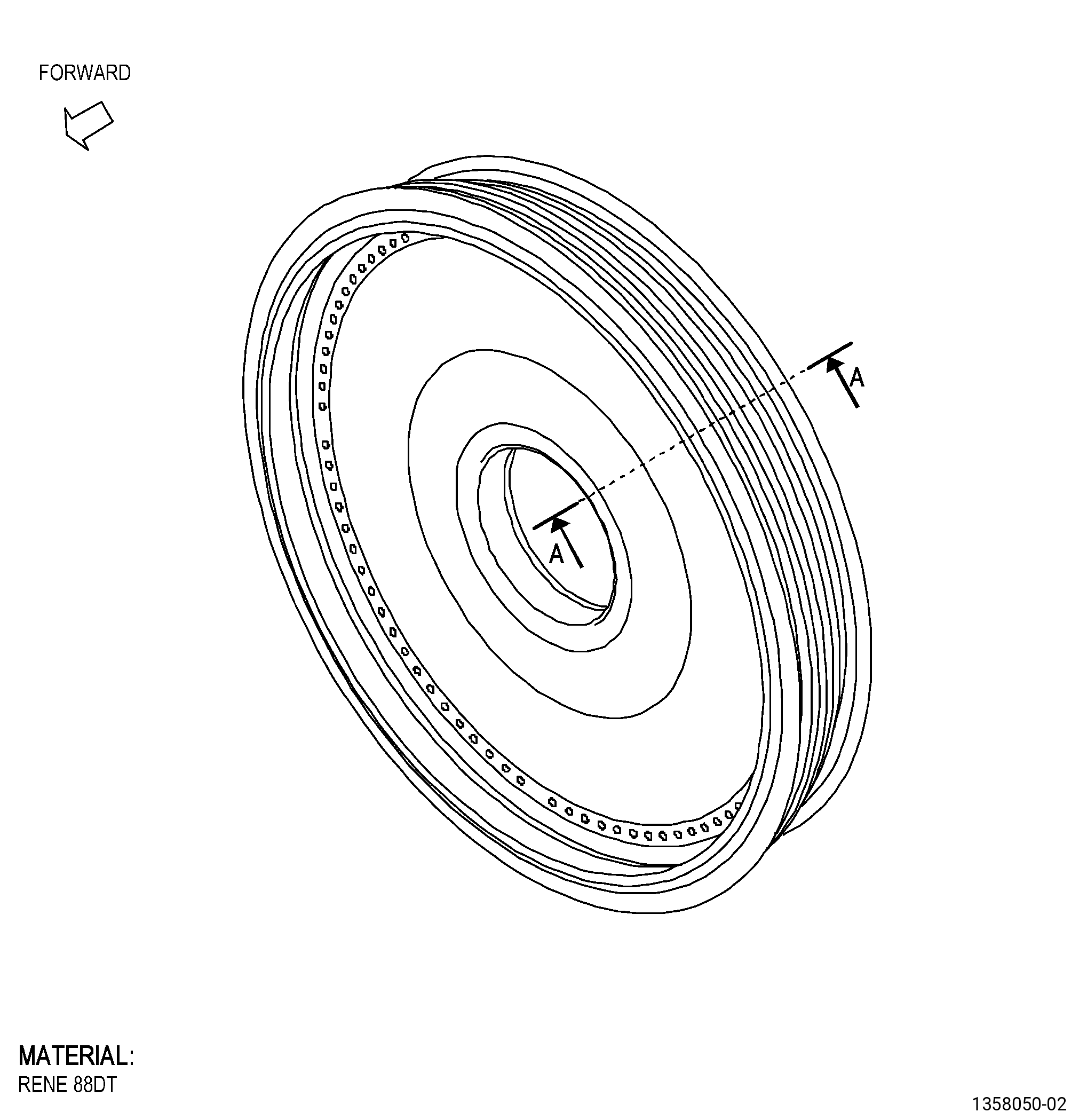
| A. | This procedure gives instructions to repair the HPT rotor interstage seal (seal) by removing and replacing the thermal spray coating on the seal teeth. Refer to Figure 901. |
| B. | The following maximum repairable limits apply to this repair: |
| NOTE: |
|
| NOTE: |
|
| (5) | Dimensional Inspection. |
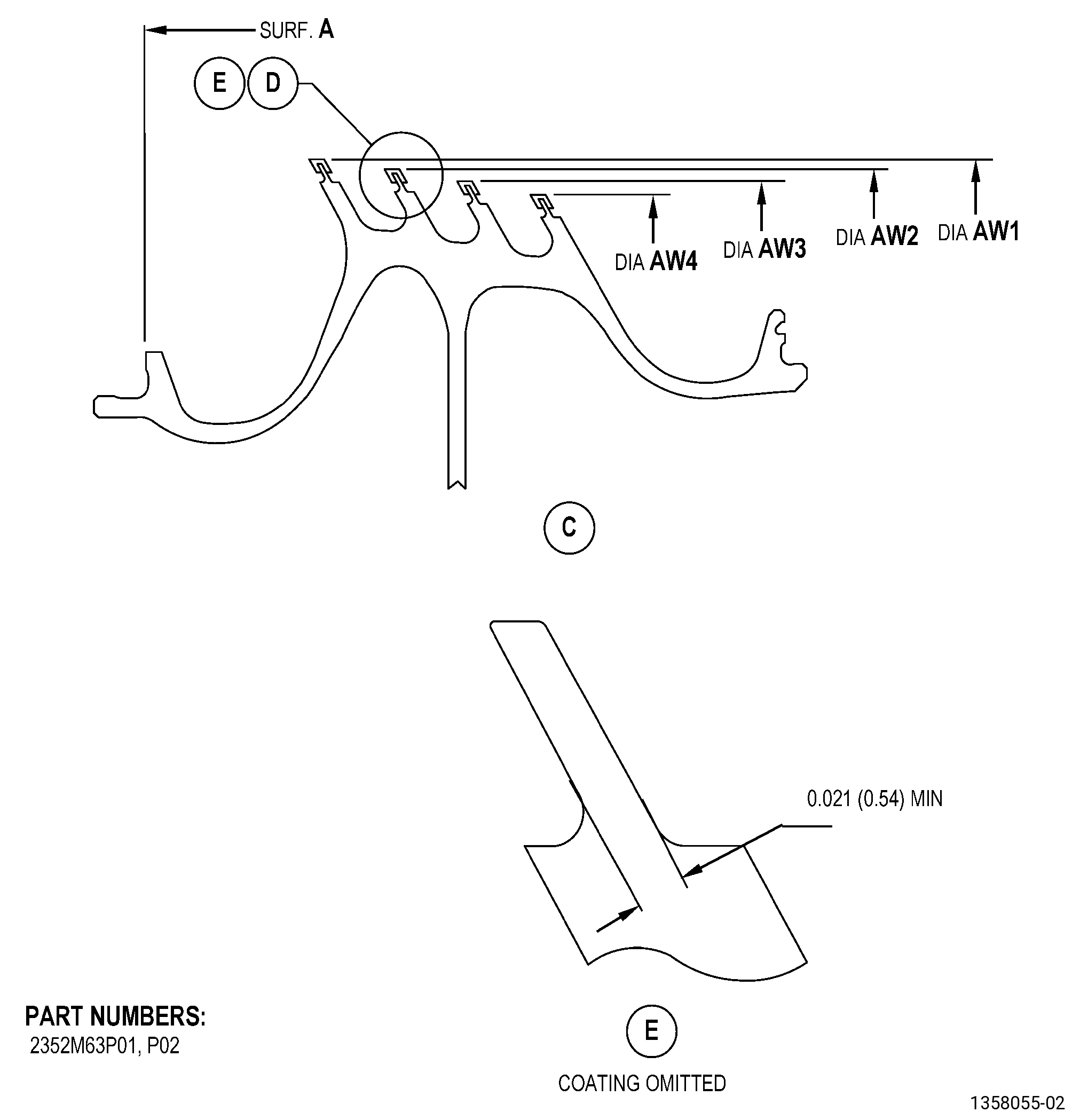
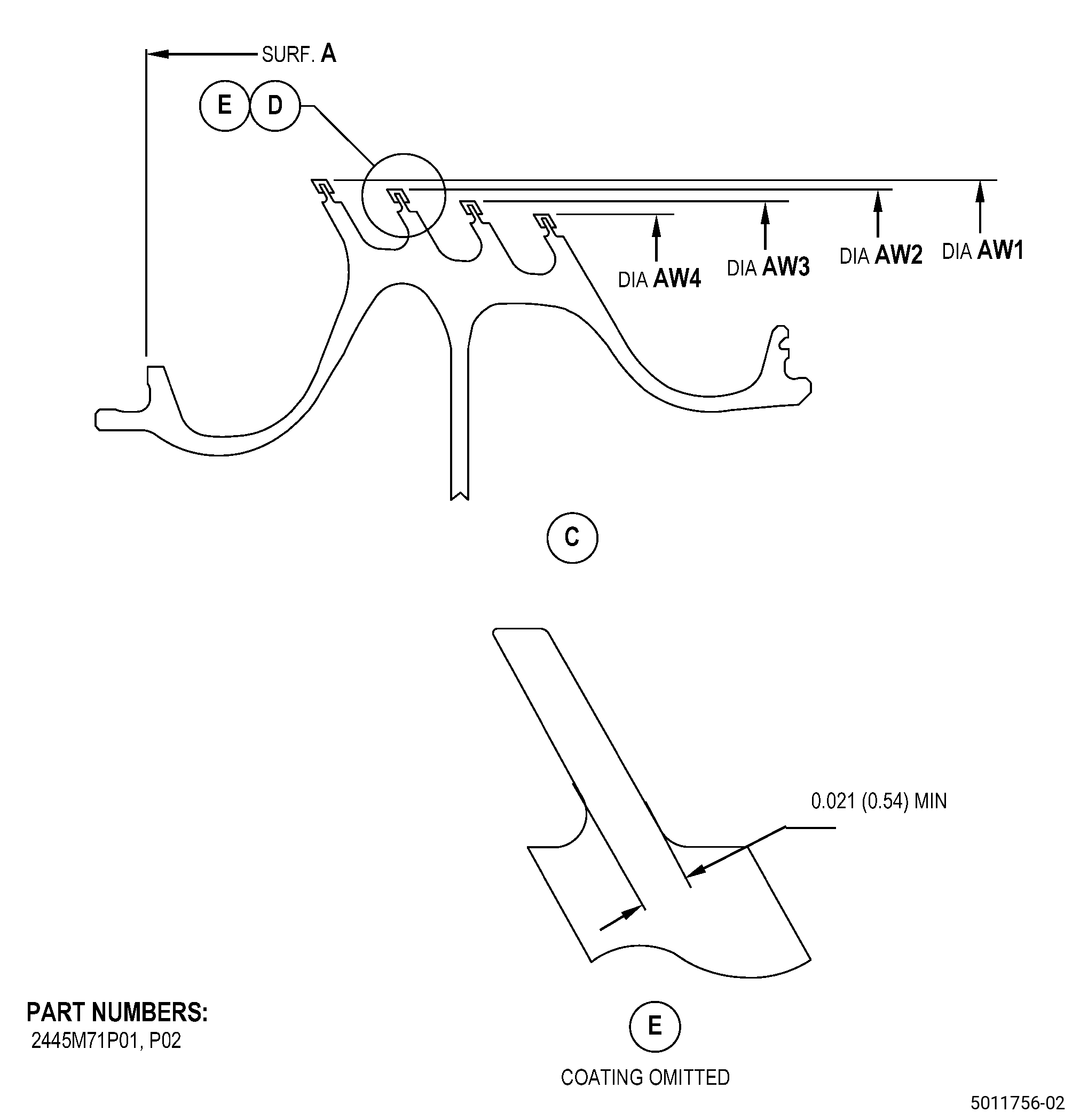
| (b) | Do an inspection of the seal serrations (AW1, AW2, AW3, AW4) as follows: |
| 1 | Diameter AW1: |
| Maximum repairable limit: |
|
| 2 | Diameter AW2: |
| Maximum repairable limit: |
|
| 3 | Diameter AW3: |
| Maximum repairable limit: |
|
| 4 | Diameter AW4: |
| Maximum repairable limit: |
|
| C. | The subsequent table gives a list of the part numbers that are applicable to this repair. All part numbers are applicable to all paragraphs unless specified differently. |
|
|||||||||||||||||||||||
| D. | Proprietary/Complex Process Statement. |
| (1) | None. |
| 2 . | Tools, Equipment, and Materials. |
| NOTE: |
|
| A. | Tools and Equipment. |
| (1) | Special Tools. None. |
| (2) | Standard Tools and Equipment. None. |
| (3) | Locally Manufactured Tools. |
|
| B. | Consumable Materials. |
|
| C. | Referenced Procedures. |
| D. | Expendable Parts. None. |
| E. | SPD Information. |
| (1) | Locally Manufactured SPD. None. |
| F. | Special Solutions. None. |
| G. | Test Specimens. Refer to TASK 70-49-02-340-003 (THERMAL SPRAYING ALUMINUM OXIDE - ALUMINA (POWDER)) and TASK 70-49-35-340-037 (THERMAL BARRIER COATING SYSTEM - YTTRIUM OXIDE STABILIZED ZIRCONIUM OXIDE (8% YTTRIUM OXIDE) OVER NICKEL CHROMIUM ALUMINUM YTTRIUM BONDCOAT) . |
| 3 . | Dimensional Information. |
| Subtask 72-53-43-220-049 |
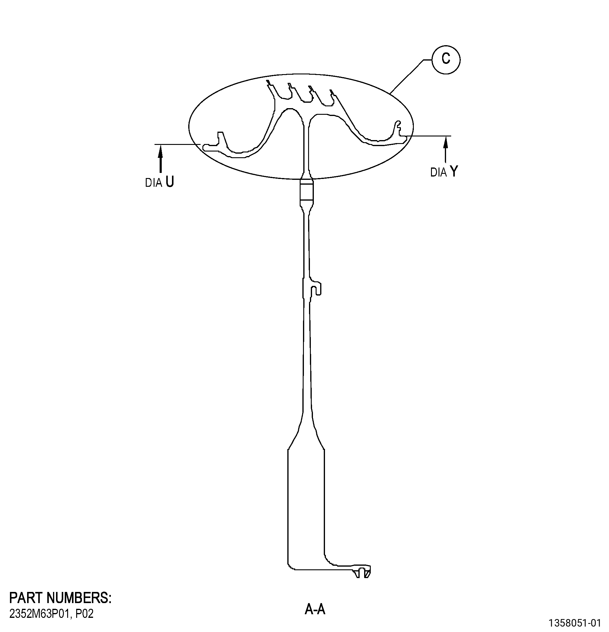
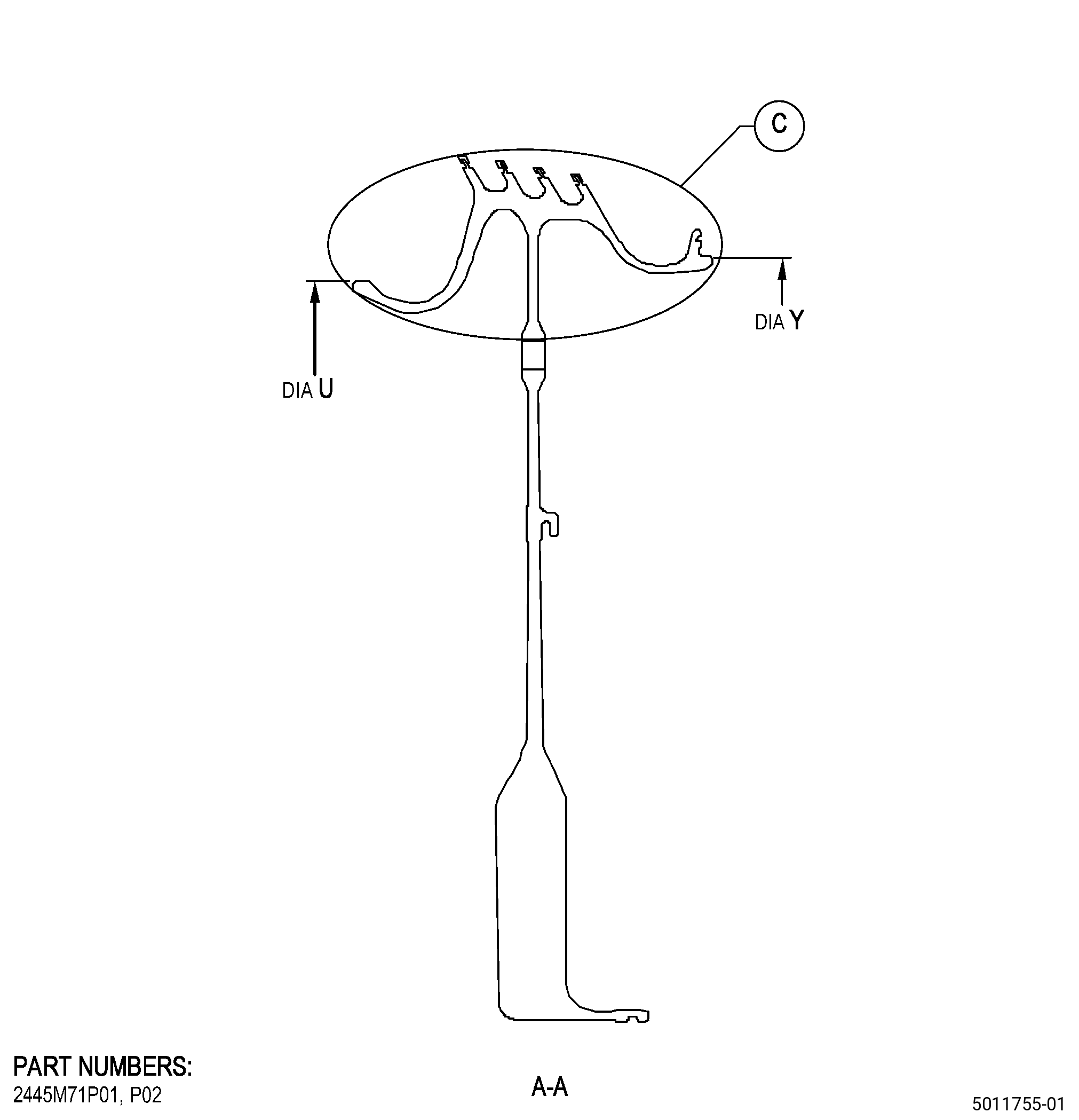
| A. | Refer to Figure 901 for specified dimensions and locations. |
| NOTE: |
|
| NOTE: |
|
|
| 4 . | Setup Information. |
| Subtask 72-53-43-350-005 |
| A. | Set-up the seal to machine the seal teeth as follows: |
| Subtask 72-53-43-930-001 |
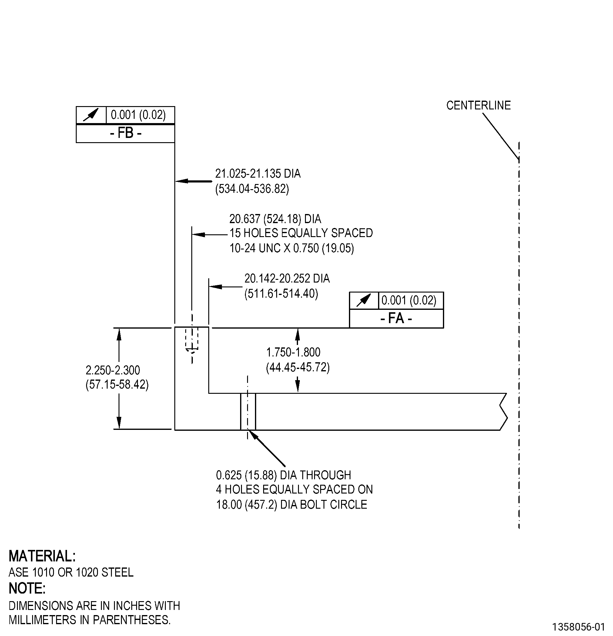
| (1) | If necessary, make the holding fixture. Refer to Figure 902. |
| Subtask 72-53-43-350-008 |
| (2) | Put the holding fixture on the machine turntable as follows: |
| (a) | Surface FA of the holding fixture must be flat to a maximum of 0.001 inch (0.02 mm) FIR. |
| (b) | Attach the holding fixture to the machine turntable. |
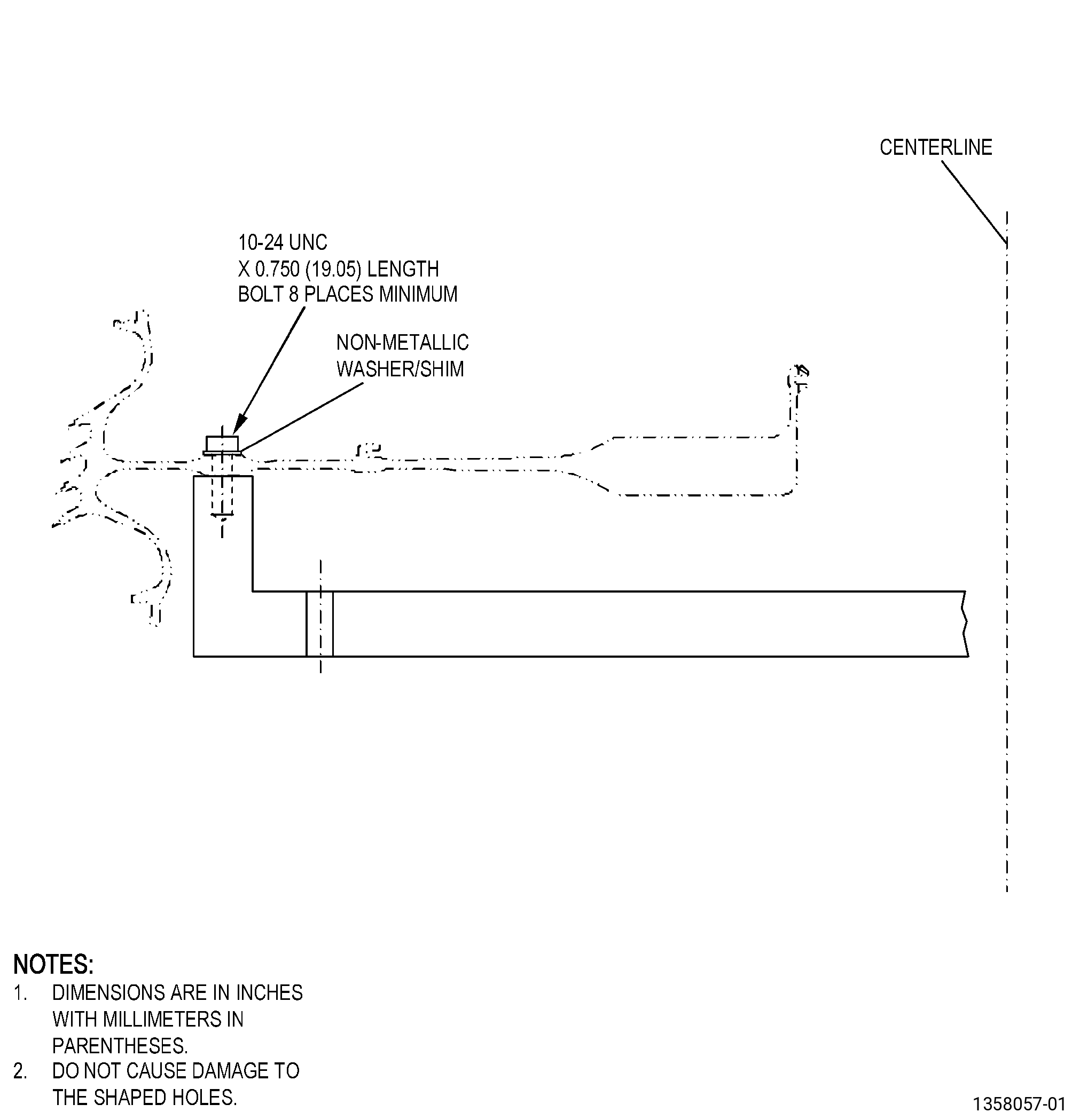
| (3) | Install the seal on the holding fixture. Refer to Figure 903 and as follows: |
| (a) | Diameter U must be concentric to the machine turntable centerline to a maximum of 0.001 inch (0.02 mm). |
| (b) | Surface A must be parallel to the machine turntable face to a maximum of 0.001 inch (0.02 mm). |
| 5 . | Procedure. |
| Subtask 72-53-43-110-010 |
| A. | Remove the thermal spray coating on the seal teeth. Refer to TASK 70-23-00-100-001 (STRIPPING PROCEDURES) and as follows: |
| (1) | Alternative Procedure Available. Refer to TASK 70-23-28-110-801 (STRIPPING THERMAL SPRAYED ALUMINUM OXIDE/NICKEL CHROME ALUMINUM YTTRIUM THERMAL SPRAY SEAL TEETH COATING ON RENE 88DT PARTS). |
| Subtask 72-53-43-350-007 |
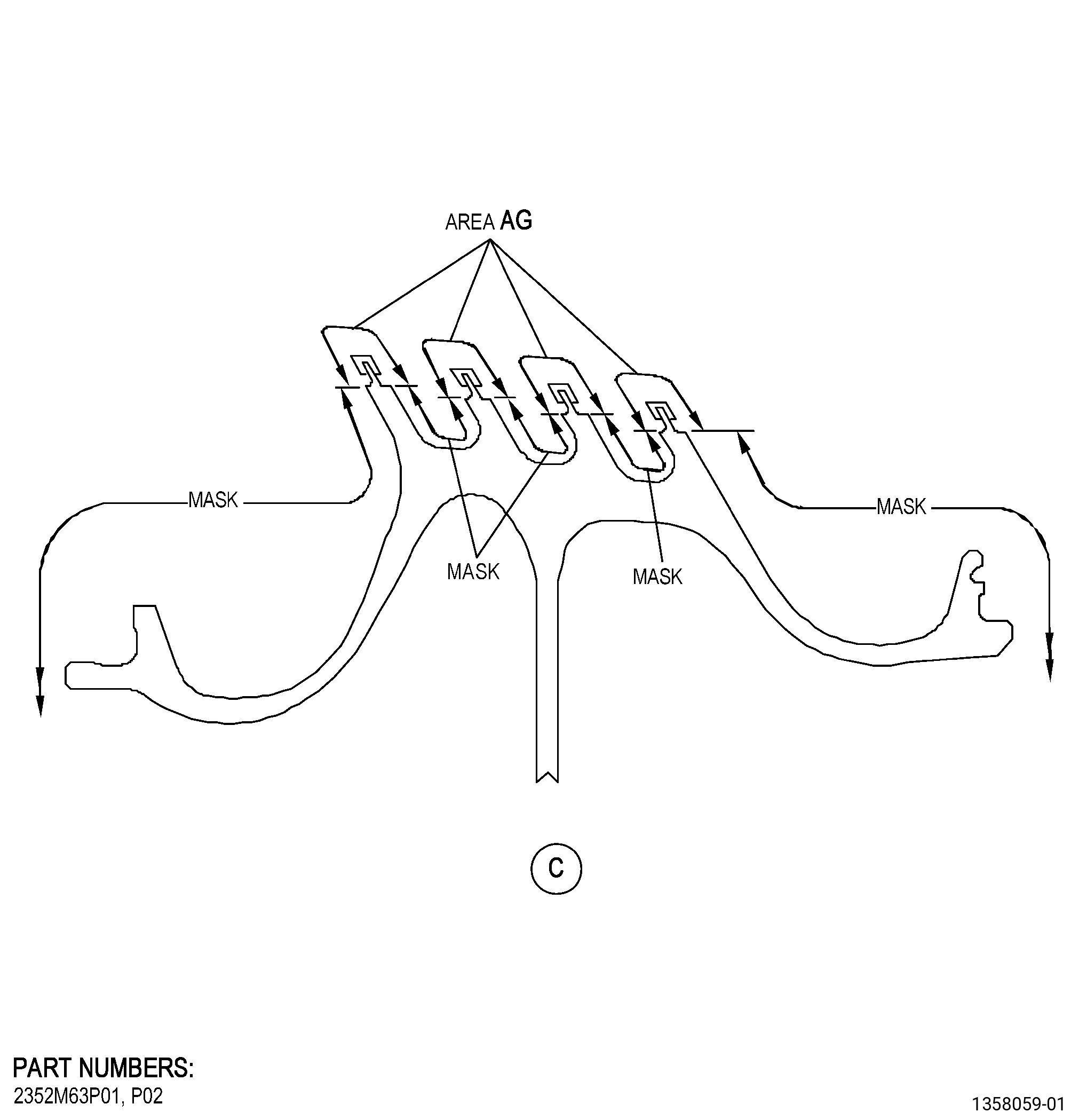
| (a) | Apply C10-012 masking tape or C10-021 duct tape to the seal teeth areas that you will not grit-blast. Refer to Figure 904. |
| Subtask 72-53-43-140-001 |
| (b) | Grit-blast the seal teeth to remove the top coating. |
| NOTE: |
|
| Subtask 72-53-43-350-009 |
| (c) | Remove the tape from the seal. |
| (d) | Remove the bond coating with the stripping solution. |
| Subtask 72-53-43-330-001 |
| (4).A. | Alternative Procedure. Refer to TASK 70-23-23-330-008 (REMOVAL OF COATINGS BY HIGH PRESSURE WATER STRIPPING). |
| Subtask 72-53-43-110-005 |
| B. | Etch the seal teeth. Refer to TASK 70-24-00-110-033 (ETCHING PROCEDURES FOR FLUORESCENT-PENETRANT INSPECTION), TASK 70-24-01-110-034 (SWAB ETCHING PROCEDURE), and as follows: |
| (1) | Use Class C etchant or Class G etchant. |
| Subtask 72-53-43-230-005 |
| C. | Alternate Procedure Available. Do an inspection of the seal teeth. Refer to TASK 70-32-00-200-002 (INDIRECT INSPECTION METHODS), TASK 70-32-02-230-001 (FLUORESCENT PENETRANT INSPECTION), and as follows: |
| (1) | Use Class G penetrant. |
| (2) | Refer to TASK 72-53-43-200-801 (72-53-43, INSPECTION 001, CONFIG 01) or TASK 72-53-43-200-806 (72-53-43, INSPECTION 001, CONFIG 02) for the fluorescent-penetrant inspection limits. |
| Subtask 72-53-43-230-006 |
| C.A. | Alternative Procedure. Do an inspection of the seal teeth. Refer to TASK 70-32-00-200-002 (INDIRECT INSPECTION METHODS), TASK 70-32-03-230-002 (SPOT-FLUORESCENT-PENETRANT INSPECTION), and as follows: |
| (1) | Use Class G penetrant. |
| (2) | Refer to TASK 72-53-43-200-801 (72-53-43, INSPECTION 001, CONFIG 01) or TASK 72-53-43-200-806 (72-53-43, INSPECTION 001, CONFIG 02) for the fluorescent-penetrant inspection limits. |
| Subtask 72-53-43-160-005 |
| D. | Clean the seal. Refer to TASK 70-21-00-110-051 (CHEMICAL CLEANING) and TASK 70-21-03-160-001 (CLEANING METHOD NO. 3 - STEAM CLEANING). |
| Subtask 72-53-43-220-050 |
| E. | Do a dimensional inspection of the seal diameter AW1, diameter AW2, diameter AW3, and diameter AW4. Refer to Subtask 72-53-43-220-049 (paragraph 3.A.), Figure 901, and as follows: |
| (1) | If diameter AW1, diameter AW2, diameter AW3, and/or diameter AW4 are less than the minimum in-process dimensions specified in Subtask 72-53-43-220-049 (paragraph 3.A.), you cannot repair the seal with this procedure. |
| Subtask 72-53-43-380-003 |
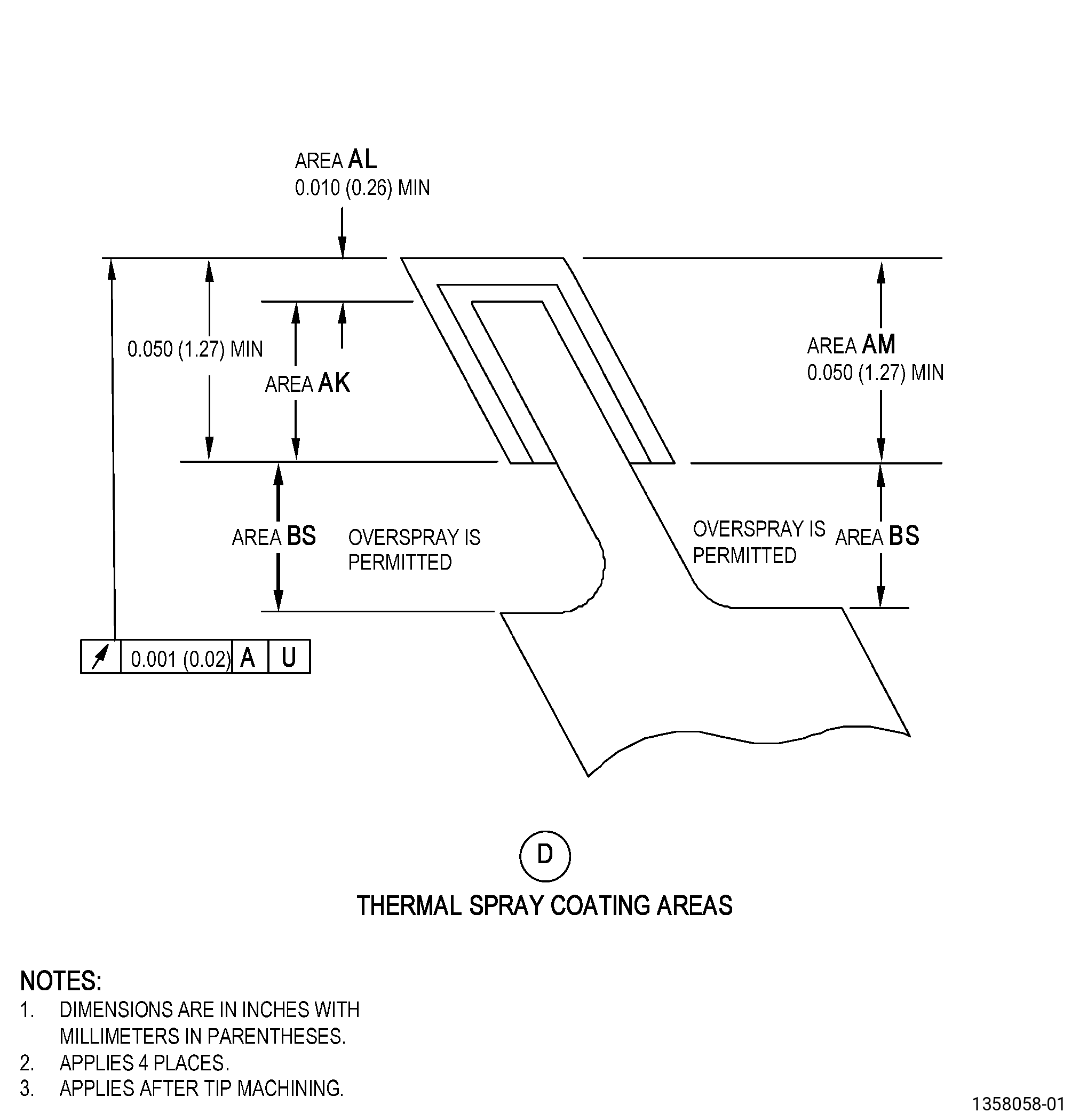
| F. | Peen the area AG of the seal. Refer to TASK 70-47-01-380-016 (SHOTPEENING), Figure 904, and do as follows: |
| (1) | Apply C10-021 plastic tape to areas that have thermal spray coating. |
| (2) | Use C04-166 CCW14 shot. |
| (3) | Peen to an intensity of 0.006-0.0012 N. |
| (4) | Direct impingement required. |
| (5) | Overspray is permitted. |
| (6) | The coverage must be a minimum of 125 percent. |
| (7) | Intensity verification is required by using a simulative fixture. |
| (8) | Remove all plastic tape from the part. |
| Subtask 72-53-43-340-001 |
| WARNING: |
|
| G. | Thermal-spray the seal teeth and the test specimens. Refer to TASK 70-49-00-340-001 (THERMAL SPRAYING), TASK 70-49-35-340-037 (THERMAL BARRIER COATING SYSTEM - YTTRIUM OXIDE STABILIZED ZIRCONIUM OXIDE (8% YTTRIUM OXIDE) OVER NICKEL CHROMIUM ALUMINUM YTTRIUM BONDCOAT), Figure 904, and as follows: |
| (1) | Apply C10-012 masking tape to the seal areas that you will not thermal-spray. |
| (2) | Prepare the seal teeth and the test specimens for thermal spraying as specified in TASK 70-49-00-340-001 (THERMAL SPRAYING) and as follows: |
| (a) | Overspray is permitted in area BS. |
| (3) | If necessary, apply C10-012 masking tape again to the seal areas that you will not thermal-spray. |
| (4) | Apply the bond coating to the seal teeth as follows: |
| (a) | Make sure that you apply thermal spray coating to the test specimens at the same time and to the same thickness as the seal teeth. |
| (b) | Overspray is permitted in area BS. |
| (c) | Bond coating in area AL must be 0.002-0.006 inch (0.06-0.15 mm) in thickness. |
| (d) | Bond coating in area AM must be 0.0015-0.0060 inch (0.039-0.152 mm) in thickness. |
| (e) | There must be visual indication of thermal spray coating coverage in area AK. |
| (f) | Record the as-sprayed bond coating dimensions of each seal tooth. |
| (5) | Do all the quality assurance testing for bond coating only specified in TASK 70-49-35-340-037 (THERMAL BARRIER COATING SYSTEM - YTTRIUM OXIDE STABILIZED ZIRCONIUM OXIDE (8% YTTRIUM OXIDE) OVER NICKEL CHROMIUM ALUMINUM YTTRIUM BONDCOAT). |
| Subtask 72-53-43-340-002 |
| WARNING: |
|
| CAUTION: |
|
| H. | Thermal-spray the seal teeth and the test specimens. Refer to TASK 70-49-00-340-001 (THERMAL SPRAYING), TASK 70-49-02-340-003 (THERMAL SPRAYING ALUMINUM OXIDE - ALUMINA (POWDER)), Figure 904, and as follows: |
| (1) | If necessary, apply C10-012 masking tape again to the seal areas that you will not thermal-spray. |
| (2) | Apply the top coating to the seal teeth as follows: |
| (a) | Make sure that you apply thermal spray coating to the test specimens at the same time and to the same thickness as the seal teeth. |
| (b) | Overspray is permitted in area BS. |
| (c) | Top coating in area AL and area AM must be 0.003-0.013 inch (0.08-0.33 mm) in thickness. |
| (d) | There must be visual indication of thermal spray coating coverage in area AK. |
| (3) | Remove the masking from the seal. |
| (4) | Do all the quality assurance testing specified in TASK 70-49-02-340-003 (THERMAL SPRAYING ALUMINUM OXIDE - ALUMINA (POWDER)) and as follows: |
| (a) | Voiding and porosity must not be more than condition V-4 shown in GE Photo No. 8603003. |
| (b) | Voiding in area AK must not be more than the condition shown in GE Photo No. D33998. |
| Subtask 72-53-43-320-001 |
| I. | Machine the seal teeth to the finish dimensions. Refer to TASK 70-00-03-800-004 (MACHINING DATA), Subtask 72-53-43-220-049 (paragraph 3.A.), Figure 901, and as follows: |
| (1) | Set-up the seal to machine the seal teeth. Refer to Subtask 72-53-43-350-005 (paragraph 4.A.). |
| (2) | Make sure diameter AW1, diameter AW2, diameter AW3, and diameter AW4 agree with the finish dimensions. |
| (3) | Remove the seal from the holding fixture. |
| Subtask 72-53-43-220-051 |
| J. | From the as-sprayed bond coating dimensions of the seal teeth that you recorded, get the top coating thickness measurement after final machining of diameter AW1, diameter AW2, diameter AW3, diameter AW4, and as follows: |
| (1) | If you find that the top coating thickness is less than 0.003 inch (0.08 mm) for a seal tooth, the seal is not serviceable and you must do this repair procedure again. |
| Subtask 72-53-43-220-052 |
| K. | Do a visual inspection of the thermal spray coating on the seal teeth. Refer to Figure 904 and as follows: |
| (1) | Spalling or lifting is not permitted. |
| (2) | Chipping or missing thermal spray coating is permitted as follows: |
| (a) | A maximum of 0.30 inch (7.6 mm) in length of missing or chipped thermal spray coating is permitted on each seal tooth. |
| (b) | A total maximum of 1.50 inches (38.1 mm) in length of missing or chipped thermal spray coating is permitted on each seal tooth. |
| (c) | The minimum distance between areas with missing thermal spray coating must be 1.00 inch (25.4 mm). |
| (3) | Overspray is permitted in area BS. |
| Subtask 72-53-43-220-109 |
| L. | Do a dimensional inspection of the seal teeth. Refer to TASK 72-53-43-200-801 (72-53-43, INSPECTION 001, CONFIG 01) or TASK 72-53-43-200-806 (72-53-43, INSPECTION 001, CONFIG 02). |