| GENX-1B CLEANING,INSPECTION,AND REPAIR MANUAL | Dated: 04/10/2025 | |
| CIR 72-53-43 , INSPECTION 001 | ||
| HPT ROTOR INTERSTAGE SEAL - INSPECTION - CONFIGURATION 01 | ||
| GENX-1B CLEANING,INSPECTION,AND REPAIR MANUAL | Dated: 04/10/2025 | |
| CIR 72-53-43 , INSPECTION 001 | ||
| HPT ROTOR INTERSTAGE SEAL - INSPECTION - CONFIGURATION 01 | ||
| * * * FOR 1B/P/G03.1B/P/G04.1B/P1/G01 |
| TASK 72-53-43-200-801 |
| 1 . | General. |
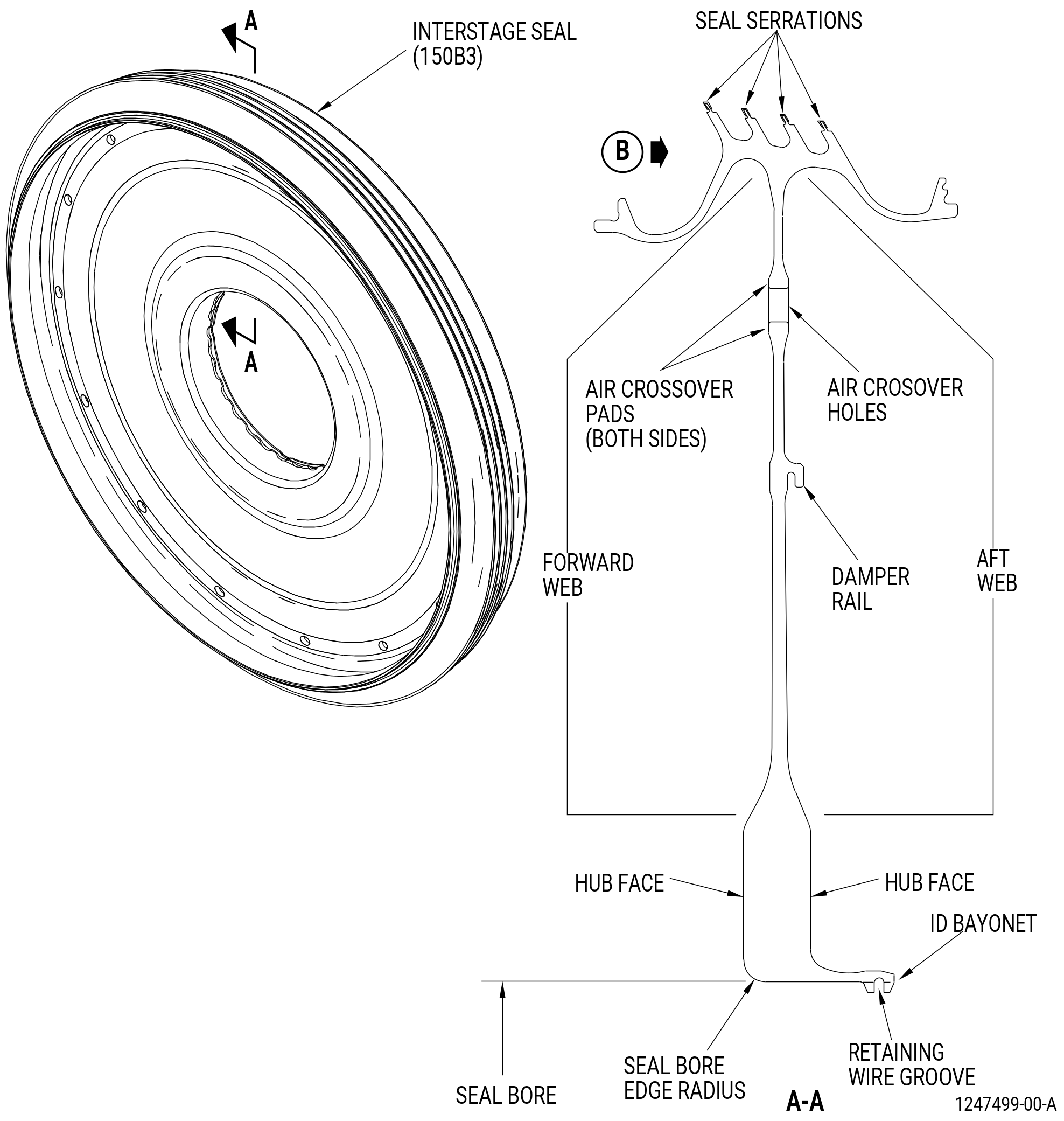
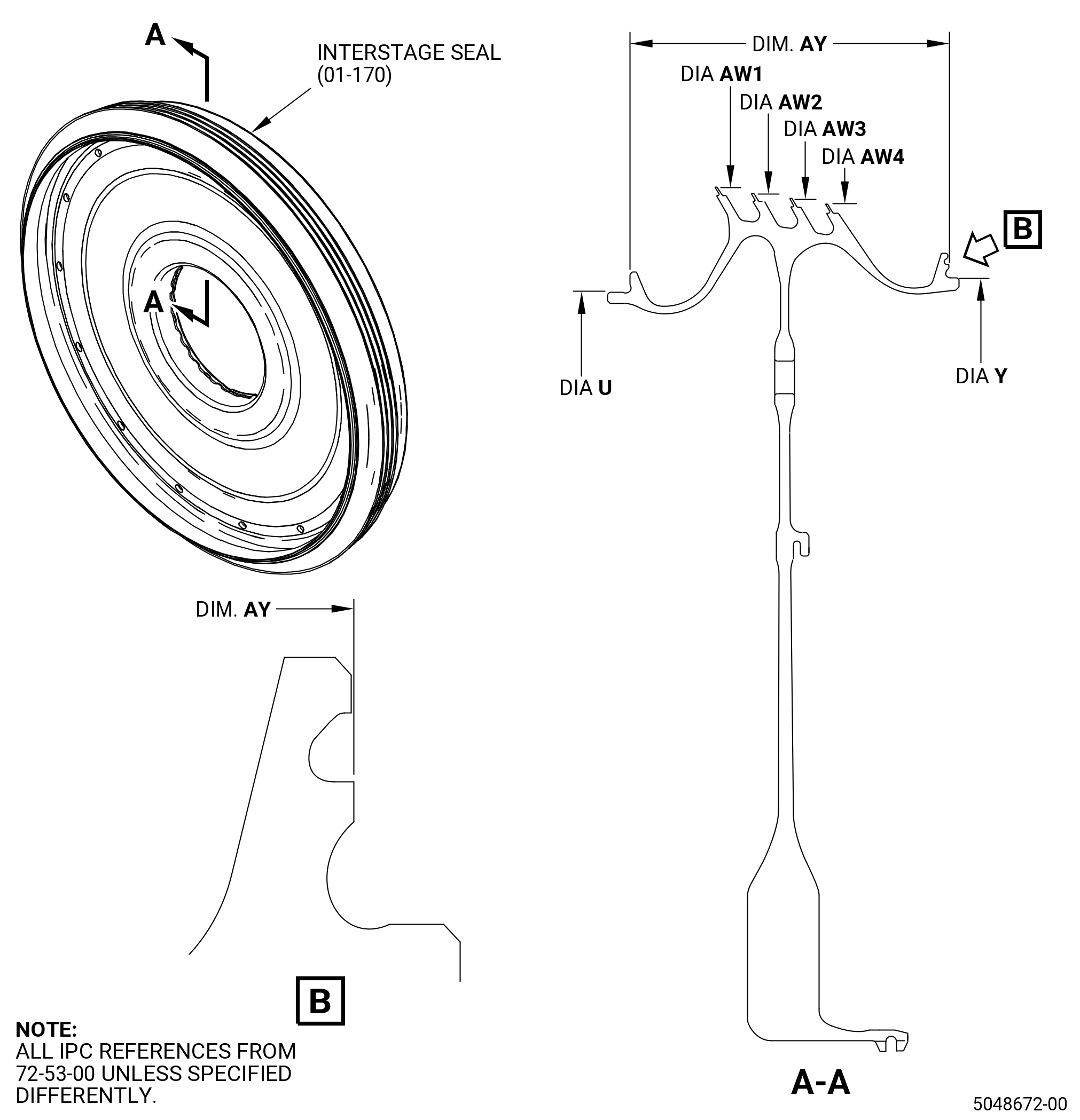
| A. | This procedure gives instructions to do an inspection of the high pressure turbine (HPT) rotor interstage seal (interstage seal) (01-170 , 72-53-00) (SIN 150B3) or (01-170A , 72-53-00) (SIN 150B3). |
| B. | There are two configurations for the interstage seal: |
| (1) | Configuration 1 interstage seal does not have a corrosion resistant coating on the outer rim surfaces of the seal. |
| (2) | Configuration 2 interstage seal has a corrosion resistant coating on the outer rim surfaces of the interstage seal. |
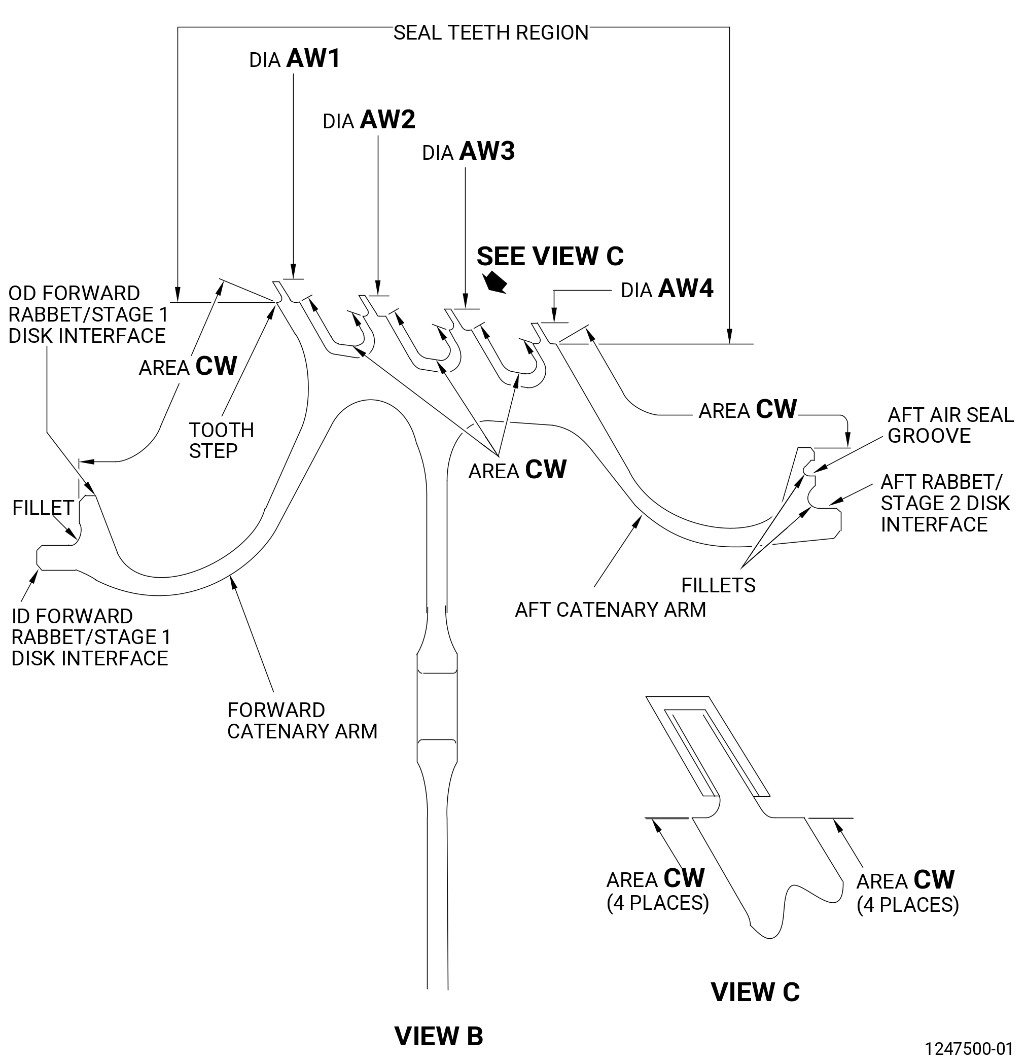
| (3) | For both configurations refer to area CW in Figure 801. |
| 2 . | Tools, Equipment, and Materials. |
| NOTE: |
|
| A. | Tools and Equipment. |
| (1) | Special Tools. None. |
| (2) | Standard Tools and Equipment. |
| (3) | Locally Manufactured Tools. None. |
| B. | Consumable Materials. |
|
| C. | Referenced Procedures. |
|
| D. | Expendable Parts. None. |
| 3 . | Specific Inspection Procedure. |
| NOTE: |
|
| Subtask 72-53-43-350-004 |
| A. | Remove the coating from the seal serrations of the interstage seal. Refer to TASK 72-53-43-300-801 (72-53-43, REPAIR 001). |
| Subtask 72-53-43-350-017 |
| B. | For configuration 2 parts only, remove the corrosion resistant coating from area CW of the interstage seal. Refer to TASK 72-53-43-300-802 (72-53-43, REPAIR 003). |
| Subtask 72-53-43-230-001 |
| C. | Do a Class G fluorescent penetrant inspection of the interstage seal. Refer to TASK 70-32-02-230-001 (FLUORESCENT PENETRANT INSPECTION) and as follows: |
| (1) | Apply non-aqueous wet developer (NAWD) to the air crossover hole to air crossover pad radii. |
| (2) | Indications more than 0.015 inch (0.38 mm) are not permitted. |
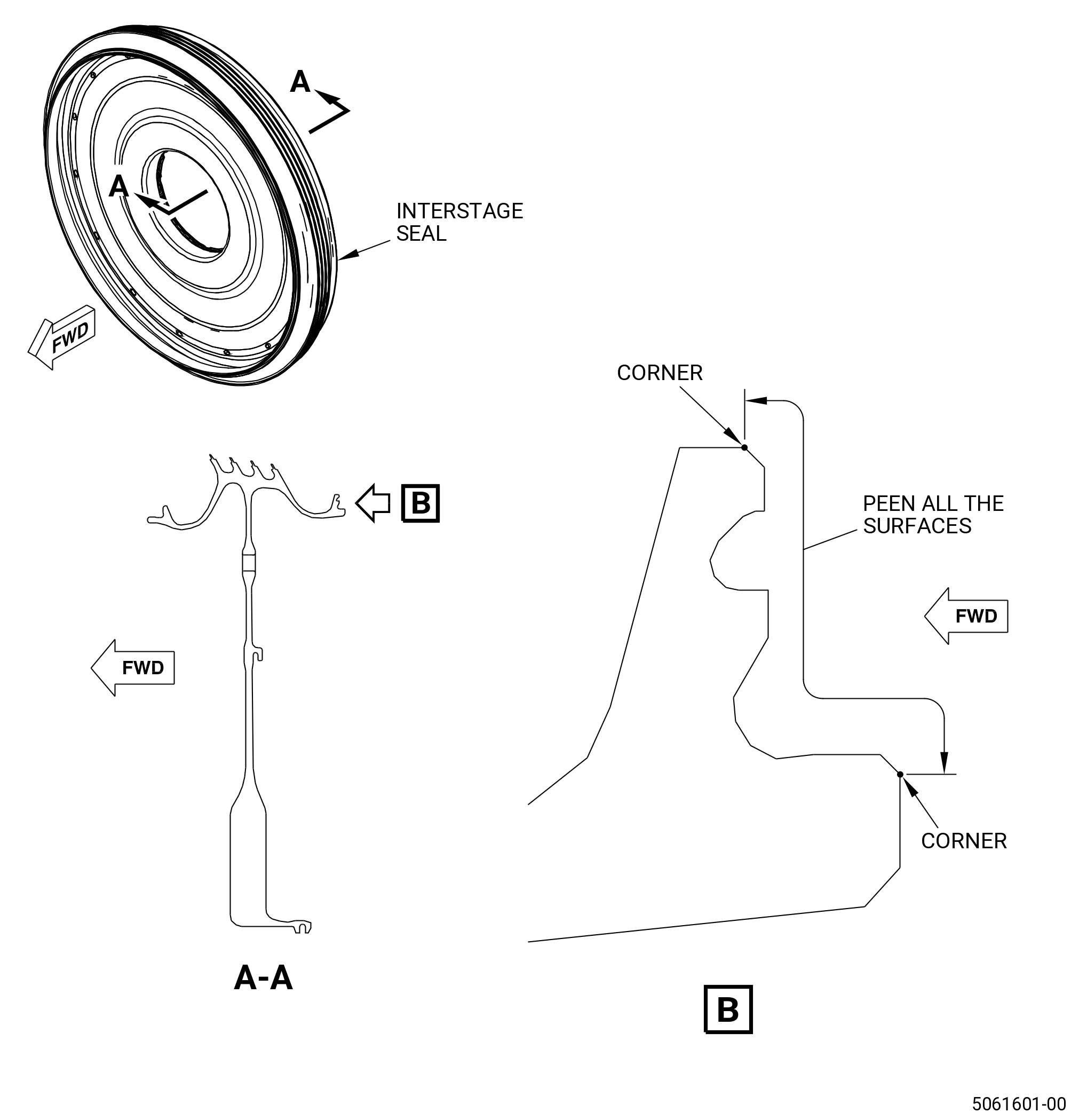
| (3) | Carefully examine the areas that follow because they are the most important. Refer to Figure 801. |
| • |
|
| • |
|
| • |
|
| • |
|
| • |
|
| • |
|
| Subtask 72-53-43-250-001 |
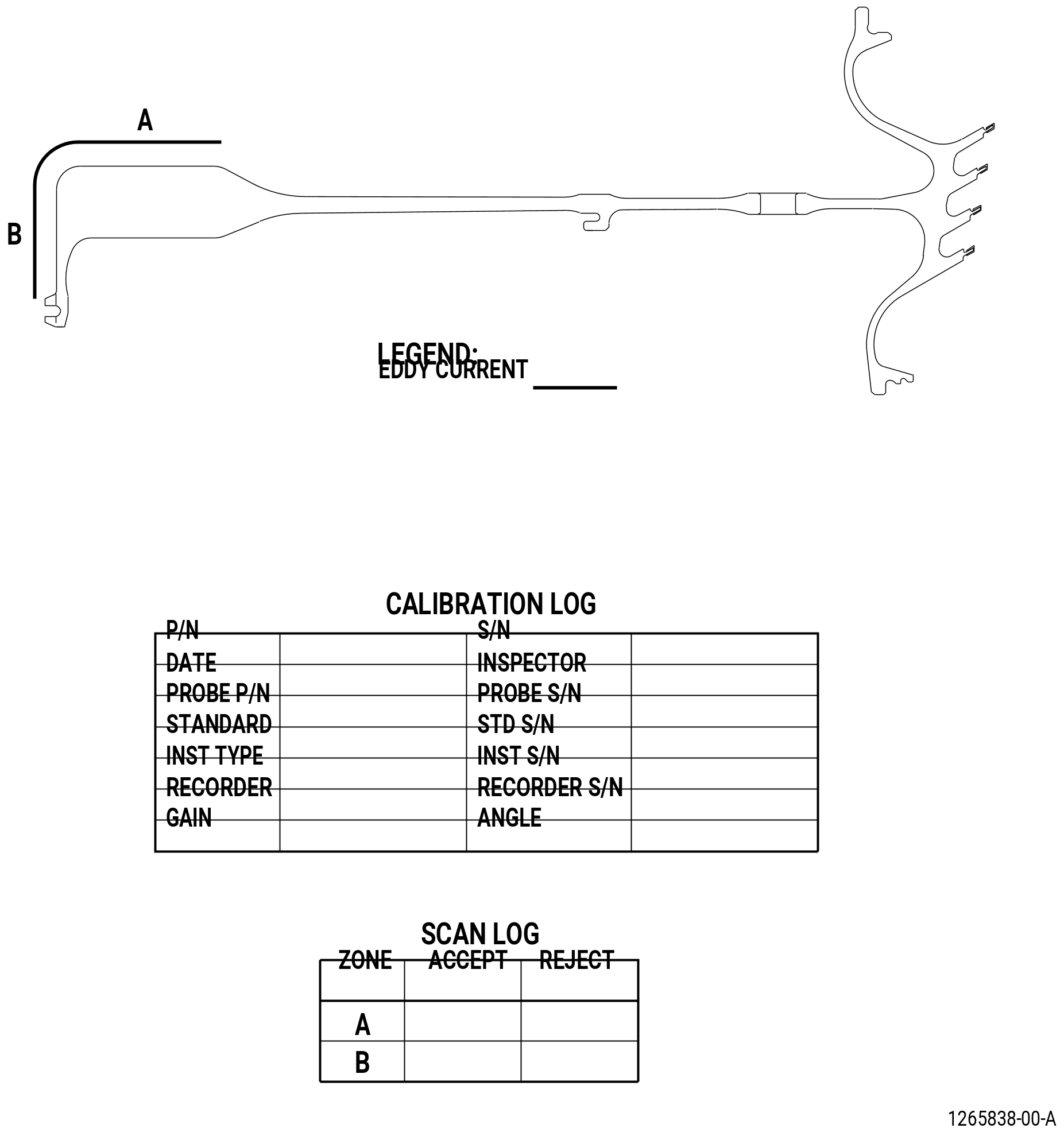
| D. | Do an eddy current inspection of the interstage seal bore as follows: |
| Subtask 72-53-43-160-001 |
| CAUTION: |
|
| (1) | Make sure that the interstage seal is clean. Refer to 72-53-43-100-801 (72-53-43, Cleaning 001). |
| Subtask 72-53-43-250-002 |
| (2) | Do an eddy current inspection of the bore surfaces. Refer to TASK 70-32-10-250-003 (2 MHZ EDDY CURRENT INSPECTION OF BORES IN ROTATING ENGINE HARDWARE USING SYSTEMS UNDER COMPUTER, NUMERIC, OR ROBOTIC CONTROL) and Figure 802. |
| NOTE: |
|
| (a) | If you change the equipment or the procedure specified in this inspection, it can have an unwanted effect on the inspection results. Before you change the equipment or the procedure, write to: |
| GE Aircraft Engines, OTC |
| One Neumann Way, MD: Q8 |
| Cincinnati, Ohio 45215 |
| USA |
| (b) | The material is Rene 88. Use correction factors for calibration as necessary. Refer to TASK 70-32-10-250-003 (2 MHZ EDDY CURRENT INSPECTION OF BORES IN ROTATING ENGINE HARDWARE USING SYSTEMS UNDER COMPUTER, NUMERIC, OR ROBOTIC CONTROL). |
| (c) | Use the GE-FQAP-428inspection kit to do an inspection of the bore zones shown in Figure 802. |
| (d) | Examine the inspection results. Use the limits that follow: |
| 1 | The eddy current inspection limit is 1500 mV. |
| 2 | If the amplitude of an indication is more than 1500 mV, the fan disk is not serviceable. |
| (e) | Complete the eddy current data sheets. |
| (f) | Make sure you complete all records during the eddy current inspection. Keep all records made during the inspection. |
| Subtask 72-53-43-220-116 |
| E. | Do a focused inspection of the air crossover holes of the interstage seal. Refer to TASK 72-53-43-800-801 (72-53-43, SPECIAL PROCEDURES 001). |
| 4 . | Visual Inspection. |
| Refer to Figure 801. |
| Subtask 72-53-43-220-001 |
| A. | Do an inspection of all areas of the interstage seal for: |
| (1) | Cracks: |
| Maximum serviceable limit: |
|
| Repair method: |
|
| Subtask 72-53-43-220-002 |
| B. | Do an inspection of all areas (this does not include the seal serrations, inner diameter (ID) bayonet pocket, forward and aft rabbet fillets, seal wire grove, air crossover holes, web and hub faces, stages 1 and 2 disk interfaces, seal bore, forward catenary arm, and aft catenary arm) of the interstage seal for: |
| (1) | Scratches: |
| Maximum serviceable limit: |
|
| Repair method: |
|
| Subtask 72-53-43-220-003 |
| (2) | Nicks and dents: |
| Maximum serviceable limit: |
|
| Repair method: |
|
| Subtask 72-53-43-220-004 |
| C. | Do an inspection of the seal serrations for: |
| (1) | Wear on the tip: |
| Maximum serviceable limit: |
|
| Repair method: |
|
| Subtask 72-53-43-220-006 |
| (2) | Nicks or dents: |
| Maximum serviceable limit: |
|
| Repair method: |
|
| Subtask 72-53-43-220-048 |
| (3) | Cracks or cracked out areas: |
| Maximum serviceable limit: |
|
| Repair method: |
|
| Subtask 72-53-43-220-007 |
| (4) | Bending: |
| Maximum serviceable limit: |
|
| Repair method: |
|
| Subtask 72-53-43-220-008 |
| (5) | Wear on diameters AW1, AW2, AW3, and AW4: |
| Maximum serviceable limit: |
|
| Repair method: |
|
| Subtask 72-53-43-220-009 |
| D. | Do an inspection of the ID bayonet pocket for: |
| (1) | Nicks, dents, scratches, or other damage: |
| Maximum serviceable limit: |
|
| Repair method: |
|
| Subtask 72-53-43-220-010 |
| E. | Do an inspection of the fillets for: |
| (1) | Nicks, dents, scratches, or other damage: |
| Maximum serviceable limit: |
|
| Repair method: |
|
| Subtask 72-53-43-220-011 |
| F. | Do an inspection of the air crossover holes (15 holes) for: |
| (1) | Nicks, dents, scratches, or other damage: |
| Maximum serviceable limit: |
|
| Repair method: |
|
| Subtask 72-53-43-220-013 |
| (2) | Damage at the edge radius: |
| Maximum serviceable limit: |
|
| Repair method: |
|
| Subtask 72-53-43-220-014 |
| G. | Do an inspection of the web and hub faces for: |
| NOTE: |
|
| (1) | Nicks, scratches, and fretting less than 0.250 inch (6.35 mm) from any fillet radius: |
| Maximum serviceable limit: |
|
| Repair method: |
|
| Subtask 72-53-43-220-015 |
| (2) | Nicks and scratches in other areas: |
| Maximum serviceable limit: |
|
| Repair method: |
|
| Subtask 72-53-43-220-016 |
| (3) | Dents: |
| Maximum serviceable limit: |
|
| Repair method: |
|
| Subtask 72-53-43-220-017 |
| H. | Do an inspection of the stage 1 disk interface and stage 2 disk interface for: |
| (1) | Fretting: |
| Maximum serviceable limit: |
|
| Repair method: |
|
| Subtask 72-53-43-220-018 |
| (2) | Nicks, dents, and scratches: |
| Maximum serviceable limit: |
|
| Repair method: |
|
| Subtask 72-53-43-220-020 |
| I. | Do an inspection of the seal bore for: |
| (1) | Nicks and scratches: |
| Maximum serviceable limit: |
|
| Repair method: |
|
| Subtask 72-53-43-220-021 |
| (2) | Dents: |
| Maximum serviceable limit: |
|
| Repair method: |
|
| Subtask 72-53-43-220-022 |
| (3) | Damage in the edge radius: |
| Maximum serviceable limit: |
|
| Repair method: |
|
| Subtask 72-53-43-220-023 |
| J. | Do an inspection of the forward catenary arm and aft catenary arm for: |
| (1) | Nicks, dents, scratches, or other damage: |
| Maximum serviceable limit: |
|
| Repair method: |
|
| Subtask 72-53-43-220-112 |
| (2) | Localized pitting or isolated deposited material on the inner diameter. Refer to Figure 803. |
| Maximum serviceable limit: |
|
| Maximum repairable limit: |
|
| Repair method: |
|
| • |
|
| • |
|
| • |
|
| 5 . | Dimensional Inspection. |
| Refer to Figure 804. |
| Subtask 72-53-43-220-024 |
| A. | Do an inspection of the interstage seal for: |
| (1) | Diameter U: |
| Minimum serviceable limit: |
|
| Maximum serviceable limit: |
|
| Repair method: |
|
| Subtask 72-53-43-220-025 |
| (2) | Dimension AY: |
| Minimum serviceable limit: |
|
| Maximum serviceable limit: |
|
| Repair method: |
|
| Subtask 72-53-43-220-026 |
| (3) | Diameter Y: |
| Minimum serviceable limit: |
|
| Maximum serviceable limit: |
|
| Repair method: |
|
| Subtask 72-53-43-220-027 |
| B. | Do an inspection of the seal serrations (AW1, AW2, AW3, AW4) as follows: |
| NOTE: |
|
| (1) | Diameter AW1: |
| Minimum serviceable limit: |
|
| Maximum serviceable limit: |
|
| Repair method: |
|
| Subtask 72-53-43-220-028 |
| (2) | Diameter AW2: |
| Minimum serviceable limit: |
|
| Maximum serviceable limit: |
|
| Repair method: |
|
| Subtask 72-53-43-220-029 |
| (3) | Diameter AW3: |
| Minimum serviceable limit: |
|
| Maximum serviceable limit: |
|
| Repair method: |
|
| Subtask 72-53-43-220-030 |
| (4) | Diameter AW4: |
| Minimum serviceable limit: |
|
| Maximum serviceable limit: |
|
| Repair method: |
|
| 6 . | Post Inspection Procedure. |
| Subtask 72-53-43-380-004 |
| A. | Shot peen the surfaces in the marked zones. Refer to Figure 805, TASK 70-47-01-380-016 (SHOTPEENING), and as follows: |
| (1) | Mask all the area that will not peen as follows: |
| (a) | Use C10-021 masking tape or an applicable equivalent as necessary. |
| (2) | Use C04-166 conditioned cut wire. |
| (3) | Shot peen to an intensity of 6-12N. |
| (4) | Use C10-205 test strips. |
| (5) | A minimum coverage of 125 percent is necessary. |
| (6) | Remove all the masking tape. |
| Subtask 72-53-43-350-002 |
| B. | Apply the coating to the seal serrations. Refer to TASK 72-53-43-300-801 (72-53-43, REPAIR 001). |
| Subtask 72-53-43-350-018 |
| C. | For configuration 2 parts only, apply the corrosion resistant coating to area CW. Refer to Figure 801 and TASK 72-53-43-300-802 (72-53-43, REPAIR 003). |