| GENX-1B CLEANING,INSPECTION,AND REPAIR MANUAL | Dated: 03/19/2021 | |
| CIR 72-53-44 , REPAIR 001 | ||
| HIGH PRESSURE TURBINE ROTOR AFT SEAL - REPAIR - BLEND REPAIR | ||
| GENX-1B CLEANING,INSPECTION,AND REPAIR MANUAL | Dated: 03/19/2021 | |
| CIR 72-53-44 , REPAIR 001 | ||
| HIGH PRESSURE TURBINE ROTOR AFT SEAL - REPAIR - BLEND REPAIR | ||
| * * * FOR ALL |
| TASK 72-53-44-300-801 |
| 1 . | Repair for the High Pressure Turbine Rotor Aft Seal. |
| A. | This procedure gives instructions to blend repair the high pressure turbine rotor aft seal (aft seal). |
| B. | The following Maximum Repairable limits apply to this repair: |
| NOTE: |
|
| NOTE: |
|
| (4) | Visual Inspection. |
| (a) | Do an inspection of all areas of the aft seal for: |
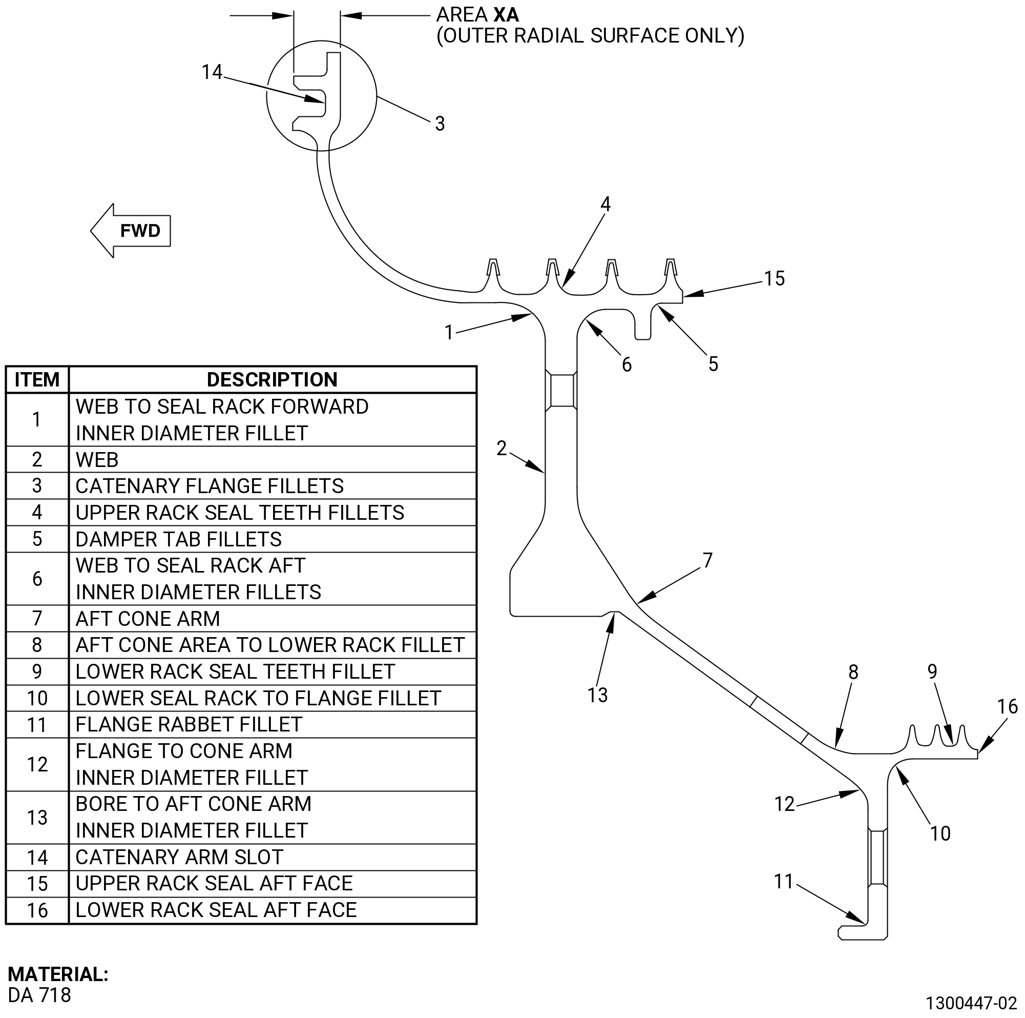
| 2 | Nicks, dents, and scratches (except in area XA, outer air hole, catenary arm inner diameter, hub faces, bore, seal serrations, outer rabbet, inner rabbet, inner flange rabbet, catenary arm slot radii, lower rack seal teeth fillets, flange rabbet fillet, upper rack seal teeth fillets, damper tab fillets, bore to aft cone arm inner diameter fillet, web to seal rack aft inner diameter fillet, lower seal rack to flange fillet, catenary flange fillets, flange to cone arm inner diameter fillet, and edge radii): |
| Maximum repairable limit: |
|
| Repair method: |
|
| a | Blend damage or defects in the web to seal rack forward inner diameter fillet and aft cone area to lower rack fillet at a minimum blend radius of 0.20 inch (5.1 mm). |
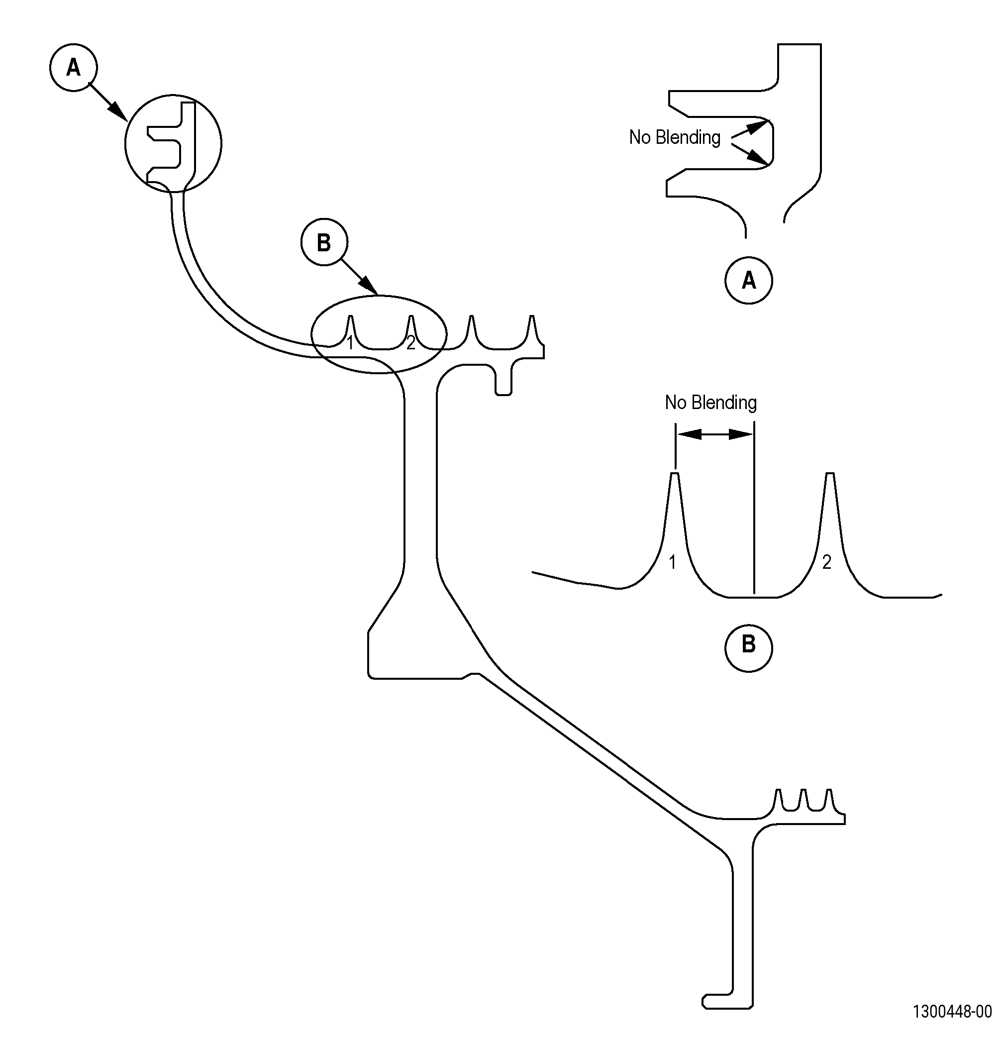
| b | Blend damage or defects in the web, aft cone arm, catenary arm slot vertical contact surface, upper rack seal aft face and lower rack seal aft face at a minimum blend radius of 0.50 inch (12.7 mm). Blending of the catenary arm slot vertical contact surface not allowed in areas displayed in Figure 902. |
| (c) | Do an inspection of the lower rack seal teeth fillets and flange rabbet fillet for: |
| 2 | Nicks, dents, and scratches: |
| Maximum repairable limit: |
|
| Repair method: |
|
| (d) | Do an inspection of the upper rack seal teeth fillets, damper tab fillets, and bore to aft cone arm inner diameter fillet for: |
| 2 | Nicks, dents, and scratches: |
| Maximum repairable limit: |
|
| Repair method: |
|
| (e) | Do an inspection of the web to seal rack aft inner diameter fillet, lower seal rack to flange fillet, catenary flange fillets, and flange to cone arm inner diameter fillet for: |
| 2 | Nicks, dents, and scratches: |
| Maximum repairable limit: |
|
| Repair method: |
|
| (f) | Do an inspection of the catenary arm inner diameter: |
| 2 | Nicks, dents, and scratches: |
| Maximum repairable limit: |
|
| Repair method: |
|
| (g) | Do an inspection of area XA (outer radial surface only) for: |
| 1 | Nicks and scratches: |
| Maximum repairable limit: |
|
| Repair method: |
|
| (h) | Do an inspection of outer seal serrations for: |
| 2 | Bending: |
| Maximum repairable limit: |
|
| Repair method: |
|
| 3 | Nicks, dents, and scratches: |
| Maximum repairable limit: |
|
| Repair method: |
|
| (i) | Do an inspection of sump seal teeth for: |
| 2 | Bending: |
| Maximum repairable limit: |
|
| Repair method: |
|
| 3 | Nicks, dents, and scratches: |
| Maximum repairable limit: |
|
| Repair method: |
|
| (j) | Do an inspection of the inner air holes (48 holes), and aft inner flange boltholes (15 boltholes) for: |
| 1 | Nicks, dents, and scratches: |
| Maximum repairable limit: |
|
| Repair method: |
|
| (k) | Do an inspection of the outer rabbet, inner rabbet, and inner flange rabbet for: |
| 1 | Fretting: |
| Maximum repairable limit: |
|
| Repair method: |
|
| 2 | Nicks, dents, and scratches: |
| Maximum repairable limit: |
|
| Repair method: |
|
| (l) | Do an inspection of the seal bore and hub face for: |
| 1 | Nicks, dents, and scratches: |
| Maximum repairable limit: |
|
| Repair method: |
|
| 2 | Damage in the edge radius: |
| Maximum repairable limit: |
|
| Repair method: |
|
| C. | The subsequent table gives a list of the part numbers that are applicable to this repair. All part numbers are applicable to all paragraphs unless specified differently. |
|
|||||||||||||||||||||||
| D. | Proprietary/Complex Process Statement. |
| (1) | None. |
| 2 . | Tools, Equipment, and Materials. |
| NOTE: |
|
| A. | Tools and Equipment. |
| (1) | Special Tools. None. |
| (2) | Standard Tools and Equipment. None. |
| (3) | Locally Manufactured Tools. None. |
| B. | Consumable Materials. |
|
| C. | Referenced Procedures. |
| D. | Expendable Parts. None. |
| E. | SPD Information. None. |
| F. | Special Solutions. None. |
| G. | Test Specimens. None. |
| 3 . | Dimensional Information. |
| None. |
| 4 . | Setup Information. |
| None. |
| 5 . | Procedure. |
| Subtask 72-53-44-350-001 |
| A. | Blend the repairable regions of the aft seal. Refer to TASK 70-42-00-350-002 (BLENDING AND REMOVAL OF HIGH METAL PROCEDURES), and TASK 72-53-44-300-801 (72-53-44, paragraph 1.B.). |
| Subtask 72-53-44-110-004 |
| B. | Etch the aft seal blended areas. Refer to TASK 70-24-00-110-033 (ETCHING PROCEDURES FOR FLUORESCENT-PENETRANT INSPECTION) , TASK 70-24-01-110-034 (SWAB ETCHING PROCEDURE) , and as follows: |
| (1) | Use class C or G etchant. |
| Subtask 72-53-44-230-003 |
| C. | Alternative Procedure Available. Do an inspection of the aft seal blended areas. Refer to TASK 70-32-00-200-002 (INDIRECT INSPECTION METHODS), TASK 70-32-02-230-001 (FLUORESCENT PENETRANT INSPECTION), and as follows: |
| (1) | Use class G penetrant. |
| (2) | Refer to TASK 72-53-44-200-801 (72-53-44, INSPECTION 001) for inspection limits. |
| Subtask 72-53-44-230-004 |
| C.A. | Alternative Procedure. Do an inspection of the aft seal blended areas. Refer to TASK 70-32-00-200-002 (INDIRECT INSPECTION METHODS) TASK 70-32-03-230-002 (SPOT-FLUORESCENT-PENETRANT INSPECTION), and as follows: |
| (1) | Use class G penetrant. |
| (2) | Refer to TASK 72-53-44-200-801 (72-53-44, INSPECTION 001) for rejection criteria. |
| Subtask 72-53-44-350-002 |
| D. | Polish to remove the effects of the swab etch with a C10-010 Scotch Brite pad. |
| Subtask 72-53-44-350-003 |
| E. | Apply C10-021 plastic tape to coated seal teeth. |
| Subtask 72-53-44-380-001 |
| F. | Peen the aft seal blended areas, except the catenary arm slot. Refer to TASK 70-47-01-380-016 (SHOTPEENING) and as follows: |
| (1) | Use C04-286 S110 shot. |
| (2) | Intensity to 0.006-0.012 N. |
| Subtask 72-53-44-350-004 |
| G. | Remove the plastic tape from seal teeth. |
| Subtask 72-53-44-100-001 |
| H. | Clean the aft seal. Refer to TASK 72-53-44-100-801 (72-53-44, CLEANING 001). |
| Subtask 72-53-44-200-002 |
| I. | Inspect the aft seal. Refer to TASK 72-53-44-200-801 (72-53-44, INSPECTION 001). |