| GENX-1B CLEANING,INSPECTION,AND REPAIR MANUAL | Dated: 03/26/2021 | |
| CIR 72-64-12 , REPAIR 001 | ||
| AXIAL LINK - REPAIR - SPHERICAL BEARING REPLACEMENT | ||
| GENX-1B CLEANING,INSPECTION,AND REPAIR MANUAL | Dated: 03/26/2021 | |
| CIR 72-64-12 , REPAIR 001 | ||
| AXIAL LINK - REPAIR - SPHERICAL BEARING REPLACEMENT | ||
| * * * FOR ALL |
| TASK 72-64-12-300-801 |
| 1 . | Repair for the Axial Link. |
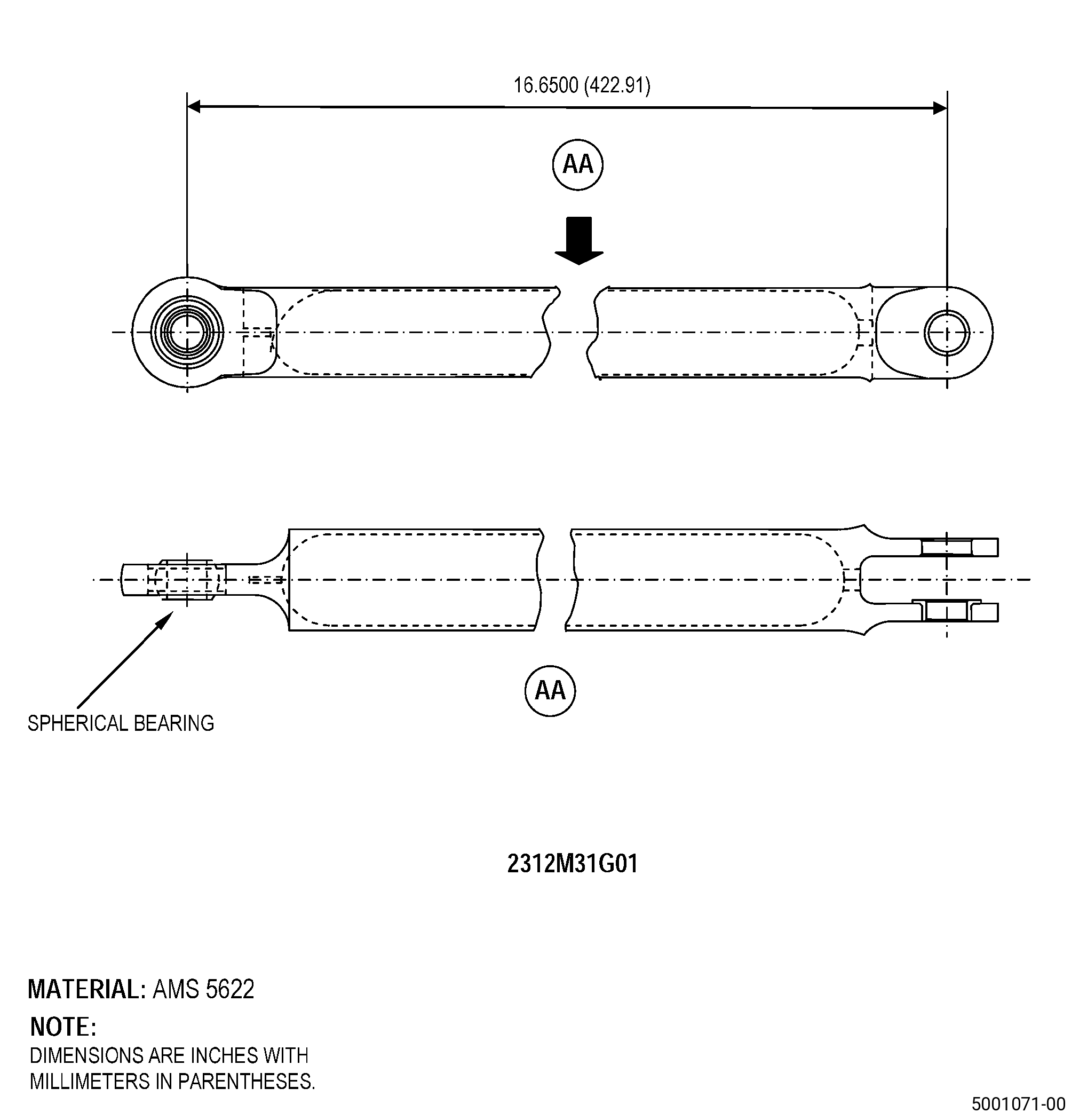
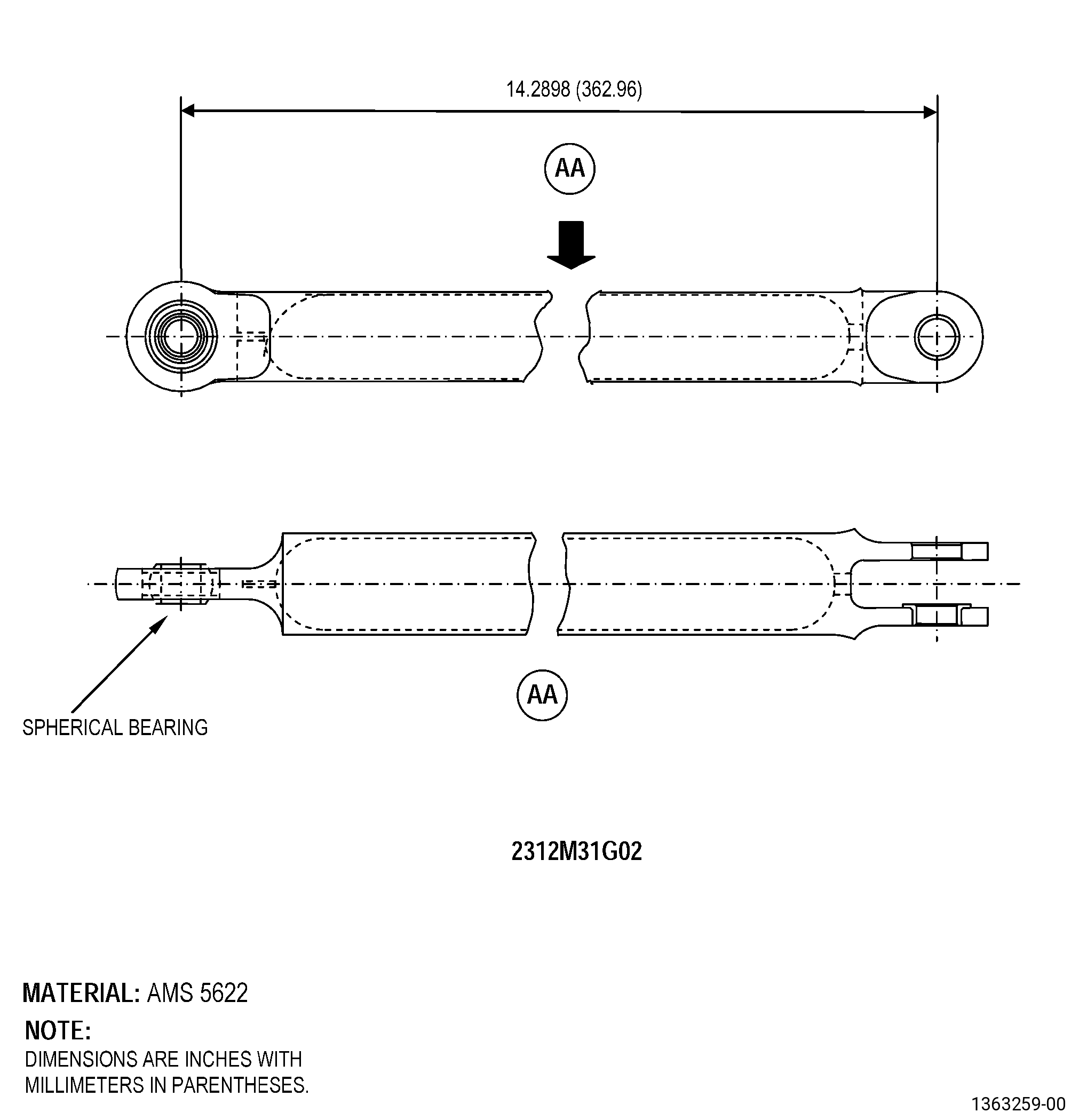
| A. | This procedure gives instructions to repair the axial link by replacing the damaged spherical bearing. Refer to Figure 901. |
| B. | The following maximum repairable limits apply to this repair: |
| NOTE: |
|
| NOTE: |
|
| (4) | Visual Inspection. |
| (b) | Do an inspection of the spherical bearing for: |
| 1 | Nicks, dents, or scratches: |
| Maximum repairable limit: |
|
| 3 | Wear on the sphere ID and on the spherical surfaces: |
| Maximum repairable limit: |
|
| (5) | Dimensional Inspection. |
| (a) | Do an inspection of the subsequent diameters: |
| 1 | Diameter C (bearing internal diameter): |
| Maximum repairable limit: |
|
| C. | The subsequent table gives a list of the part numbers that are applicable to this repair. All part numbers are applicable to all paragraphs unless specified differently. |
|
|||||||||||||||||||||||
| D. | Proprietary/Complex Process Statement. |
| (1) | None. |
| 2 . | Tools, Equipment, and Materials. |
| NOTE: |
|
| A. | Tools and Equipment. |
| (1) | Special Tools. None. |
| (2) | Standard Tools and Equipment. |
| (3) | Locally Manufactured Tools. None. |
| B. | Consumable Materials. |
|
| C. | Referenced Procedures. |
|
| D. | Expendable Parts. None. |
| E. | SPD Information. |
|
| F. | Special Solutions. None. |
| G. | Test Specimens. None. |
| 3 . | Dimensional Information. |
| Subtask 72-64-12-220-013 |
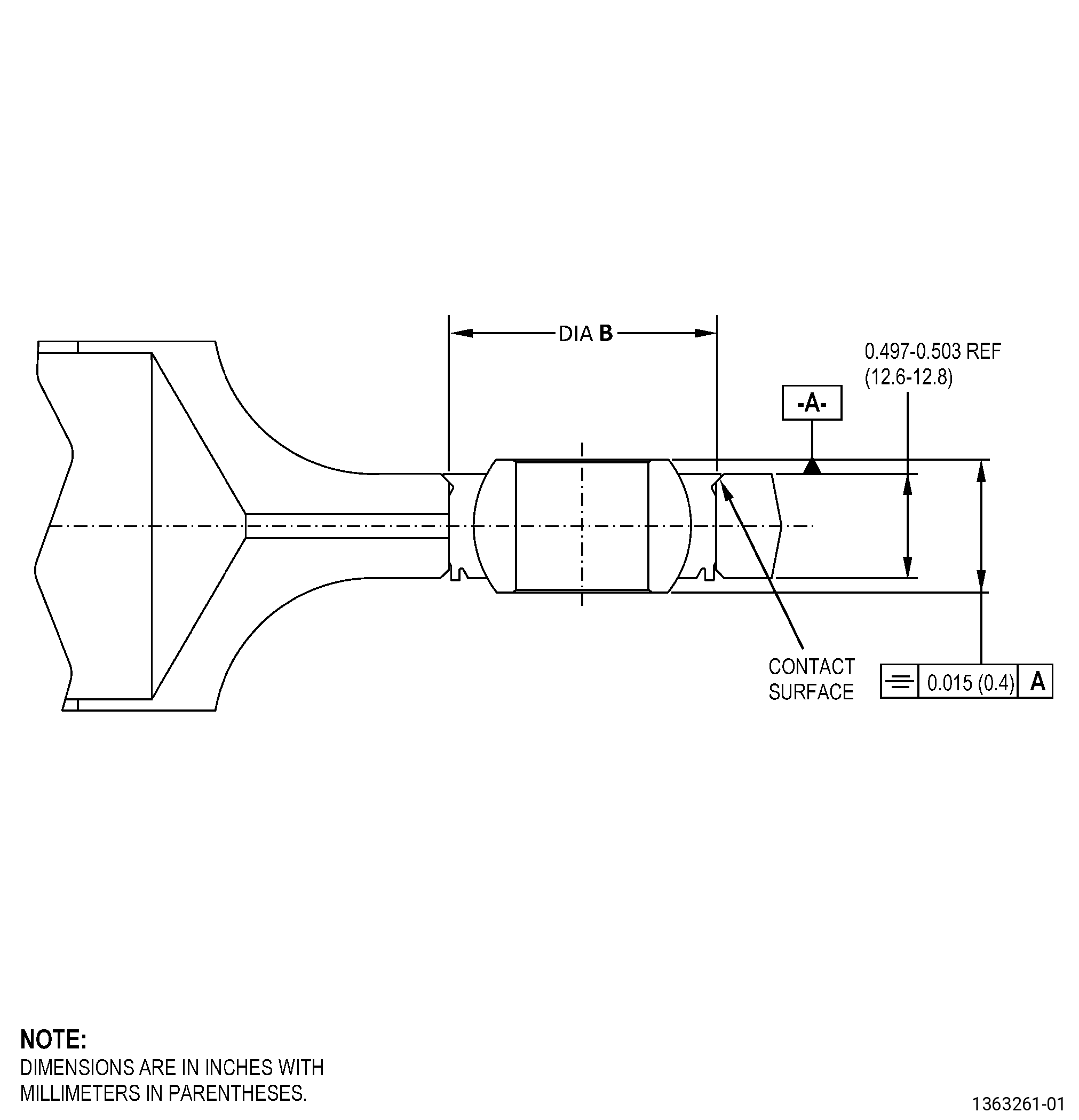
| A. | Refer to Figure 901 for specified dimensionsand locations. |
| NOTE: |
|
| NOTE: |
|
|
| 4 . | Setup Information. |
| Subtask 72-64-12-350-001 |
| A. | Set-up the axial linkto machine the swaged lip of the spherical bearing as follows: |
| NOTE: |
|
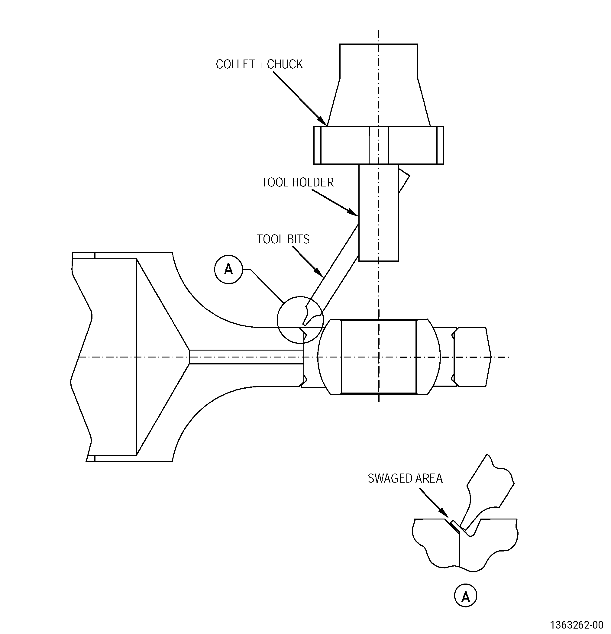
| (1) | Put the base assembly and the axiallink on the machine table. Refer to Figure 901, Figure 902, Figure 903, and as follows: |
| (a) | Make sure that the axial link surfaceadjacent to the spherical bearing is perpendicular to the machinespindle to 0.0011 inch (0.03 mm) or less. |
| (b) | Align the machine spindle with theinner diameter (ID) of the spherical bearing to 0.0011 inch (0.03mm) or less. |
| (2) | Use clamps to attach the axial linkto the machine table. |
| Subtask 72-64-12-350-005 |
| B. | Set-up the axial linkto remove the spherical bearing as follows: |
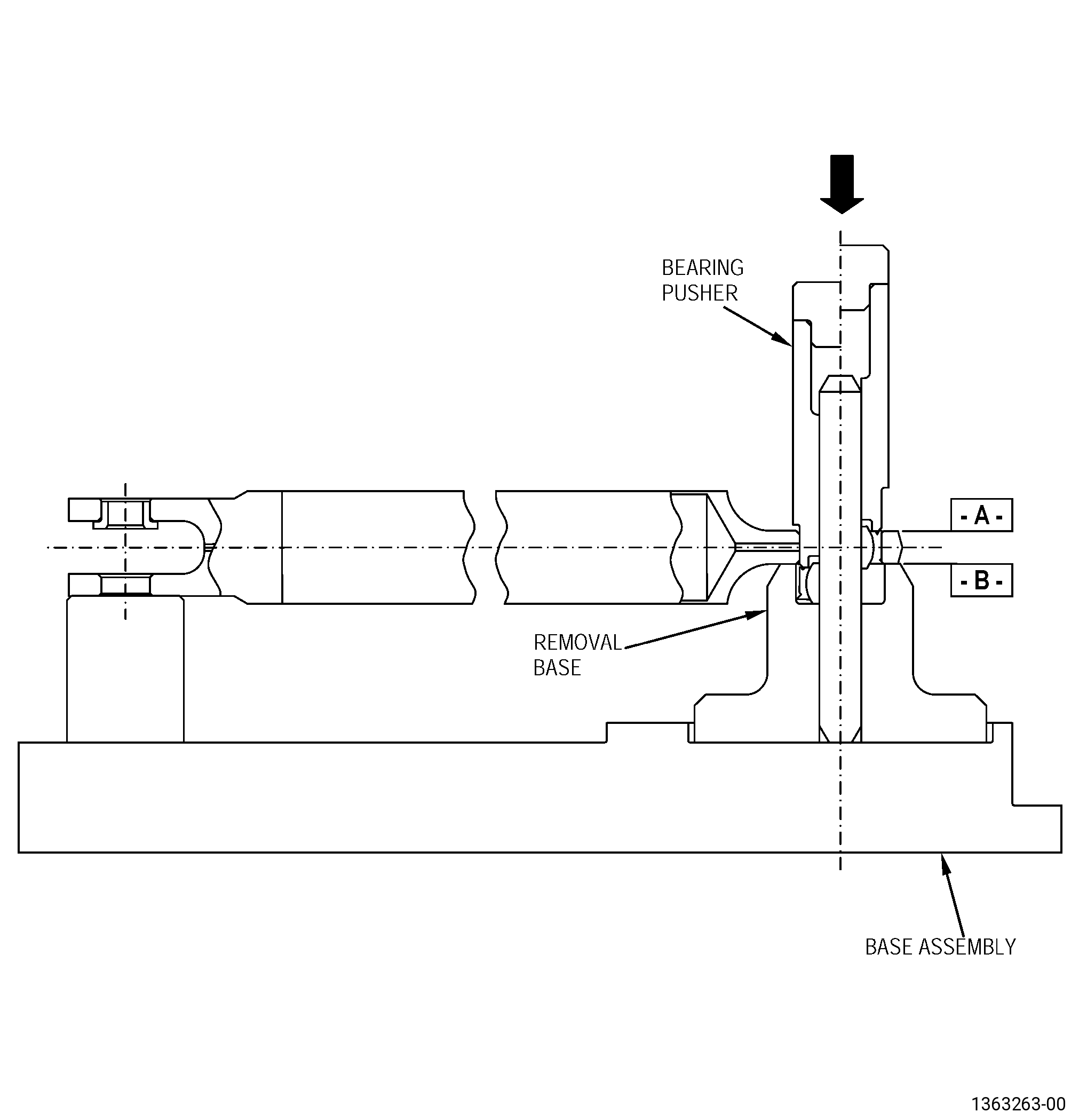
| (1) | Put the base assembly on the arborpress table and then put the axial link on the removal base. Referto Figure 904. |
| NOTE: |
|
| (2) | Make sure that the axial link surfacewith the machined swaged lip is up. |
| Subtask 72-64-12-350-006 |
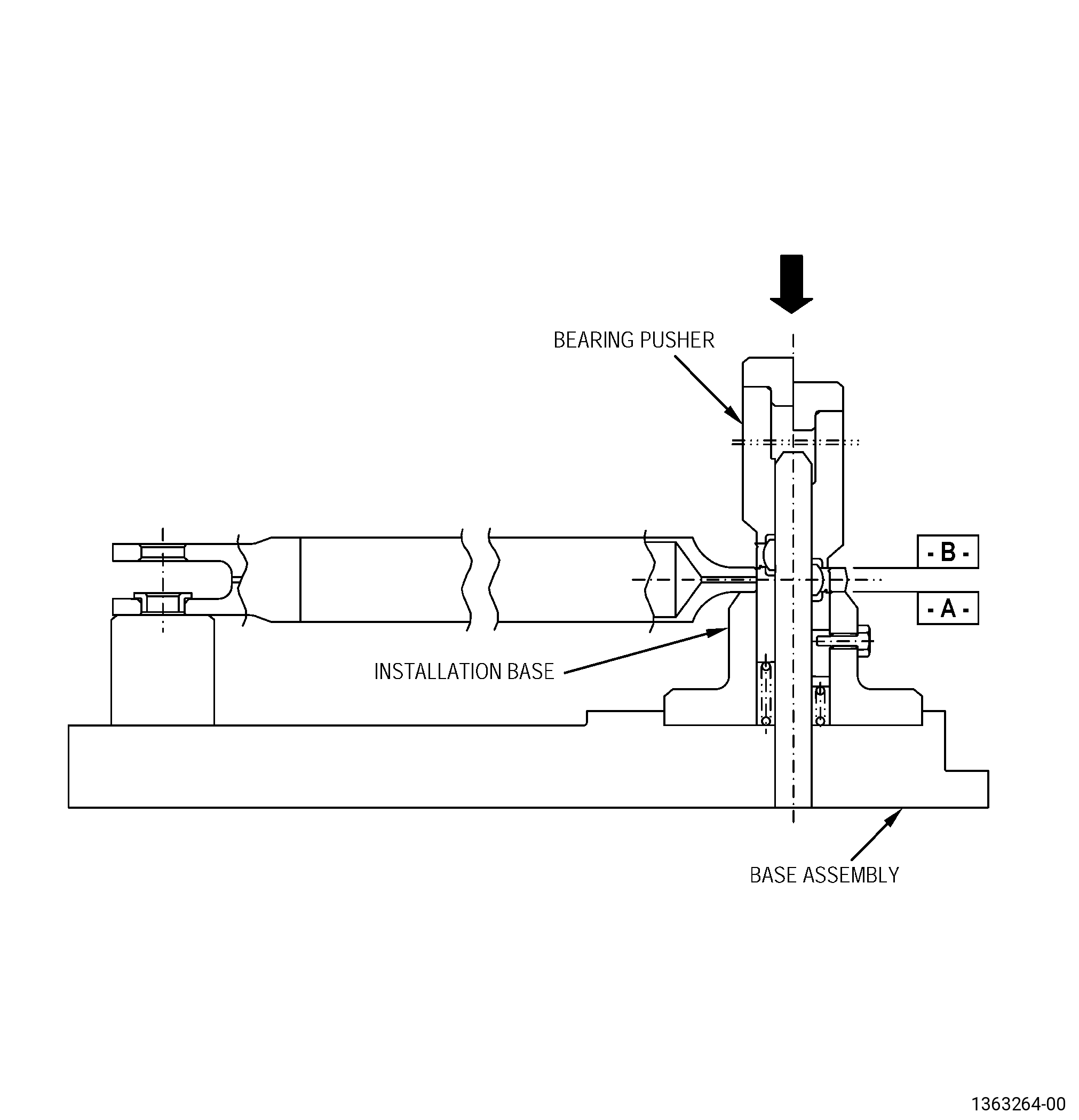
| C. | Set-up the axial linkto install the spherical bearing as follows: |
| (1) | Put the base assembly on the arborpress table and then put the axial link on the installation base topilot the spherical bearing ID on the spherical bearing support. Referto Figure 905. |
| NOTE: |
|
| (2) | Push the spherical bearing into theaxial link until it bottoms out in the fixture. The spherical bearingmust be flush with the axial link. |
| Subtask 72-64-12-350-007 |
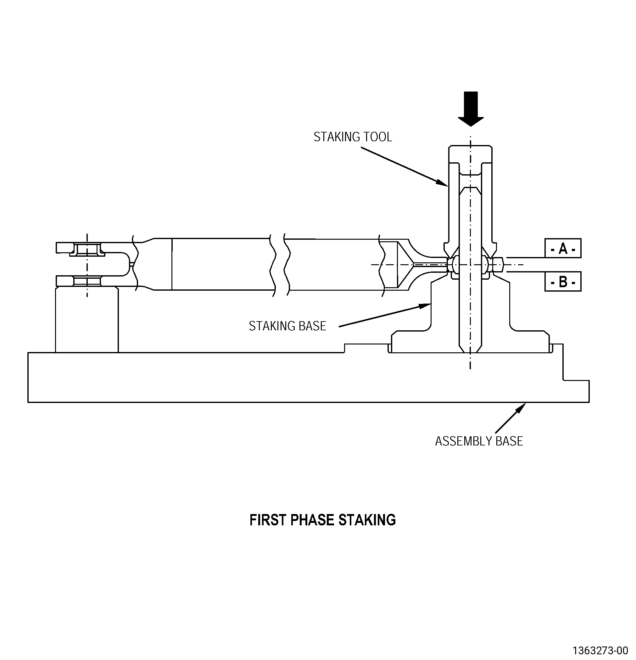
| D. | Set-up the axial linkto stake the swage lip of the spherical bearing as follows: |
| (1) | Put the base assembly on the arborpress table. |
| (2) | Put the axial link on the staking baseto pilot the spherical bearing ID on the staking tool. Refer to Figure 906. |
| NOTE: |
|
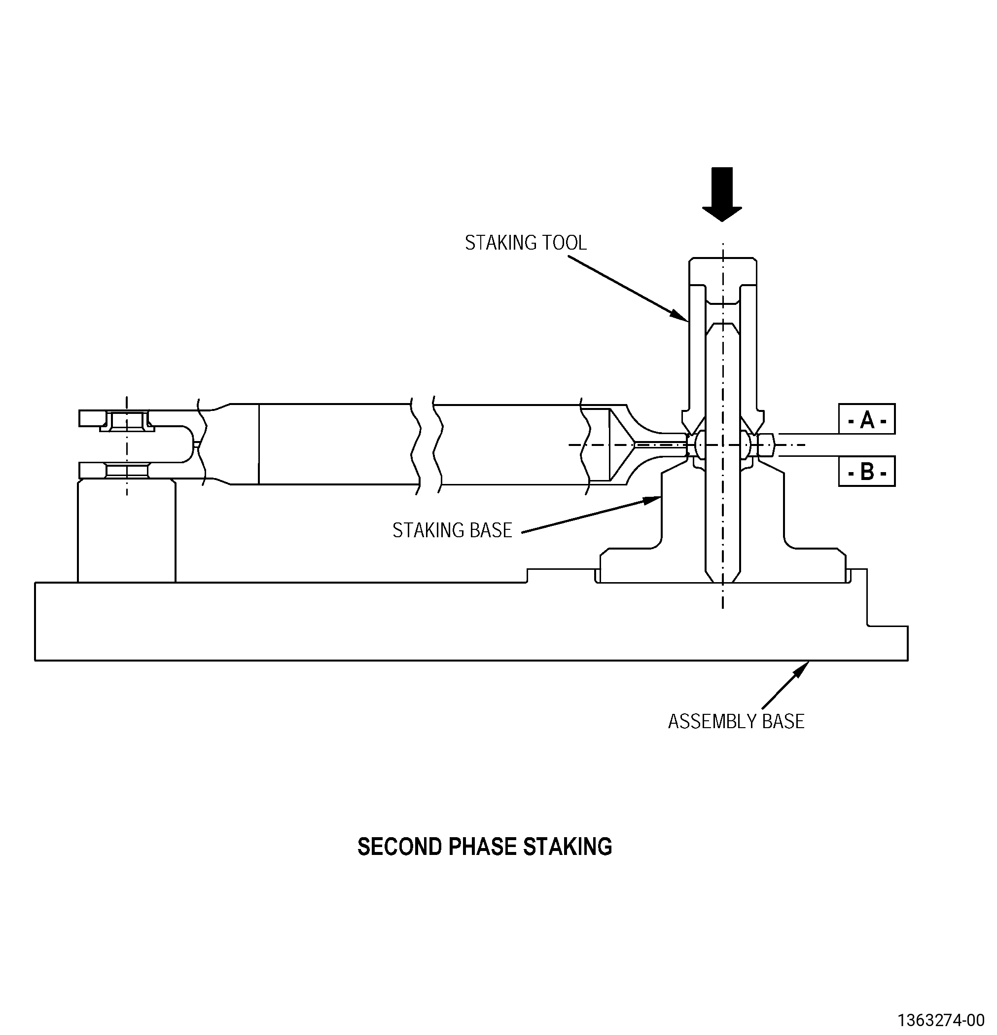
| (3) | Move the axial link in the oppositedirection to stake the other side of the spherical bearing. Referto Figure 907. |
| 5 . | Procedure. |
| Subtask 72-64-12-350-002 |
| A. | Remove the sphericalbearing from the axial link as follows: |
| Subtask 72-64-12-320-001 |
| CAUTION: |
|
| (1) | Machine the axial link. Refer to TASK 70-00-03-800-004(MACHINING DATA), Figure 903, and as follows: |
| (a) | Set-up the axial link to machine theswaged lip of the spherical bearing. Refer to Subtask 72-64-12-350-001 (paragraph 4.A.),Setup Information. |
| (b) | Machine the axial link to weaken theswaged lip of the spherical bearing. |
| Subtask 72-64-12-350-008 |
| CAUTION: |
|
| (2) | Remove the spherical bearing as follows: |
| (a) | Set-up the axial link to remove thespherical bearing. Refer to Subtask 72-64-12-350-005 (paragraph 4.B.),Setup Information. |
| (b) | Put the spherical bearing pusher toolon the axial link and align it on the top of the spherical bearing.Refer to Figure 904. |
| (c) | Push on the side where you removedthe staking swaged lip of the spherical bearing. |
| (d) | Apply pressure to the top of the pusherwith the ram of the arbor press to remove the spherical bearing. |
| Subtask 72-64-12-220-016 |
| B. | Do a dimensional inspectionof the center bore of the axial link. Refer to Subtask 72-64-12-220-013 (paragraph 3.A.), Figure 902, and do as follows: |
| Subtask 72-64-12-350-009 |
| (1) | If necessary, blend the axial linkto remove all the high metal. Refer to TASK 70-42-00-350-002(BLENDING AND REMOVAL OF HIGH METAL PROCEDURES). |
| Subtask 72-64-12-110-002 |
| C. | Etch the axial linkrepair area. Refer to TASK 70-24-00-110-033 (ETCHING PROCEDURESFOR FLUORESCENT-PENETRANT INSPECTION), TASK 70-24-01-110-034(SWAB ETCHING PROCEDURE), and as follows: |
| (1) | Use Class C etchant. |
| Subtask 72-64-12-200-001 |
| D. | Do an inspection ofthe axial link repair area. Refer to TASK 70-32-00-200-002(INDIRECT INSPECTION METHODS), TASK 70-32-02-230-001(FLUORESCENT PENETRANT INSPECTION), and as follows: |
| (1) | Use Class A penetrant. |
| (2) | Linear indications are not permitted. |
| NOTE: |
|
| (3) | Indications 0.0299 inch (0.76 mm) orless are permitted. |
| (4) | Indications 0.0304-0.0598 inch (0.77-1.52mm) are permitted if there is a minimum space of 0.500 inch (12.7mm) between them. |
| Subtask 72-64-12-100-001 |
| E. | Clean the axial link.Refer to TASK 70-21-00-110-051 (CHEMICAL CLEANING) and TASK 70-21-03-160-001(CLEANING METHOD NO. 3 - STEAM CLEANING). |
| Subtask 72-64-12-110-003 |
| F. | Clean the new sphericalbearing, ABK10VCR-3. Refer to TASK 70-21-00-110-051 (CHEMICAL CLEANING) and TASK 70-21-23-110-053(CLEANING METHOD 23 - HAND-WIPE DEGREASING). |
| Subtask 72-64-12-300-001 |
| G. | Install the new sphericalbearing, ABK10VCR-3, in the axial link as follows: |
| (1) | Set-up the axial link to install thespherical bearing. Refer to Subtask 72-64-12-350-006 (paragraph 4.C.),Setup Information and as follows: |
| WARNING: |
|
| (2) | Increase the temperature of the axial link area where you willinstall the spherical bearing with a C10-054 hot air gun to a temperature range of 203to 212°F (95 to 100°C). Use a pyrometer to do a check of thetemperature. |
| WARNING: |
|
| (3) | Freeze the spherical bearing in dry ice or liquid nitrogen.Refer to TASK 70-14-00-620-003 (HANDLING OF BEARINGS). |
| Subtask 72-64-12-350-003 |
| CAUTION: |
|
| CAUTION: |
|
| (4) | Install the spherical bearing into the axial link bore. Referto Figure 905 andas follows: |
| (a) | Install the spherical bearing as soonas possible after the heating and freezing operations. |
| (b) | Use the bearing pusher. |
| (c) | Point the entry slot as shown in Figure 905. |
| (d) | Apply a maximum load of 1124 lb (5000N) to the outer ring of the spherical bearing. |
| Subtask 72-64-12-350-004 |
| H. | Stake the new sphericalbearing, ABK10VCR-3, to the axial link. Refer to Figure 906 and as follows: |
| (1) | Set-up the axial link to stake theswage lip of the spherical bearing. Refer to Subtask 72-64-12-350-007 (paragraph 4.D.),Setup Information and as follows: |
| (a) | Make sure that the spherical bearinginstalled in the axial link bore agrees with the symmetry tolerancewhen you stake the spherical bearing on the axial link chamfer bore.Refer to Figure 902. |
| Subtask 72-64-12-350-010 |
| (2) | For the first phase staking, referto Figure 906, andas follows: |
| (a) | Use the applicable staking tool tostake the spherical bearing. Refer to paragraph 2.A.(2), StandardTools and Equipment and as follows: |
| 1 | Use the circular staking tool (withthe internal angle not higher than 30 degrees and the external anglenot higher than 45 degrees) to stake the groove of the spherical bearing. |
| (b) | Gradually apply a load to a maximumof 21018 lb (93500 N) on the end of the spherical bearing housing. |
| (c) | Make a retention lip in the sphericalbearing race until it touches the axial link bore chamfer. |
| (d) | Repeat lip swaging operation each 90°. |
| Subtask 72-64-12-350-011 |
| (3) | For the second phase staking, referto Figure 907, andas follows: |
| (a) | Use the applicable staking tool tostake the spherical bearing. Refer to paragraph 2.A.(2), StandardTools and Equipment and as follows: |
| 1 | Use the circular staking tool (withthe internal angle not higher than 30 degrees and the external anglenot higher than 45 degrees) to stake the groove of the spherical bearing. |
| (b) | Gradually apply a load to a maximumof 21018 lb (93500 N) on the end of the spherical bearing housing. |
| (c) | Make a retention lip in the sphericalbearing race until it touches the axial link bore chamfer. |
| (d) | Repeat lip swaging operation each 90°. |
| Subtask 72-64-12-220-014 |
| I. | Do a visual inspectionin the swaged area of the spherical bearing as follows: |
| (1) | Linear indications are not permitted. |
| NOTE: |
|
| Subtask 72-64-12-220-015 |
| J. | Do an inspection ofthe new spherical bearing installation, ABK10VCR-3, in the axial linkas follows: |
| (1) | Do an inspection of the ball for freemovement as follows: |
| (a) | Use finger pressure to move the ball. |
| Subtask 72-64-12-210-001 |
| (2) | Do a check of the radial play as follows: |
| (a) | Make sure that the radial play thatis below a load of 5.5 lb (24.5 N) between the spherical bearing balland the ball spherical bearing seat is 0.00099-0.0019 inch (0.025-0.050mm). |
| Subtask 72-64-12-300-002 |
| (3) | If the movement is not free and theradial clearance does not agree with the limits specified in Subtask 72-64-12-210-001(paragraph 5.J.(2)(a)), remove the spherical bearing andinstall a new spherical bearing as follows: |
| (a) | Do Subtask 72-64-12-350-002 (paragraph 5.A.) thru Subtask 72-64-12-220-015(paragraph 5.J.) again. |
| (b) | Use less staking force in the installation. |
| Subtask 72-64-12-220-017 |
| NOTE: |
|
| (4) | Do an inspection for symmetry. Referto Figure 902. |