| GENX-1B CLEANING,INSPECTION,AND REPAIR MANUAL | Dated: 12/27/2022 | |
| CIR 72-31-44, REPAIR 001 | ||
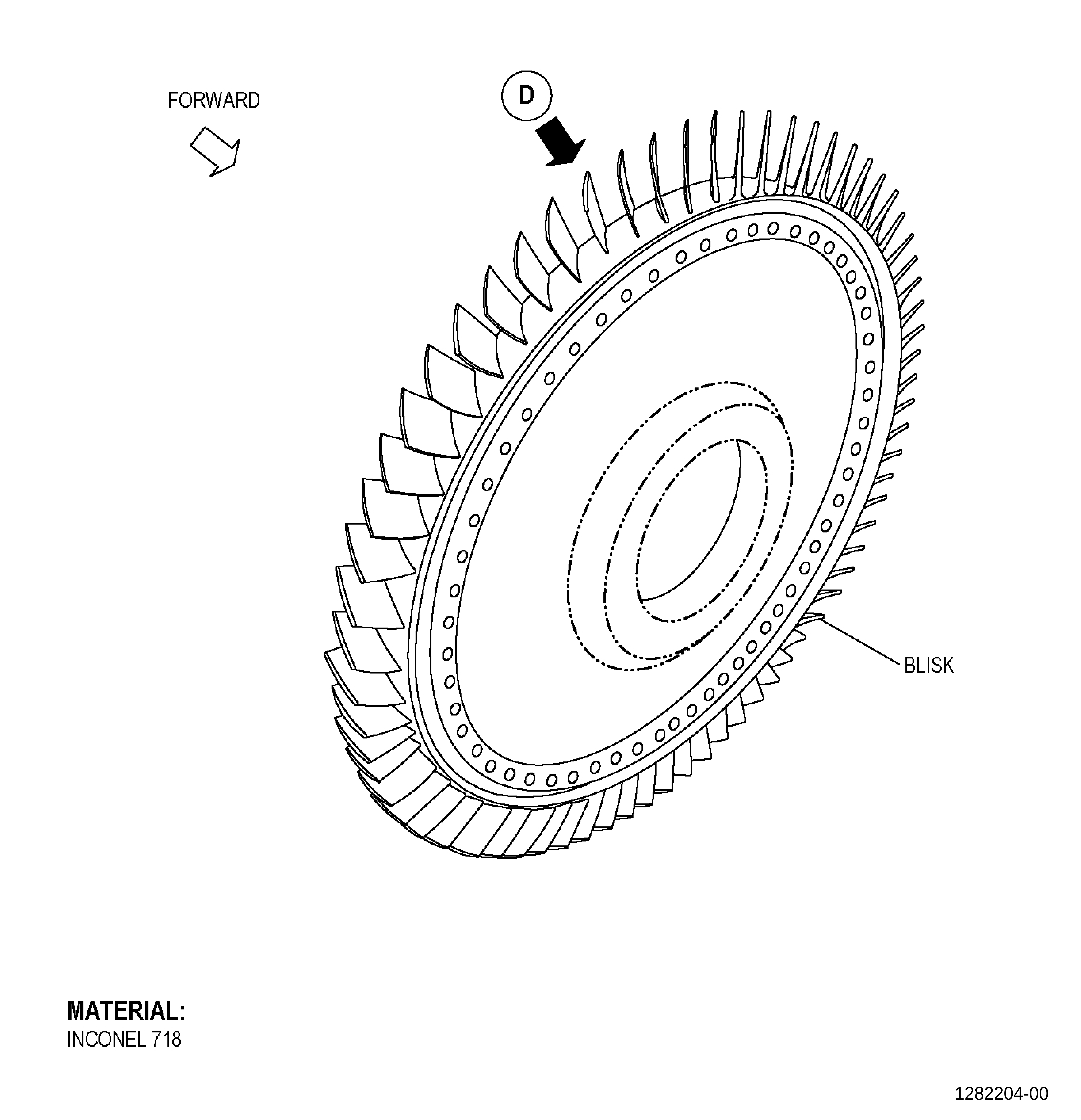
| HIGH PRESSURE COMPRESSOR ROTOR STAGE 5 BLISK - REPAIR - PLATFORM BLENDING REPAIR | ||
| GENX-1B CLEANING,INSPECTION,AND REPAIR MANUAL | Dated: 12/27/2022 | |
| CIR 72-31-44, REPAIR 001 | ||
| HIGH PRESSURE COMPRESSOR ROTOR STAGE 5 BLISK - REPAIR - PLATFORM BLENDING REPAIR | ||
| * * * FOR ALL |
| TASK 72-31-44-300-802 |
| 1. | Repair for the High Pressure Compressor Rotor Stage 5 Blisk. |
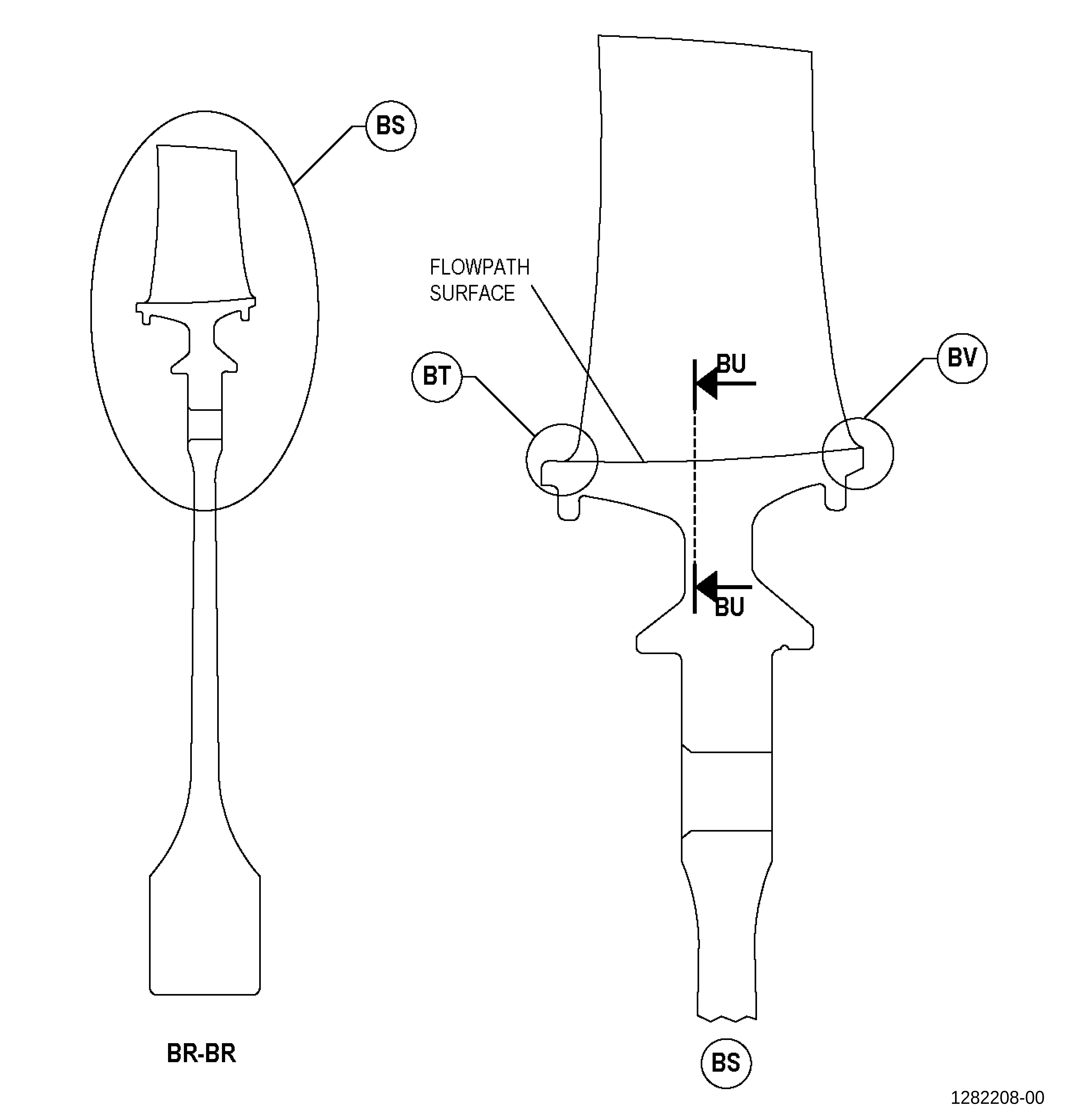
| A. | This procedure gives instructions to repair the high pressure compressor rotor (HPCR) stage 5 blisk (blisk) by blending. Refer to Figure 901. |
| B. | The following maximum repairable limits apply to this repair: |
| NOTE: |
|
| NOTE: |
|
| (4) | Visual Inspection. |
| (f) | Do an inspection of the flowpath surface of the blisk for: |
| 1 | Nicks, dents, pits, and scratches: |
| Maximum repairable limit: |
|
| C. | The subsequent table gives a list of the part numbers that are applicable to this repair. All part numbers are applicable to all paragraphs unless specified differently. |
|
|||||||||||||||||||||||
| D. | Proprietary/Complex Process Statement. |
| (1) | None. |
| 2. | Tools, Equipment, and Materials. |
| NOTE: |
|
| A. | Tools and Equipment. |
| (1) | Special Tools. None. |
| (2) | Standard Tools and Equipment. None. |
| (3) | Locally Manufactured Tools. None. |
| B. | Consumable Materials. |
| C. | Referenced Procedures. |
|
| D. | Expendable Parts. None. |
| E. | SPD Information. None. |
| F. | Special Solutions. None. |
| G. | Test Specimens. None. |
| 3 . | Dimensional Information. |
| Subtask 72-31-44-220-056 |
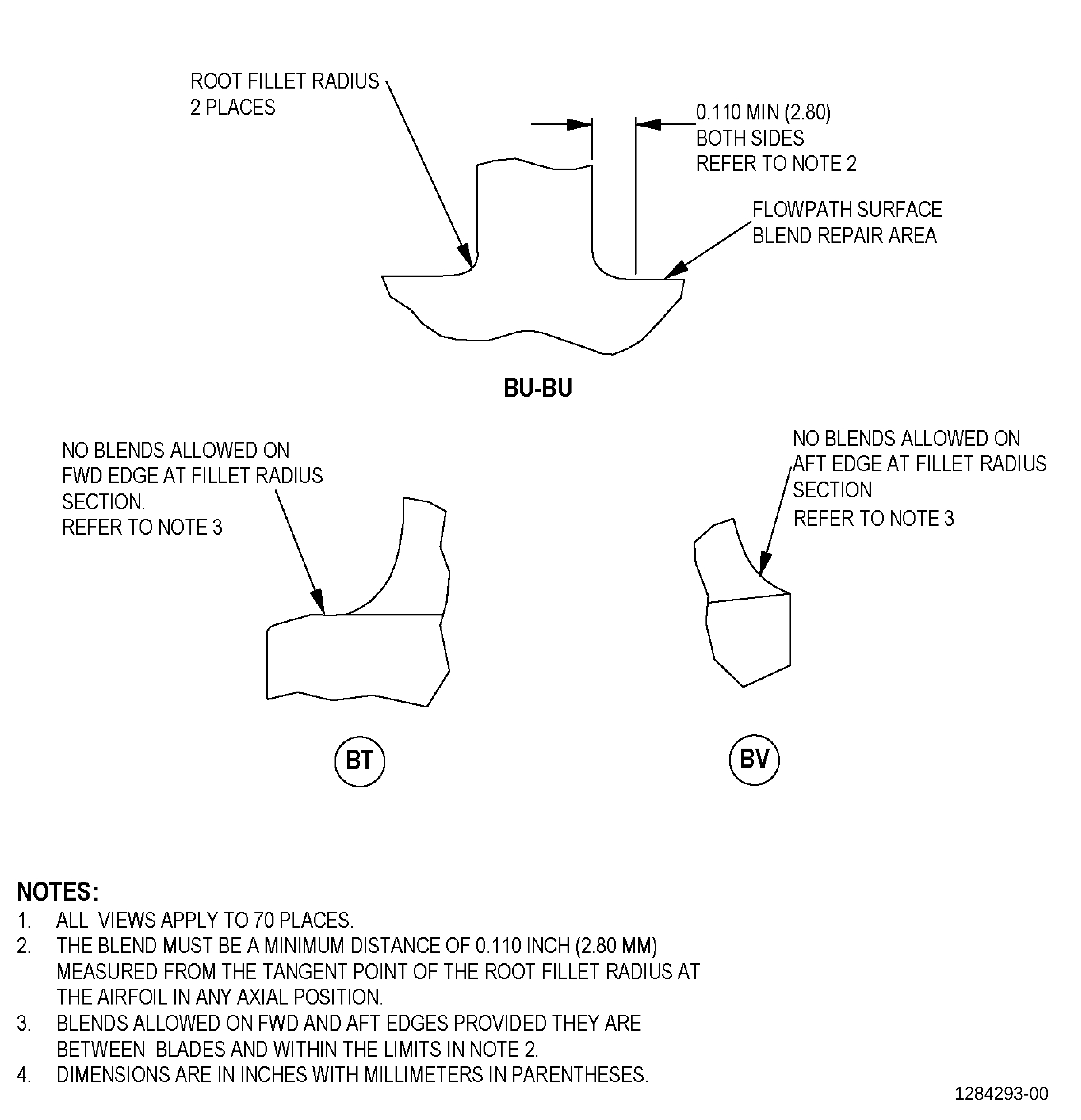
| A. | Refer to Figure 901 for specified dimensions and locations. |
| NOTE: |
|
| 4 . | Setup Information. |
| None. |
| 5 . | Procedure. |
| Subtask 72-31-44-100-002 |
| A. | Clean the blisk. Refer to TASK 72-31-44-100-801 (72-31-44, CLEANING 001). |
| Subtask 72-31-44-200-001 |
| B. | Do an inspection of the blisk. Refer to TASK 72-31-44-200-801 (72-31-44, INSPECTION 001). |
| Subtask 72-31-44-350-003 |
| C. | Blend the blisk damaged area. Refer to TASK 70-42-00-350-002 (BLENDING AND REMOVAL OF HIGH METAL PROCEDURES), Figure 901, and as follows: |
| CAUTION: |
|
| (1) | Blend the minimum quantity of parent material to a maximum depth of 0.005 inch (0.12 mm) to remove the damage fully. Use a 10:1 width-to-depth blend ratio. |
| (2) | If you cannot remove the damage at the maximum repairable limit, or if the blends extended beyond the repairable area, you cannot repair the blisk with this procedure. |
| Subtask 72-31-44-110-009 |
| D. | Etch the blisk repaired area. Refer to TASK 70-24-00-110-033 (ETCHING PROCEDURES FOR FLUORESCENT-PENETRANT INSPECTION), TASK 70-24-01-110-034 (SWAB ETCHING PROCEDURE), and as follows: |
| (1) | Use Class C etchant. |
| Subtask 72-31-44-200-002 |
| E. | Do an inspection of the blisk repaired area. Refer to TASK 70-32-00-200-002 (INDIRECT INSPECTION METHODS), TASK 70-32-02-230-001 (FLUORESCENT PENETRANT INSPECTION), and as follows: |
| (1) | Use Class G penetrant. |
| (2) | Refer to TASK 72-31-44-200-801 (72-31-44, INSPECTION 001), for acceptability limits. |
| Subtask 72-31-44-380-050 |
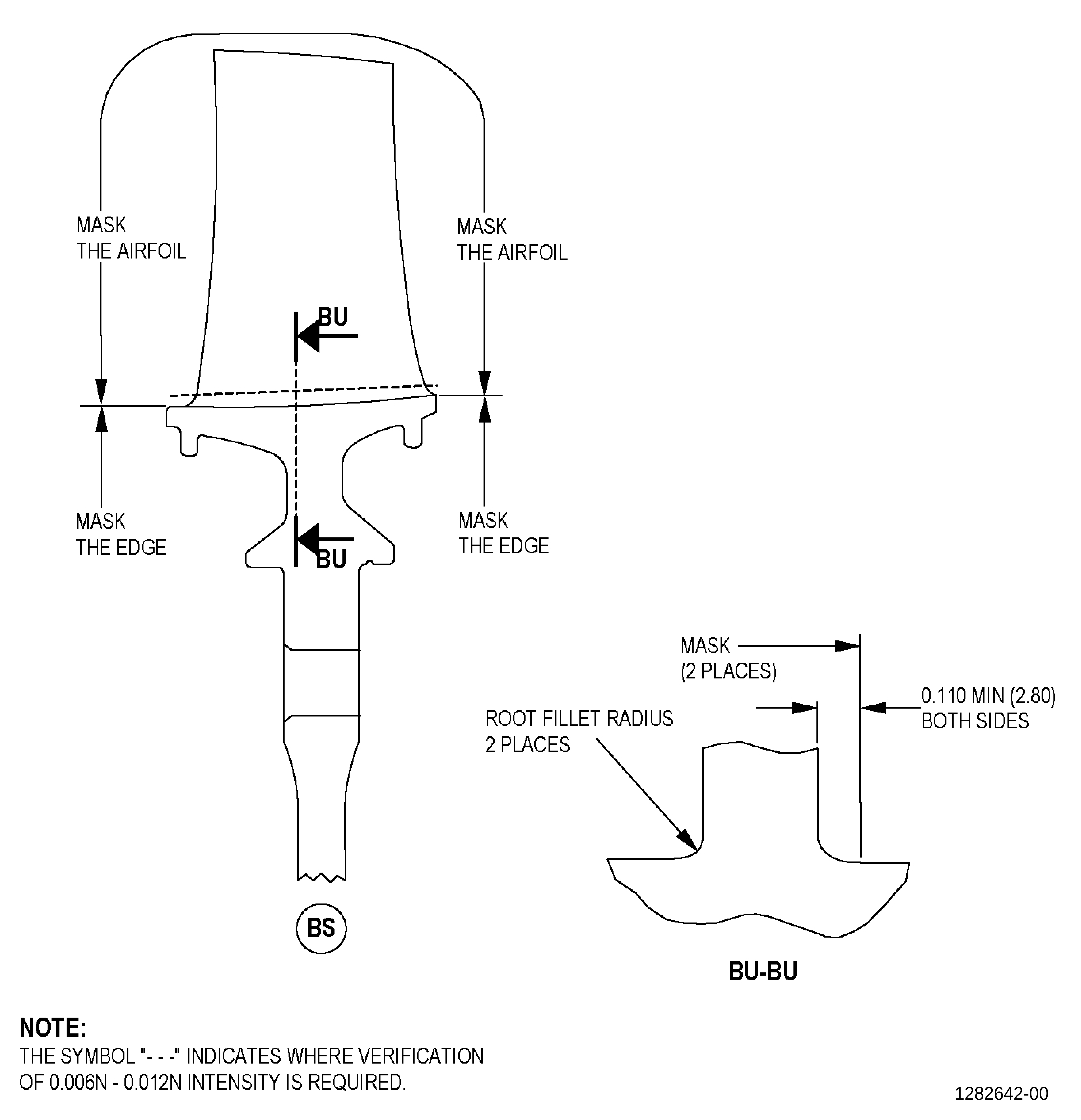
| F. | Peen the blisk repaired area. Refer to TASK 70-47-01-380-016 (SHOTPEENING), Figure 902, and as follows: |
| (1) | Apply C10-012 masking tape to the areas that you will not peen. |
| (2) | Use Type N C10-205 almen test strips. |
| (3) | Use S110 C04-271 cast steel shot. |
| (4) | Peen area to an intensity of 0.006N-0.012N. |
| (5) | Intensity verification is necessary in the blisk repaired area. Use a scrap part or simulative fixture. |
| (6) | A minimum coverage of 125 percent is necessary. |
| (7) | Overspray is not permitted. |
| (8) | Remove the plastic tape from the blisk. |
| (9) | Remove the blisk from the holding fixture. |
| Subtask 72-31-44-350-004 |
| WARNING: |
|
| G. | Polish the blisk blended areas as follows: |
| (1) | Use a C10-187 abrasive cloth or equivalent with grit size 150 or higher. |
| (2) | The surface finish must be 32 microinches (0.8 micrometer) or better. |
| Subtask 72-31-44-100-003 |
| H. | Clean the blisk. Refer to TASK 72-31-44-100-801 (72-31-44, CLEANING 001). |
| Subtask 72-31-44-200-003 |
| I. | Do a final inspection of the blisk repaired areas. Refer to TASK 72-31-44-200-801 (72-31-44, INSPECTION 001). |