| GENX-1B ENGINE MANUAL | Dated: 04/07/2025 | |
| EM 72-31-00 , DISASSEMBLY 001 | ||
| HIGH PRESSURE COMPRESSOR ROTOR ASSEMBLY - DISASSEMBLY 001 | ||
| GENX-1B ENGINE MANUAL | Dated: 04/07/2025 | |
| EM 72-31-00 , DISASSEMBLY 001 | ||
| HIGH PRESSURE COMPRESSOR ROTOR ASSEMBLY - DISASSEMBLY 001 | ||
| * * * FOR ALL |
| TASK 72-31-00-040-801 |
| 1 . | General. |
| A. | This procedure gives the instructions to disassemble the high pressure compressor (HPC) rotor assembly (15-011 , 72-30-00) (SIN 05000) or (15-012 , 72-30-00) (SIN 05000). |
| B. | Read this procedure and become familiar with the instructions and special tools before you disassemble the HPC rotor assembly. |
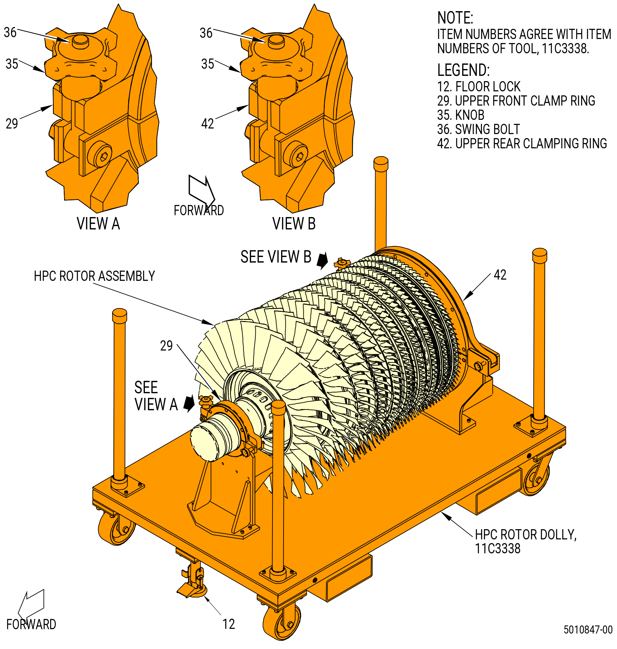
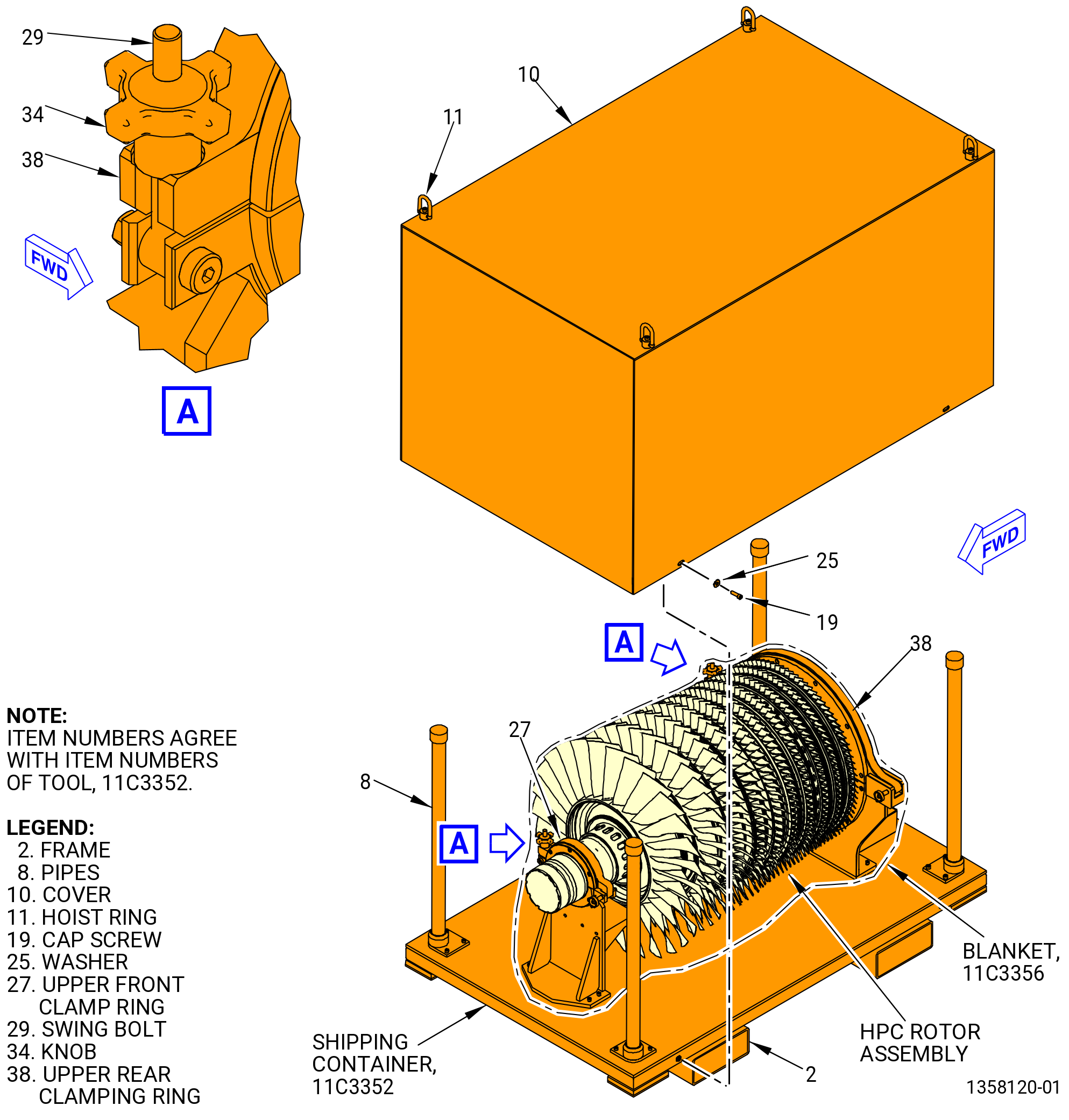
| C. | This procedure begins with the HPC rotor assembly in the 11C3338 dolly or the 11C3352 shipping container. Refer to Figure Figure 501 and Figure 502. |
| WARNING: |
|
| WARNING: |
|
| WARNING: |
|
| D. | Clean the tooling before use with C04-035 isopropyl alcohol, C04-002 Stoddard solvent, or C04-003 acetone. |
| E. | If an axisymmetric rotating part with a visible crack through the axial or radial thickness of the part feature is found during the disassembly procedure, then the mating Life Limited Part(s) (LLP) can be affected. The mating LLP must be considered not serviceable and not repairable. |
| NOTE: |
|
| NOTE: |
|
| 2 . | Tools, Equipment, and Materials. |
| NOTE: |
|
| A. | Tools and Equipment. |
| (1) | Special Tools. |
| (2) | Standard Tools and Equipment. |
|
| (3) | Locally Manufactured Tools. None. |
| B. | Consumable Materials. |
|
| C. | Referenced Procedures. |
|
| D. | Expendable Parts. None. |
| 3 . | Procedure. |
| Subtask 72-31-00-040-001 |
| A. | Remove the HPC rotor assembly from the 11C3338 dolly or the 11C3352 shipping container for disassembly. Refer to Figure 501, Figure 502, and do as follows: |
| (1) | If necessary, remove the cover (item 10) from the 11C3352 shipping container as follows. Refer to Figure 502. |
| (a) | Remove the four cap screws (item 19) and washers (item 25) from the frame (item 2). |
| (b) | Attach an overhead hoist to the hoist rings (item 11) on the cover (item 10). |
| (c) | Lift the cover (item 10) and remove from the frame (item 2). |
| (d) | Remove the 11C3356 blanket from the HPC rotor assembly. |
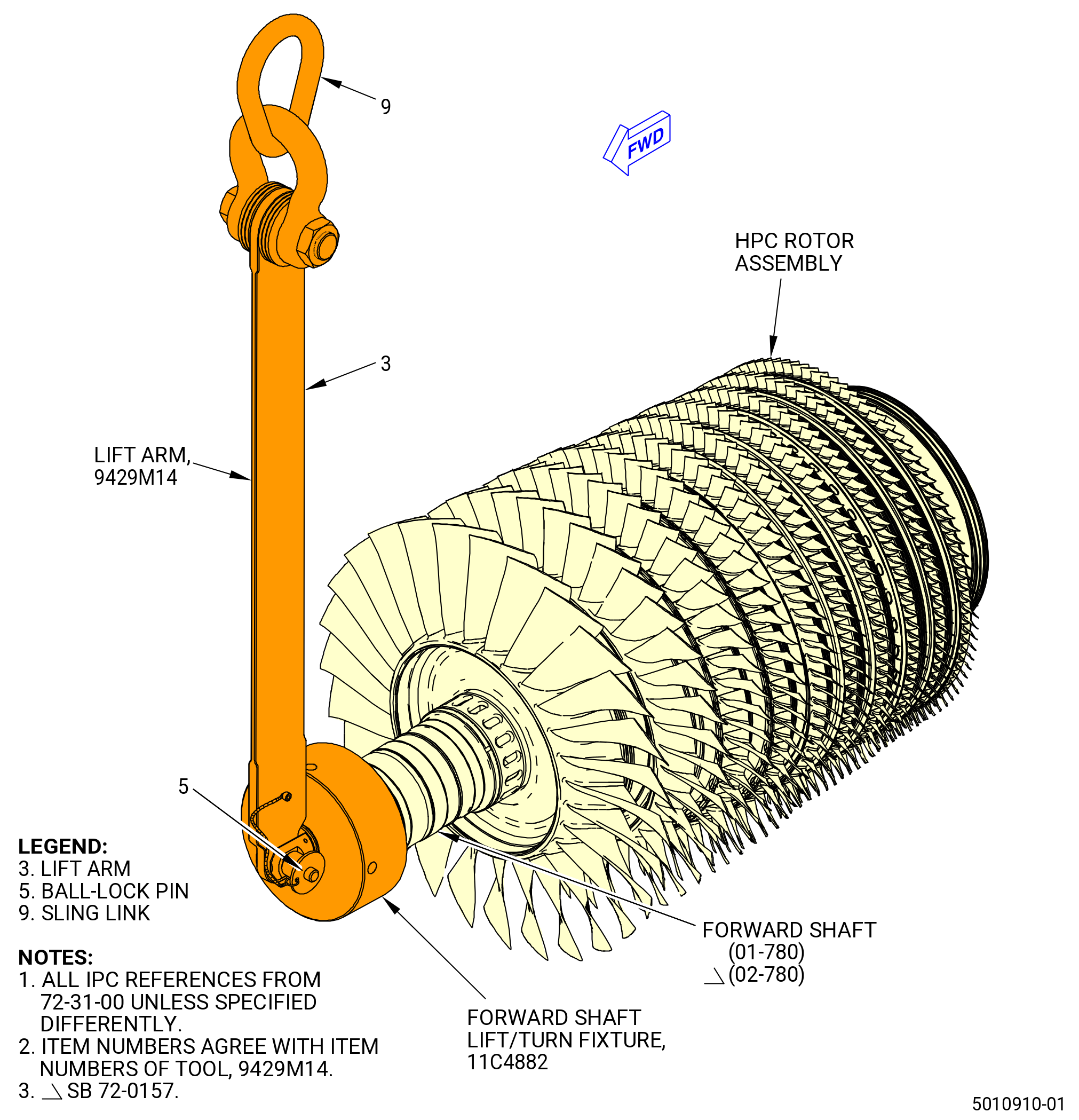
| (2) | Install the 11C4882 forward shaft lift/turn fixture on the forward shaft (01-780) (SIN 050B5) or (02-780) (SIN 050B5). Refer to Figure 503 and do as follows: |
| (a) | Thread the 11C4882 forward shaft lift/turn fixture on the threads of the forward shaft. Hand-tighten the fixture. |
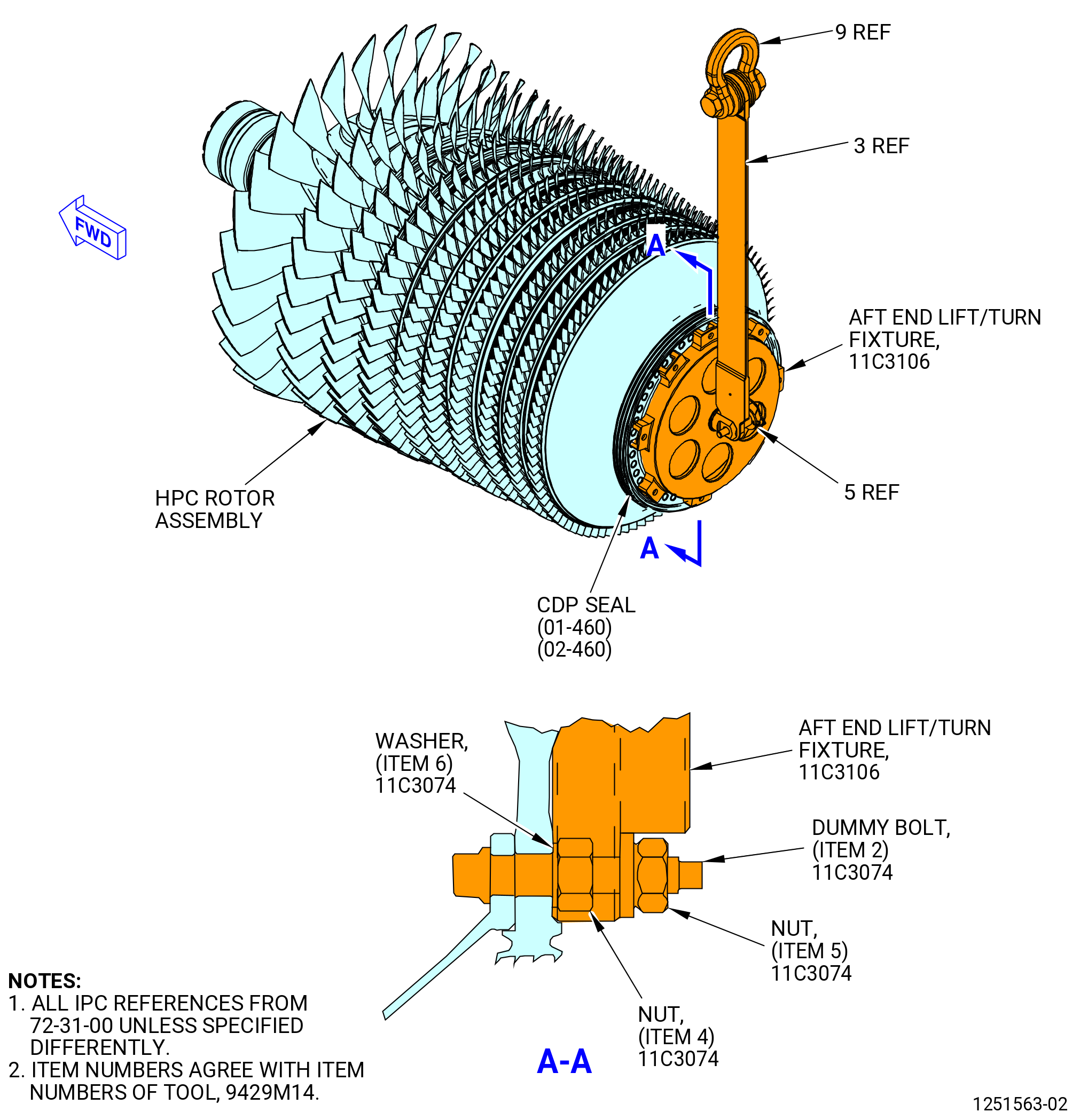
| (3) | If necessary, install the 11C3074 dummy bolt tool kit on the compressor discharge pressure (CDP) rotating seal (01-460) (SIN 050NC) or (02-460) (SIN 050NC) as follows: |
| (a) | Install the eight dummy bolts (item 2) in the CDP bolt flange on the aft end of the HPC rotor assembly. |
| NOTE: |
|
| (b) | Attach the dummy bolts (item 2) with the washers (item 6) and nuts (item 4). |
| (c) | Torque the nuts (item 4) to 100 lb in. (11.3 N.m) in a crisscross pattern. |
| Subtask 72-31-00-040-067 |
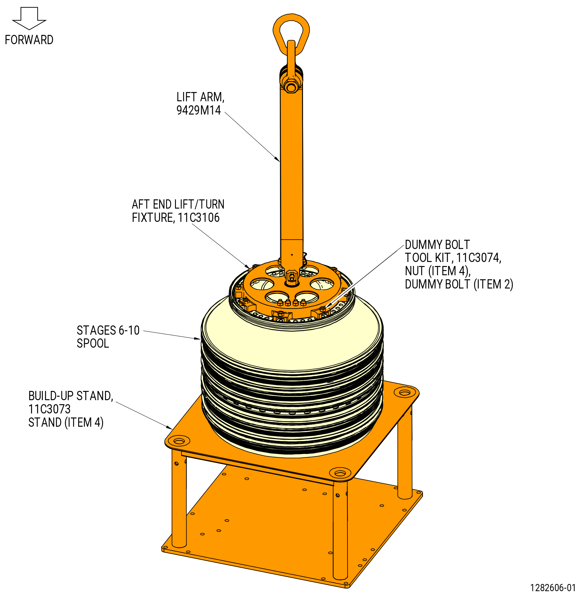
| (4) | Alternative Procedure Available. Install the 11C3106 aft end lift/turn fixture on the CDP rotating seal as follows: |
| (a) | Put the fixture on the dummy bolts (item 2) of the 11C3074 dummy bolt tool kit. |
| (b) | Attach the 11C3106 aft end lift/turn fixture with the nuts (item 5) of the 11C3074 dummy bolt tool kit and tighten in a crisscross pattern. |
| Subtask 72-31-00-040-068 |
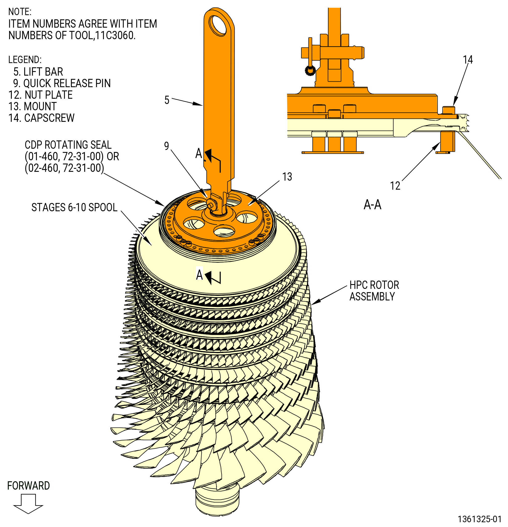
| (4).A. | Alternative Procedure. Install the 11C3060 lift/turn fixture on the CDP rotating seal. Refer to Figure 504 and do as follows: |
| (a) | Attach the four nut plates (item 12) to the stages 6-10 spool aft flange and the CDP rotating seal (01-460) (SIN 050NC) or (02-460) (SIN 050NC) with four capscrews (item 14). Make sure the center bolthole in the nut plates is 90 degrees apart on the stages 6-10 spool aft flange. |
| (b) | Attach a hoist to the lift bar (item 5). Make sure that lift bar is attached to the mount (item 13) with the quick release pin (item 9). |
| WARNING: |
|
| (c) | Operate the hoist to lift the 11C3060 lift/turn fixture, move it above the stages 6-10 spool aft flange and lower it on the flange. |
| (d) | Attach the mount (item 13) to the stages 6-10 spool aft flange and the CDP rotating seal with the capscrews (item 14). |
| (5) | Install a 9429M14 lift arm to the 11C4882 forward shaft lift/turn fixture with the ball-lock pin (item 5) of the 9429M14 lift arm. |
| (6) | Install a second 9429M14 lift arm to the 11C3106 aft end lift/turn fixture with the ball lock pin (item 5) of the 9429M14 lift arm. |
| (7) | Attach two overhead hoists to the sling link (item 9) of the 9429M14 lift arm. |
| Subtask 72-31-00-440-205 |
| (8) | Alternative Procedure Available. Remove the HPC rotor assembly from the 11C3338 dolly as follows. Refer to Figure 501. |
| (a) | Put the floor locks (item 12) of the 11C3338 dolly down to prevent movement of the dolly. |
| (b) | Loosens the knobs (item 35) at the upper front clamp ring (item 29) and upper rear clamping ring (item 42) of the 11C3338 dolly. |
| (c) | Turn the knobs (item 35) and swing bolts (item 36) 180 degrees. |
| (d) | Move the upper front clamp ring (item 29) and upper rear clamping ring (item 42) from the HPC rotor assembly. |
| Subtask 72-31-00-440-207 |
| (8).A. | Alternative Procedure. Remove the HPC rotor assembly from the 11C3352 shipping container as follows. Refer to Figure 502. |
| (a) | Loosen the knobs (item 34) at the upper front clamp ring (item 27) and upper rear clamping ring (item 38). |
| (b) | Turn the knobs (item 34) and swing bolts (item 29) 180 degrees. |
| (c) | Move the upper front clamp ring (item 27) and upper rear clamping ring (item 38) from the HPC rotor assembly. |
| Subtask 72-31-00-440-208 |
| WARNING: |
|
| (9) | Operate the two hoists to lift the HPC rotor assembly from the 11C3338 dolly or the 11C3352 shipping container. |
| (10) | Move the HPC rotor assembly away from the 11C3338 dolly or the11C3352 shipping container. |
| Subtask 72-31-00-440-209 |
| (11) | Carefully use the hoists to turn the HPC rotor assembly to the vertical position with the 11C4882 forward shaft lift/turn fixture and the shaft of the HPC rotor assembly up. |
| (12) | Remove the 9429M14 lift arm from the 11C3106 aft end lift/turn fixture. Refer to Figure 503. |
| (13) | Remove the nuts (item 5) of the 11C3074 dummy bolt tool kit from the dummy bolts (item 2). |
| Subtask 72-31-00-040-069 |
| (14) | Alternative Procedure Available. Remove the 11C3106 aft end lift/turn fixture from the dummy bolts (item 2) of the 11C3074 dummy bolt tool kit. |
| Subtask 72-31-00-040-070 |
| (14).A. | Alternative Procedure. Remove the capscrews (item 14) from the nut plates (item 12) to remove the 11C3060 lift/turn fixture from the CDP seal. |
| Subtask 72-31-00-040-030 |
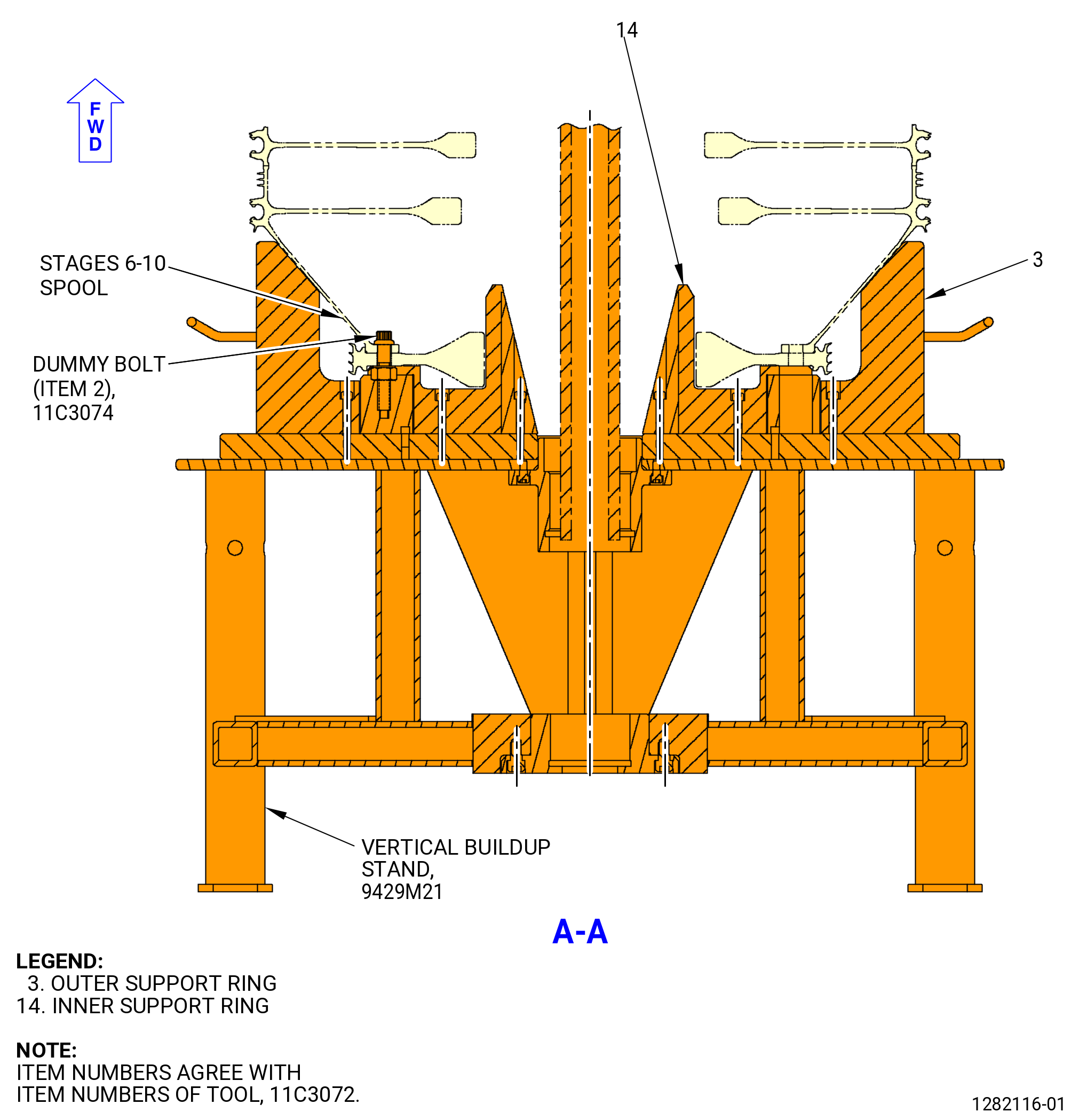
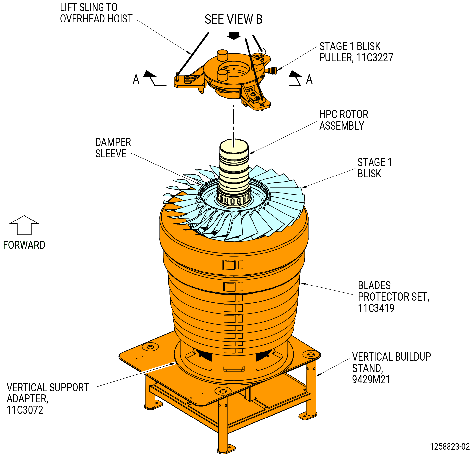
| B. | Install the HPC rotor assembly on the 11C3072 vertical support adapter. Refer to Figure 505 and do as follows: |
| NOTE: |
|
| (1) | Align the dummy bolts (item 2) of the 11C3074 dummy bolt tool kit on the HPC rotor assembly with the boltholes of the inner support ring (item 14) of the 11C3072 vertical support adapter. |
| (2) | Lower the HPC rotor assembly on the inner support ring (item 14) until the stages 6-10 spool is on the outer support ring (item 3). |
| (3) | Remove the 9429M14 lift arm from the 11C4882 forward shaft lift/turn fixture. |
| (4) | Remove the 11C4882 forward shaft lift/turn fixture from the forward shaft (01-780) (SIN 050B5) or (02-780) (SIN 050B5). If necessary, use a 0.38 inch (9.7 mm) rod to turn the fixture counterclockwise (CCW). |
| Subtask 72-31-00-040-043 |
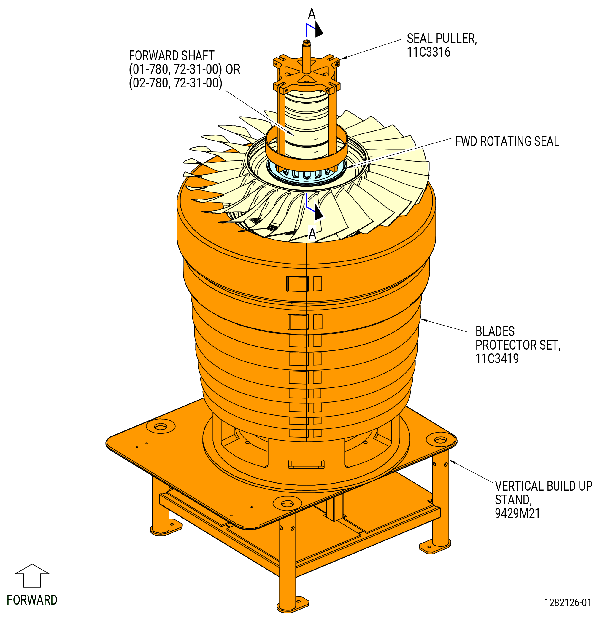
| C. | Remove the rotating seal (FWD rotating seal) (01-820) (SIN 03005) from the forward shaft (01-780) (SIN 050B5) or (02-780) (SIN 050B5) of the HPC rotor assembly. Refer to Figure 506 and do as follows: |
| (1) | If necessary, install the 11C3419 blades protector set on the HPC rotor assembly. Refer to Figure 506. |
| NOTE: |
|
| WARNING: |
|
| (2) | Use a heat gun to increase the temperature of the FWD rotating seal to 300 °F (148.9 °C). |
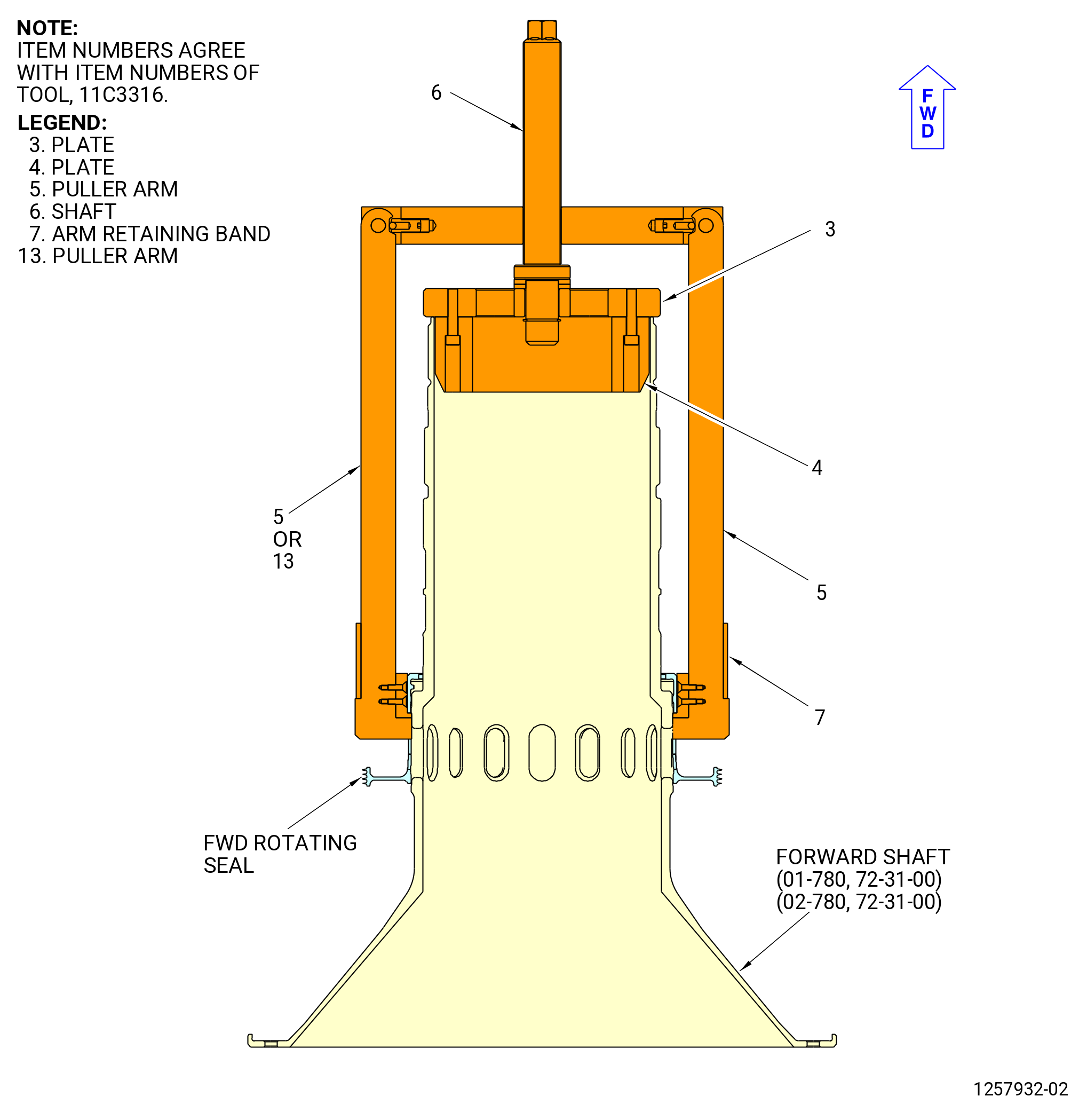
| (3) | Put the 11C3316 seal puller on the forward shaft and the FWD rotating seal as follows: |
| (a) | Turn the shaft (item 6) CCW to move the plates (item 3 and item 4) forward. |
| (b) | Put the puller arms (item 5 or item 13) on the FWD rotating seal. Attach firmly in place with the arm retaining band (item 7). |
| (4) | Turn the shaft (item 6) clockwise (CW) to remove the FWD rotating seal from the forward shaft. |
| Subtask 72-31-00-040-002 |
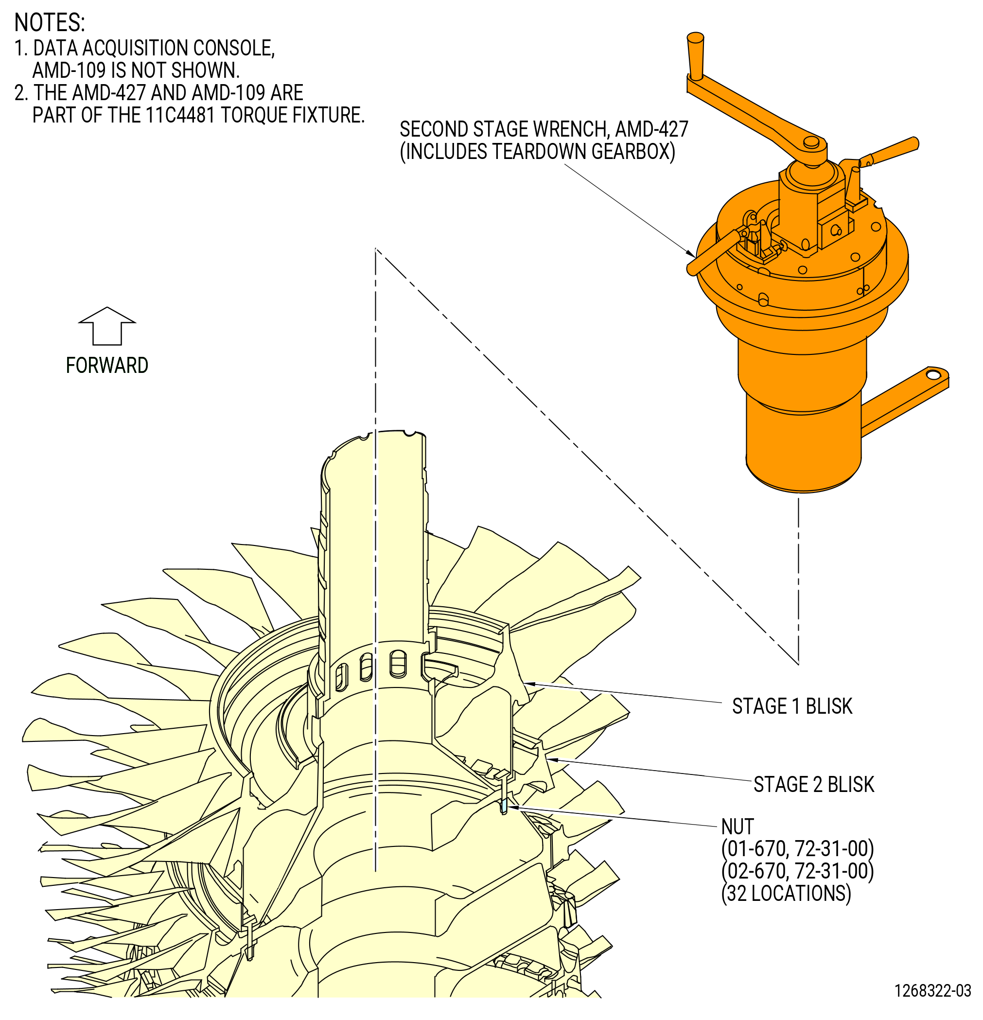
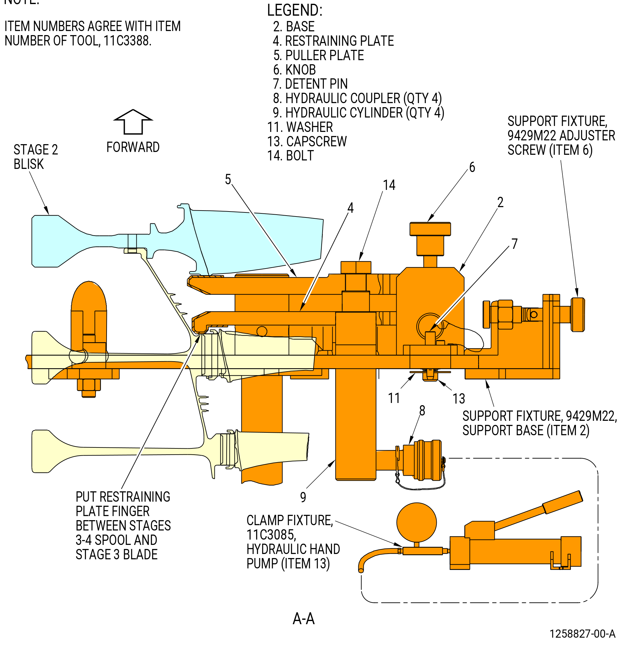
| D. | Remove the stage 1 blisk (01-800) (SIN 056A1) or (02-800) (SIN 056A1) as follows: |
| (1) | Remove the damper sleeve from the stage 1 blisk. |
| (2) | Install the 11C4481 torque fixture on the 32 nuts on the forward end of the forward shaft (01-780) (SIN 050B5) or (02-780) (SIN 050B5). Refer to the 11C4481 torque fixture instructions and Figure 507. |
| (3) | Make sure that the torque fixture is aligned with the "0" mark on the forward face of the flow path surface. |
| (4) | Remove the 32 nuts from the bolts (01-750) (SIN 050F1) or (02-750) (SIN 050F1), (01-760) (SIN 050F2) or (02-760) (SIN 050F2) that go through the stage 1 blisk, forward shaft, compressor rotor stage 2 blisk (stage 2 blisk), and stages 3-4 compressor rotor spool (stages 3-4 spool) with the 11C4481 torque fixture. Refer to the 11C4481 torque fixture instructions. |
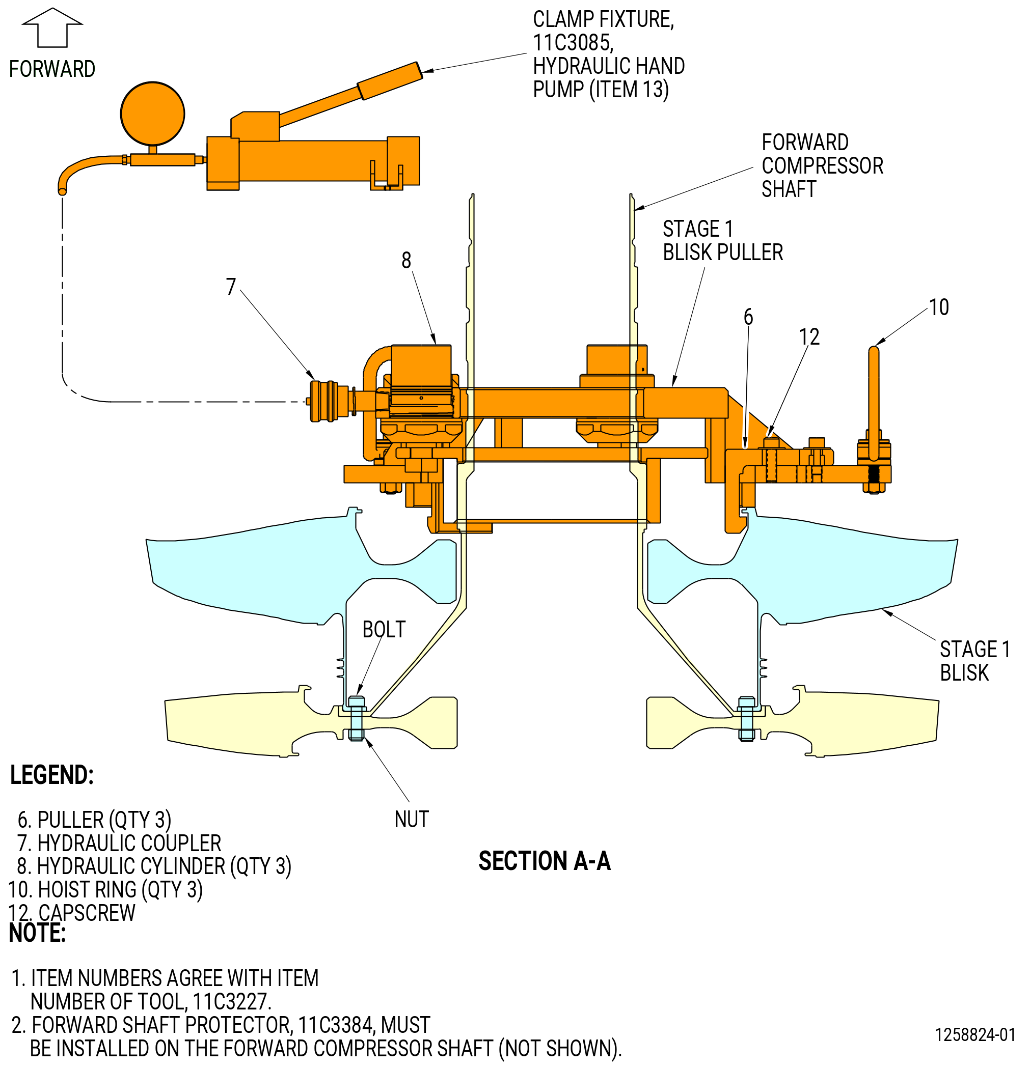
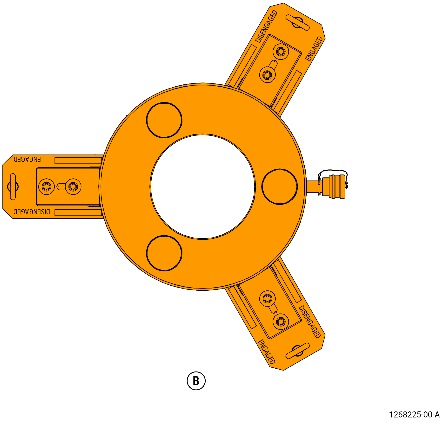
| (5) | Install the 11C3227 stage 1 blisk puller on the stage 1 blisk as follows. Refer to Figure 508. |
| (a) | Loosen the capscrews (item 12) and move the three pullers (item 6) to the DISENGAGED position. |
| (b) | Attach an overhead hoist to the three hoist rings (item 10). |
| WARNING: |
|
| (c) | Carefully lower the fixture on the stage 1 blisk of the HPC rotor assembly around the forward shaft and on the forward face of the stage 1 blisk. |
| (d) | Slide the three pullers (item 6) below the flange of the stage 1 blisk to the ENGAGED position. Tighten the capscrews (item 12) until the pullers (item 6) engage the lip on the stage 1 blisk. Make sure that the pullers (item 6) are secure. |
| (6) | Connect the hydraulic hand pump (item 13) of the 11C3085 clamp fixture to the hydraulic coupler (item 7) of the 11C3227 stage 1 blisk puller. |
| WARNING: |
|
| (7) | Apply hydraulic pressure until the stage 1 blisk disengages from the compressor forward shaft. |
| (8) | Release the hydraulic pressure from the 11C3227 stage 1 blisk puller and remove the hydraulic hand pump from the puller. |
| (9) | Loosen the capscrews (item 12) and move the pullers (item 6) to the DISENGAGED position. |
| (10) | Carefully remove the 11C3227 stage 1 blisk puller from the HPC rotor assembly with an overhead hoist. |
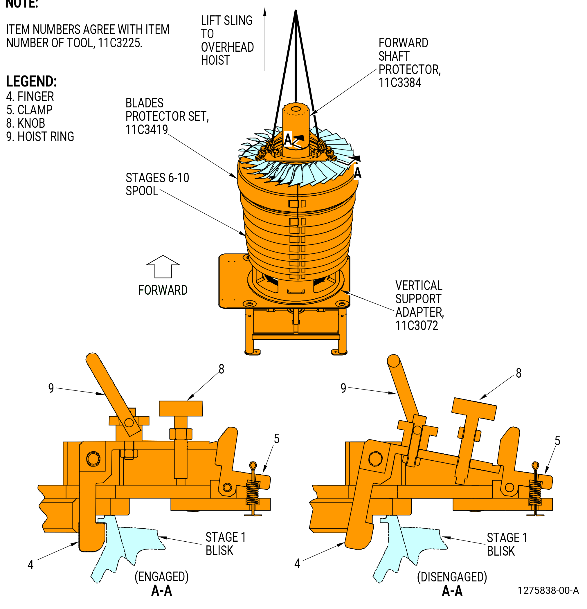
| (11) | Install the 11C3384 forward shaft protector on the forward shaft. |
| (12) | Install the 11C3225 stage 1 blisk lift fixture on the forward face of the stage 1 blisk as follows. Refer to Figure 509. |
| (a) | Turn the knobs (item 8) CW to let the clamp (item 5) engage the fingers (item 4). |
| NOTE: |
|
| (b) | Attach an overhead hoist to the three hoist rings (item 9). |
| WARNING: |
|
| (c) | Lift the fixture and carefully lower it on the stage 1 blisk of the HPC rotor assembly. |
| (d) | Attach the 11C3225 stage 1 blisk lift fixture to the stage 1 blisk as follows: |
| 1 | Move the clamp (item 5) to let the finger (item 4) go below the lip of the stage 1 blisk. |
| 2 | Turn the knobs (item 8) CCW to secure the fingers (item 4) below the lip of the stage 1 blisk. |
| (13) | Remove the bolt retainer (01-770) (SIN 050WT) from each of the 32 bolts. |
| (14) | Remove bolts (01-750) (SIN 050F1) or (02-750) (SIN 050F1) and bolts (01-760) (SIN 050F2) or (02-760) (SIN 050F2) that go through the stage 1 blisk, forward shaft, compressor rotor stage 2 blisk (stage 2 blisk), and stages 3-4 compressor rotor spool (stages 3-4 spool). |
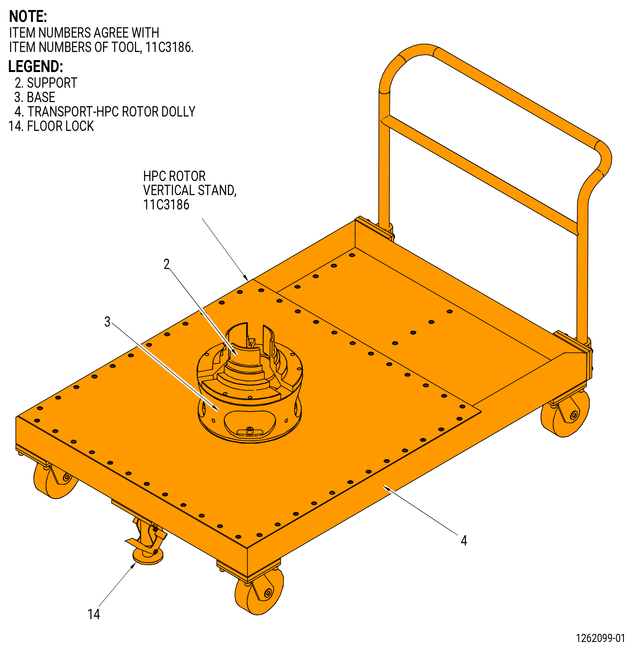
| (15) | Carefully lift the stage 1 blisk from the HPC rotor assembly. Put the stage 1 blisk on the base (item 3) of the 11C3186 HPC rotor stand. Refer to Figure 510. |
| (16) | Remove the 11C3225 stage 1 blisk lift fixture from the stage 1 blisk. |
| (17) | Make sure that the 11C3419 blades protector set is installed on the stage 1 blisk. |
| Subtask 72-31-00-040-003 |
| E. | Remove the forward shaft (01-780) (SIN 050B5) or (02-780) (SIN 050B5). Refer to Figure 511 and do as follows: |
| (1) | Remove the eight remaining self-locking nuts (01-700) (SIN 050K5) or (02-700) (SIN 050K5) from the bolts (01-710) (SIN 050F5) or (02-710) (SIN 050F5) on the stage 2 blisk. |
| CAUTION: |
|
| CAUTION: |
|
| (2) | Install four slave washers and nuts, equally spaced, on the bolts to hold the stage 2 blisk. Install the nuts until the threads are fully engaged, but leave a small clearance between the nuts and the forward shaft to minimize pop up effect. |
| NOTE: |
|
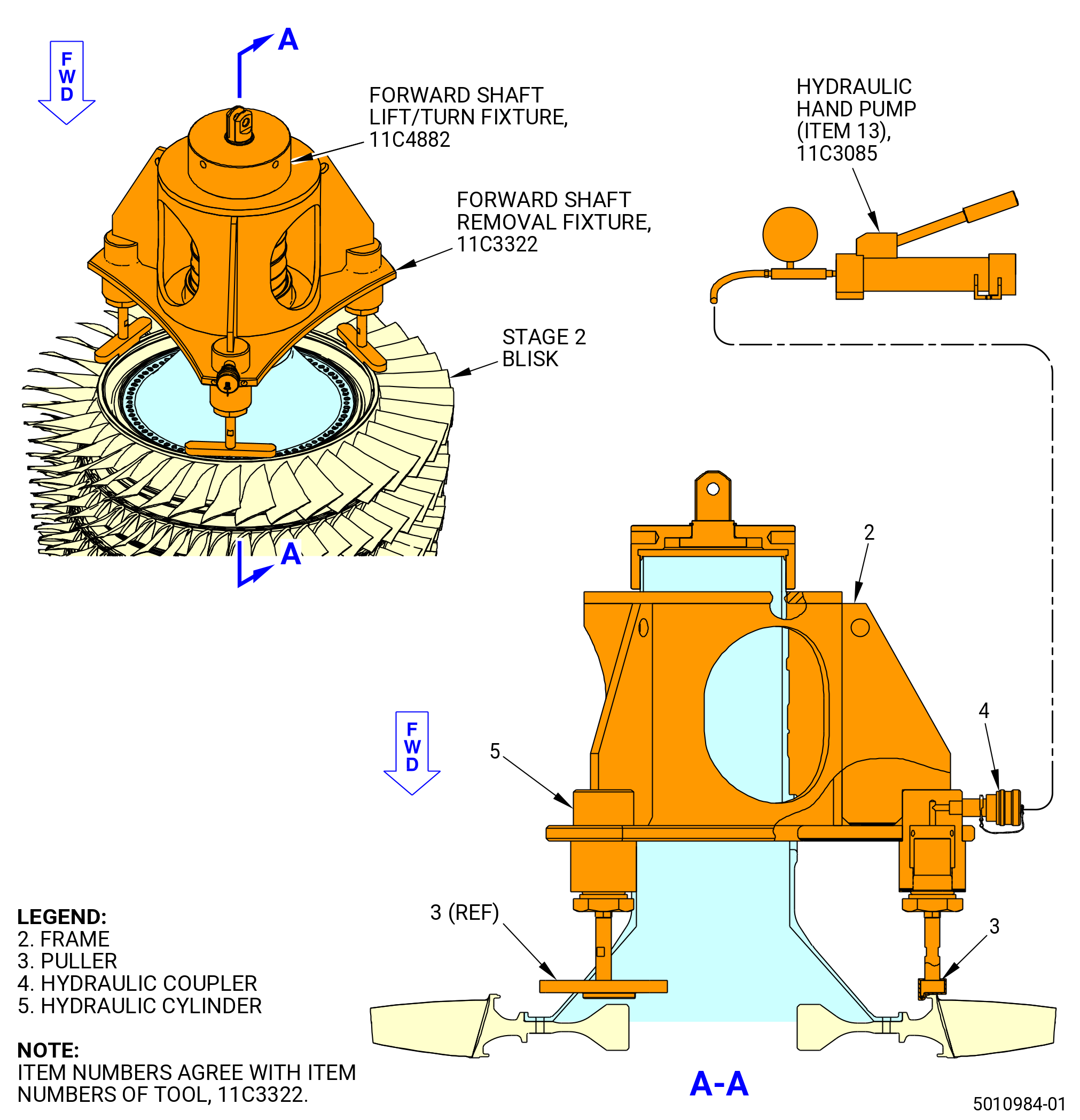
| (3) | Install the 11C3322 forward shaft removal fixture as follows: |
| (a) | Remove the 11C3384 forward shaft protector from the forward shaft. |
| (b) | Attach a lift sling to the frame (item 2) on the 11C3322 forward shaft removal fixture. |
| (c) | Lift the fixture with an overhead hoist and carefully put the fixture on the HPC rotor assembly. Make sure that the inner lip of the three pullers (item 3) are on the inward side of the bore on the stage 2 blisk. |
| (4) | Connect the hydraulic hand pump (item 13) of the 11C3085 clamp fixture to the hydraulic coupler (item 4) of the 11C3322 forward shaft removal fixture. |
| (5) | Install the 11C4882 forward shaft lift/turn fixture on the forward shaft as follows: |
| (a) | Thread the fixture CW on the threads of the forward shaft. Tighten the fixture hand-tight. |
| (b) | Use a 0.38 inch (9.7 mm) rod to tighten the fixture to the shaft. |
| Subtask 72-31-00-040-081 |
| (6) | Optional Procedure. Heating assistance. This is an optional procedure to help with the forward shaft disassembly. |
| WARNING: |
|
| CAUTION: |
|
| CAUTION: |
|
| (a) | Use a propane torch or heat gun to increase the temperature of the stage 2 blisk to a maximum of 300°F (148°C). Heat the forward rabbet and outer web area to prevent any damage to the airfoils. Make sure that you continually move the propane torch or heat gun around the stage 2 web and do not create any localized hot spots. |
| Subtask 72-31-00-040-082 |
| WARNING: |
|
| CAUTION: |
|
| (7) | Apply hydraulic pressure to the hydraulic cylinders (item 5) until the forward shaft disengages from the stage 2 blisk. |
| (8) | Remove the four slave nuts from the bolts on the HPC rotor assembly. |
| (9) | Remove the 11C4882 forward shaft lift/turn fixture from the forward shaft. If necessary, use a 0.38 inch (9.7 mm) rod to turn the fixture CCW. |
| (10) | Remove the 11C3322 forward shaft removal fixture from the HPC rotor assembly. |
| (11) | Remove the forward shaft from the HPC rotor assembly. |
| Subtask 72-31-00-040-031 |
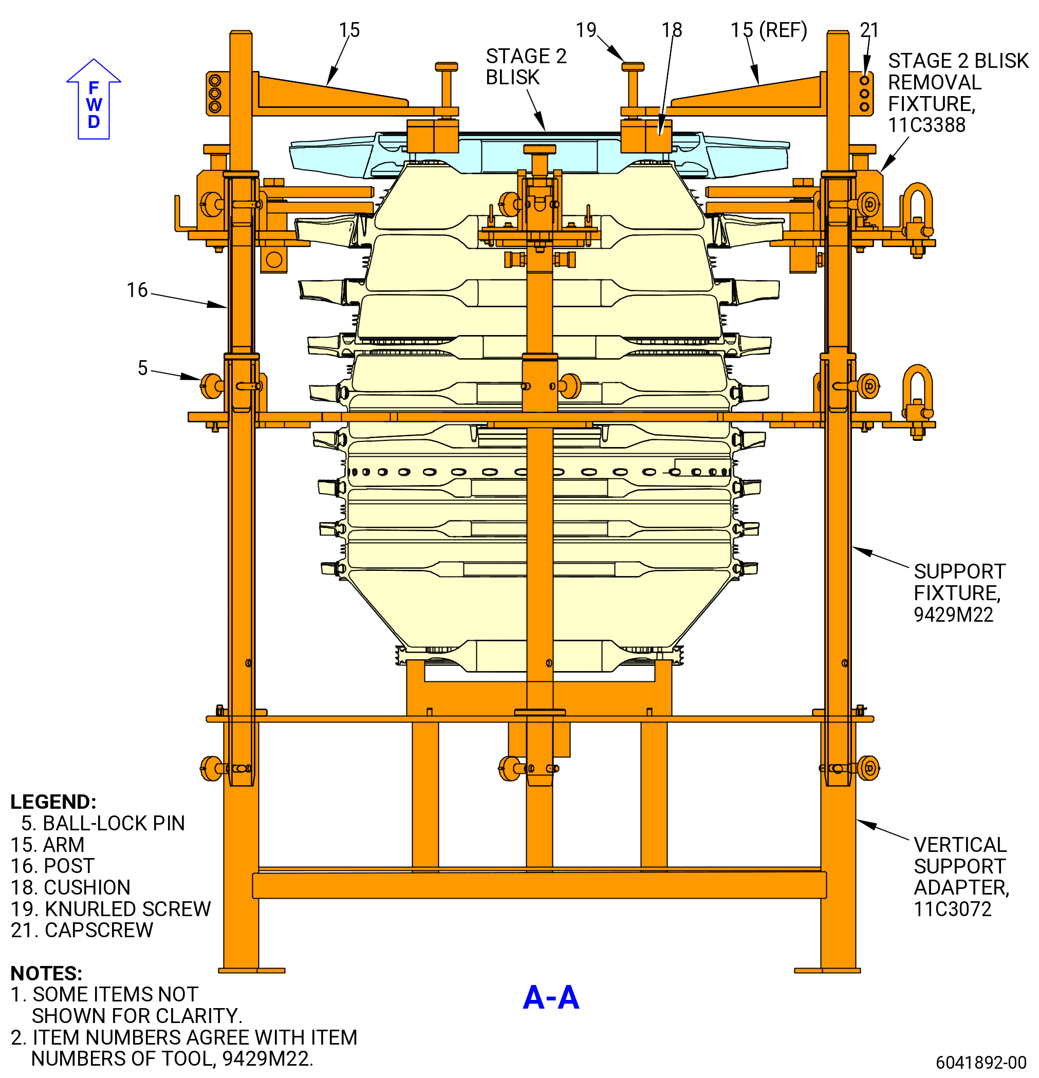
| F. | Remove the stage 2 blisk (01-740) (SIN 056A2) or (02-740) (SIN 056A2). Refer to Figure 512 and do as follows: |
| (1) | Remove the damper sleeve from the stage 2 blisk. |
| (2) | Remove the 11C3419 blades protector set from the stage 2 blisk. |
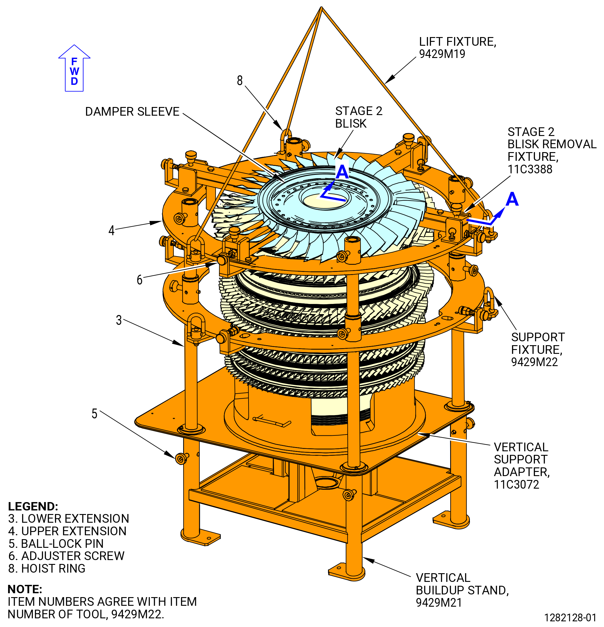
| (3) | Install the 9429M22 support fixture on the 9429M21 vertical buildup stand as follows: |
| WARNING: |
|
| (a) | Attach the 9429M19 lift fixture to the hoist rings (item 8) of the 9429M22 support fixture. |
| CAUTION: |
|
| (b) | Carefully lift the fixture and install on the 9429M21 vertical buildup stand. |
| (c) | Align the four lower extensions (item 3) of the 9429M22 support fixture with the four corner holes of the 9429M21 vertical buildup stand. |
| (d) | Secure the 9429M22 support fixture to the stand with the ball-lock pins (item 5). |
| (e) | Remove the 9429M19 lift fixture from the 9429M22 support fixture. |
| (4) | Install the 11C3388 stage 2 blisk removal fixture on the stage 2 blisk and the stages 3-4 compressor rotor spool (stages 3-4 spool) as follows. Refer to Figure 512. |
| CAUTION: |
|
| (a) | Install the base (item 2) of the 11C3388 stage 2 blisk removal fixture at the slots of the support base (item 2) of the 9429M22 support fixture. Install the detent pins (item 7). |
| CAUTION: |
|
| (b) | Alternately turn the adjuster screws (item 6) of the 9429M22 support fixture and the knobs (item 6) of the 11C3388 stage 2 blisk removal fixture. Turn until the 11C3388 stage 2 blisk removal fixture touches the forward side of the stage 3 of the stages 3-4 spool. |
| (c) | Carefully install the four puller plates (item 5) and the restraining plates (item 4) between the stage 2 blisk and stage 3 of the stages 3-4 spool. |
| (d) | Align the puller plates (item 5) and restraining plates (item 4) with the hydraulic cylinder (item 9) shafts and attach them with the bolts (item 14). |
| (e) | Make sure that the interface on the forward side of stage 3 of the stages 3-4 spool and the aft side of the stage 2 blisk are the same at the four locations for the puller plates (item 5) and restraining plates (item 4). |
| CAUTION: |
|
| CAUTION: |
|
| (5) | Install four slave washers and nuts, equally spaced, on the bolts in the stage 2 blisk. Install the nuts until the threads are engaged, but leave a small clearance between the nuts and the stage 2 blisk to minimize pop up effect. The slave nuts will prevent damage to the HPC rotor assembly if the stage 2 blisk falls when it is disengaged. |
| (a) | Before the stage 2 blisk is removed, install the posts (item 16) on the bushing of the support base and safety it with the ball-lock pin (item 5). |
| (b) | Install the subassembly of the arm (item 15) and make sure that the knurled screw (item 19) are fully retracted, then leave a gap of half inch between the bottom of the cushion (item 18) and the surface of the blisk. Tighten the capscrews (item 21) to 10 lb ft (13.55 Nm). |
| (c) | Lower the cushion up to touch the top surface of the stage 2 blisk with the knurled screws (item 19). |
| (6) | Connect the hydraulic hand pump (item 13) of the 11C3085 clamp fixture to the four hydraulic couplers (item 8) of the 11C3388 stage 2 blisk removal fixture. |
| Subtask 72-31-00-040-083 |
| (7) | Optional Procedure. Cooling or heating assistance. There are two alternative optional procedures available to help with the stage 2 blisk disassembly. One of them is heating the stage 2 blisk web, the other is cooling the stage 3-4 spool web. It is not recommended to use both at the same time. |
| Subtask 72-31-00-040-084 |
| WARNING: |
|
| CAUTION: |
|
| CAUTION: |
|
| (a) | Alternative Procedure Available. Use a propane torch or heat gun to increase the temperature of the stage 2 blisk to a maximum of 300°F (148°C). Heat the web area to prevent any damage to the airfoils. Make sure that you continually move the propane torch or heat gun around the stage 2 web and do not create any localized hot spots. |
| Subtask 72-31-00-040-085 |
| WARNING: |
|
| WARNING: |
|
| (a).A. | Alternative Procedure. Chill stage 3 disk of stage 3-4 spool with liquid nitrogen to approximately -22°F (-30°C). Measure temperature at the stage 2-3 spacer arm in four equally-spaced locations. |
| Subtask 72-31-00-040-086 |
| WARNING: |
|
| CAUTION: |
|
| (8) | Apply hydraulic pressure to the hydraulic cylinders (item 9) to separate the stage 2 blisk from the stages 3-4 spool. |
| (9) | Remove the hydraulic hand pump (item 13) of the 11C3085 clamp fixture from the hydraulic coupler (item 8) of the 11C3388 stage 2 blisk removal fixture. |
| Subtask 72-31-00-040-032 |
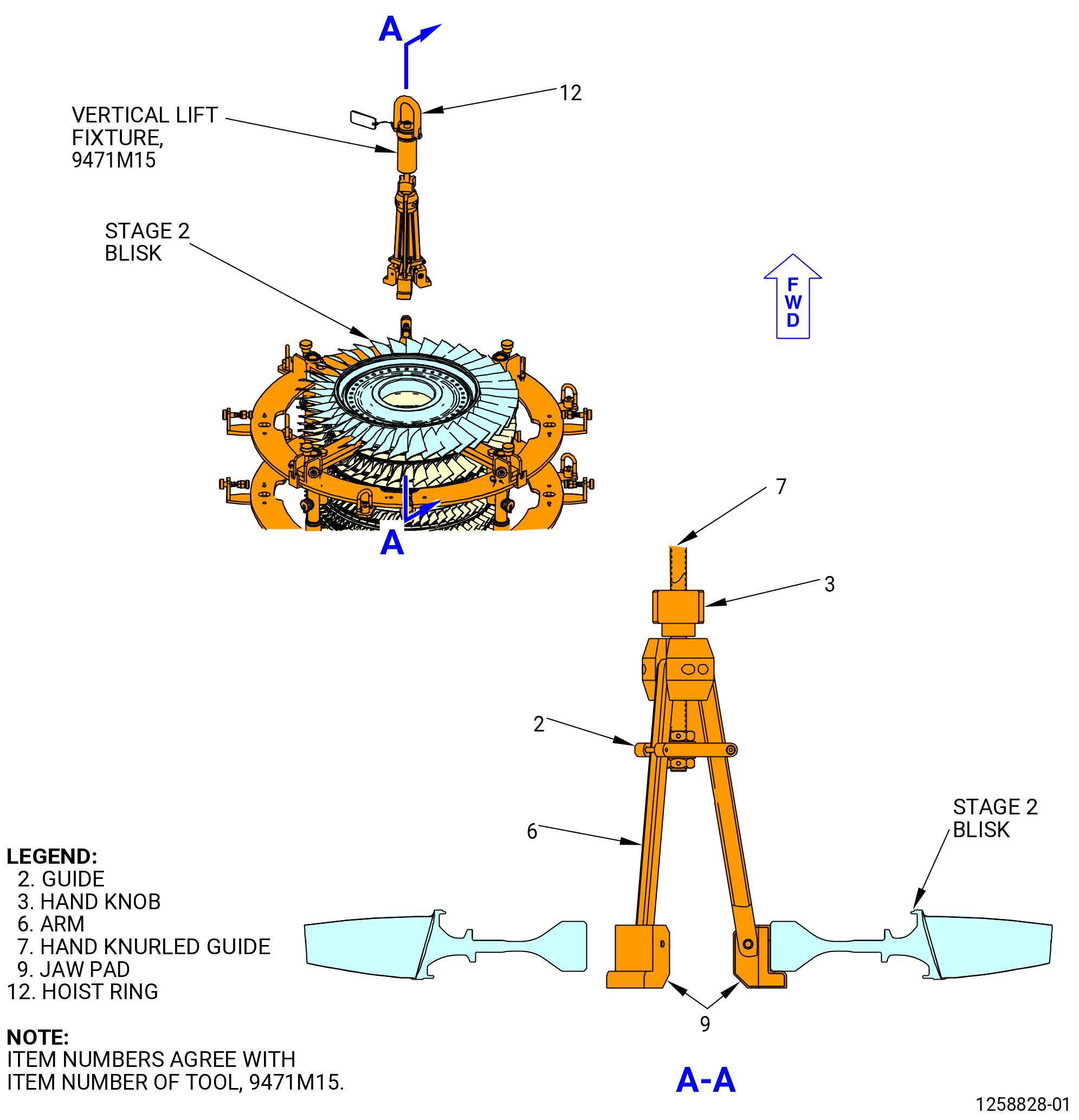
| (10) | Install the 9471M15 vertical lift fixture on the stage 2 blisk. Refer to Figure 513 and do as follows: |
| (a) | Move the 9471M15 vertical lift fixture from the hoist ring (item 12) in the vertical position. |
| (b) | Attach an overhead hoist to the hoist ring (item 12). |
| (c) | Turn the hand knob (item 3) and hand knurled guide (item 7) to let the three arms (item 6) move to the inward position. |
| WARNING: |
|
| (d) | Lift the 9471M15 vertical lift fixture and lower to the bore of the stage 2 blisk. |
| (e) | Turn the hand knob (item 3) to put the arms (item 6) outward on the bore diameter of the stage 2 blisk on the aft side. Make sure that the arms (item 6) engage correctly. |
| (f) | Tighten the hand knurled guide (item 7) and hand knob (item 3) to attach the arms (item 6). |
| (11) | Remove the four slave nuts and washers. |
| (12) | Lift the stage 2 blisk from the HPC rotor assembly and install on the base (item 3) of the 11C3186 HPC rotor stand. Refer to Figure 510. |
| (13) | Remove the 9471M15 vertical lift fixture from the stage 2 blisk. |
| (a) | Move the 9471M15 vertical lift fixture from the hoist ring (item 12) in the vertical position. |
| (14) | Install the 11C3419 blades protector set on the stage 2 blisk. |
| (15) | Remove the 11C3388 stage 2 blisk removal fixture from the stages 3-4 spool as follows. Refer to Figure 512. |
| (a) | Remove the bolts (item 14) from the hydraulic cylinders (item 9), puller plates (item 5), and restraining plates (item 4). |
| (b) | Remove the puller plates (item 5) and restraining plates (item 4) from the forward side of the stages 3-4 spool. |
| (c) | Turn the adjuster screws (item 6) of the 9429M22 support fixture and the knobs (item 6) of the 11C3388 stage 2 blisk removal fixture to move the 11C3388 stage 2 blisk removal fixture away from the fixture/assembly. |
| (d) | Remove the screws (item 13), washers (item 11), and detent pins (item 7). |
| (e) | Remove the 11C3388 stage 2 blisk removal fixture from the 9429M22 support fixture. |
| Subtask 72-31-00-040-004 |
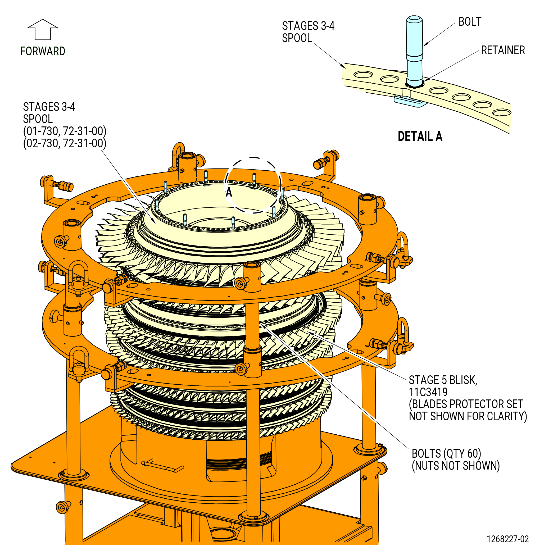
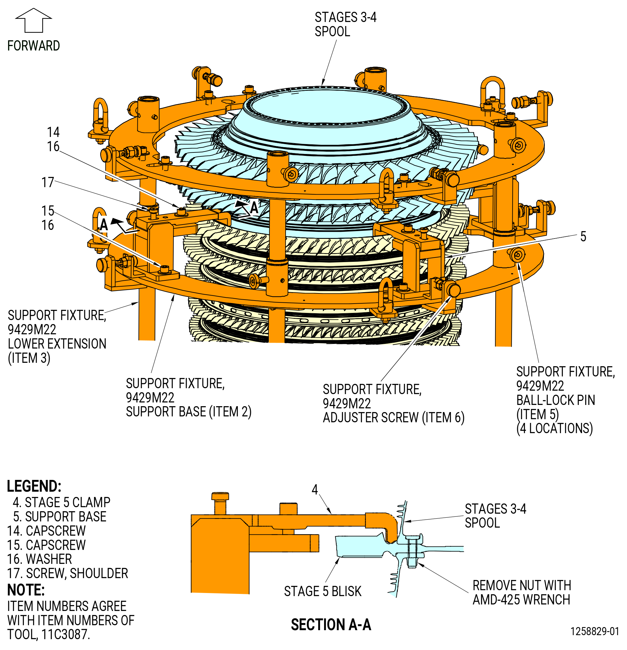
| G. | Remove the stages 3-4 spool (01-730) (SIN 050B4) or (02-730) (SIN 050B4) from the stage 5 blisk as follows: |
| (1) | Remove the eight retainers and bolts remaining from the stages 3-4 spool. Refer to Figure 514. |
| (2) | Install the 11C4481 torque fixture on the 60 nuts on the forward flange of the stages 3-4 spool. Refer to the instructions for the 11C4481 torque fixture. |
| (3) | Make sure that the torque fixture is aligned with the "0" mark on the forward face of the flow path surface. |
| (4) | Remove the 60 nuts from the bolts on the stage 5 blisk and the stages 3-4 spool with the 11C4481 torque fixture. Refer to the 11C4481 torque fixture instructions. |
| (5) | If necessary, remove the 11C3419 blades protector set from the stage 5 blisk. |
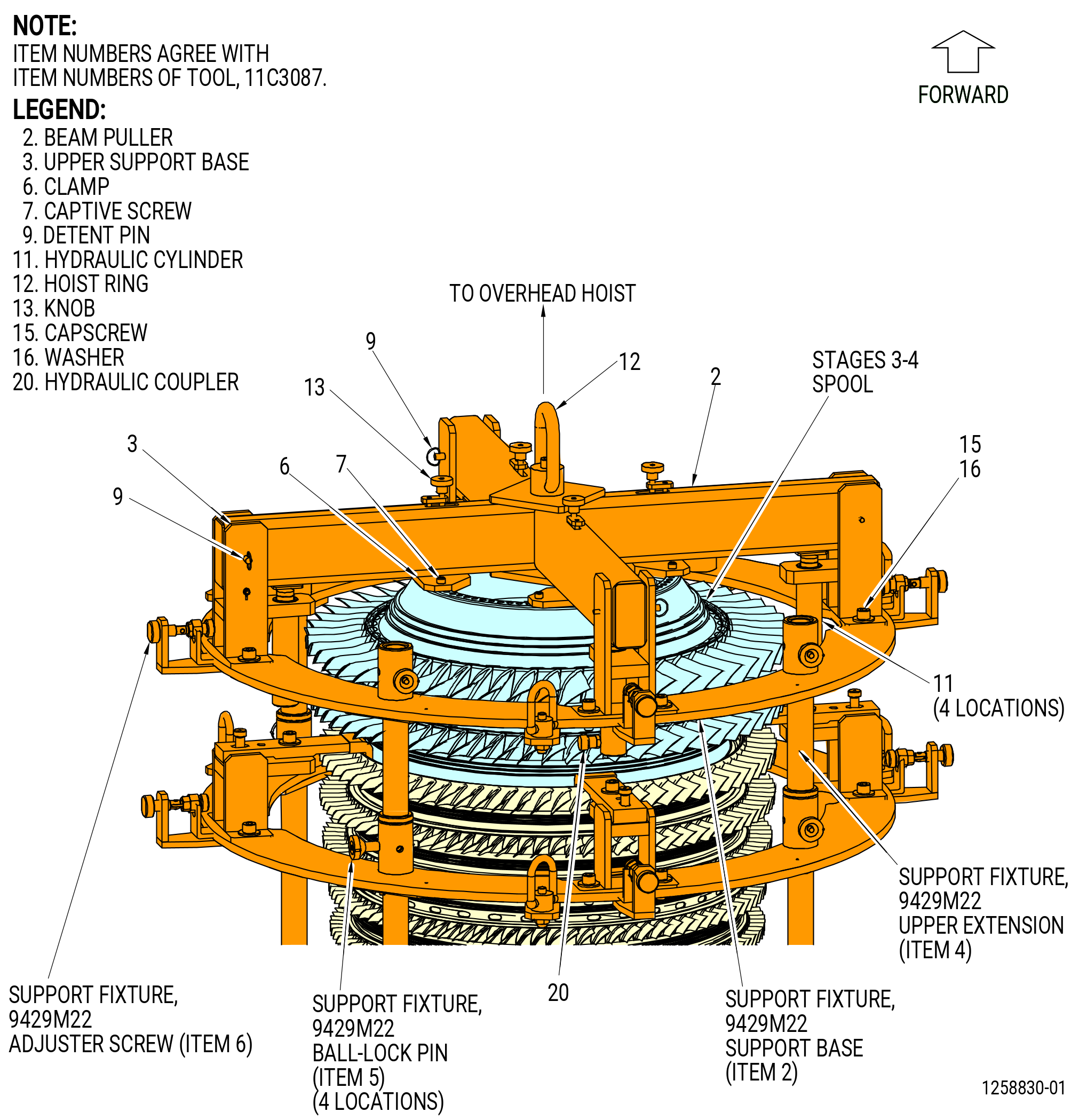
| (6) | Install the 11C3087 removal fixture as follows. Refer to Figure 515. |
| (a) | Turn the eight adjuster screws (item 6) of the 9429M22 support fixture on the support base (item 2) to the up position. |
| (b) | Remove the capscrew (item 14) and the washer (item 16) of the 11C3087 removal fixture from the stage 5 clamp (item 4) and install in the STORAGE BOLT bolthole on the clamp. |
| (c) | Lift the stage 5 clamp (item 4) and turn it 90 degrees on the shoulder screw (item 17). |
| CAUTION: |
|
| (d) | Install the four support bases (item 5) of the 11C3087 removal fixture on the support base (item 2) on the lower extension (item 3) of the 9429M22 support fixture. Attach with the capscrews (item 15) and washers (item 16) of the 11C3087 removal fixture. Do not tighten the capscrews (item 15). |
| (e) | Carefully lift the stage 5 clamp (item 4) and turn the clamp on the stage 5 blisk. Use the adjuster screw (item 6) of the 9429M22 support fixture to adjust the stage 5 clamp (item 4) of the 11C3087 removal fixture in the correct position on the stage 5 blisk. Make sure that the clamp finger is in the slot of the stage 5 blisk. |
| (f) | Remove the capscrew (item 14) and the washer (item 16) from the STORAGE BOLT bolthole and secure the stage 5 clamp (item 4) to the support base (item 5). Tighten the capscrew (item 14) to secure the stage 5 clamp (item 4). |
| (g) | Tighten the capscrew (item 15) to secure the support base (item 5). |
| (h) | Make sure that the jaws of the clamp (item 6) are inward. If necessary, turn the knob (item 13) to put the clamp inward. |
| (i) | Attach the four upper support bases (item 3) to the support base (item 2) on the upper extension (item 4) of the 9429M22 support fixture. Attach with the capscrews (item 15) and washers (item 16) of the 11C3087 removal fixture. Do not tighten the capscrews. |
| WARNING: |
|
| CAUTION: |
|
| (j) | Attach an overhead hoist to the hoist ring (item 12). Operate the hoist to install the beam puller (item 2) into the upper support bases (item 3). The four clamps (item 6) will be on the flange of the stages 3-4 spool. |
| (k) | Align the upper support base (item 3) with the beam puller (item 2) and install the detent pin (item 9). Turn the four adjuster screws (item 6) of the 9429M22 support fixture upper extension (item 4) to align the pin holes. |
| (l) | Tighten the capscrews (item 15) of the 11C3087 removal fixture to secure the upper support base (item 3). |
| (m) | Turn the clamps (item 6) with the knob (item 13) to put the clamps outward on the stage 3-4 spool forward flange and attach with captive screws (item 7). |
| (7) | Remove the four ball-lock pins (item 5) of the 9429M22 support fixture from the lower extension post. |
| (8) | Connect the hydraulic hand pump (item 13) of the 11C3085 clamp fixture to the four hydraulic couplers (item 20) of the 11C3087 removal fixture at four locations. |
| WARNING: |
|
| (9) | Apply hydraulic pressure to the hydraulic cylinders (item 11) until the stages 3-4 spool disengages from the stage 5 blisk. |
| (10) | Disconnect the hydraulic hand pump (item 13) of the 11C3085 clamp fixture from the hydraulic coupler (item 20) of the 11C3087 removal fixture. |
| (11) | Remove the capscrews (item 15) and the washers (item 16) that attach the upper support bases (item 3) of the 11C3087 removal fixture to the upper extension (item 4) of the 9429M22 support fixture. |
| (12) | Remove the detent pins (item 9) of the 11C3087 removal fixture from the upper support base (item 3). |
| (13) | Remove the upper support base (item 3), hydraulic cylinders (item 11), and hydraulic couplers (item 20) of the 11C3087 removal fixture. |
| (14) | Lift and remove the stages 3-4 spool from the HPC rotor assembly with the 11C3087 removal fixture. |
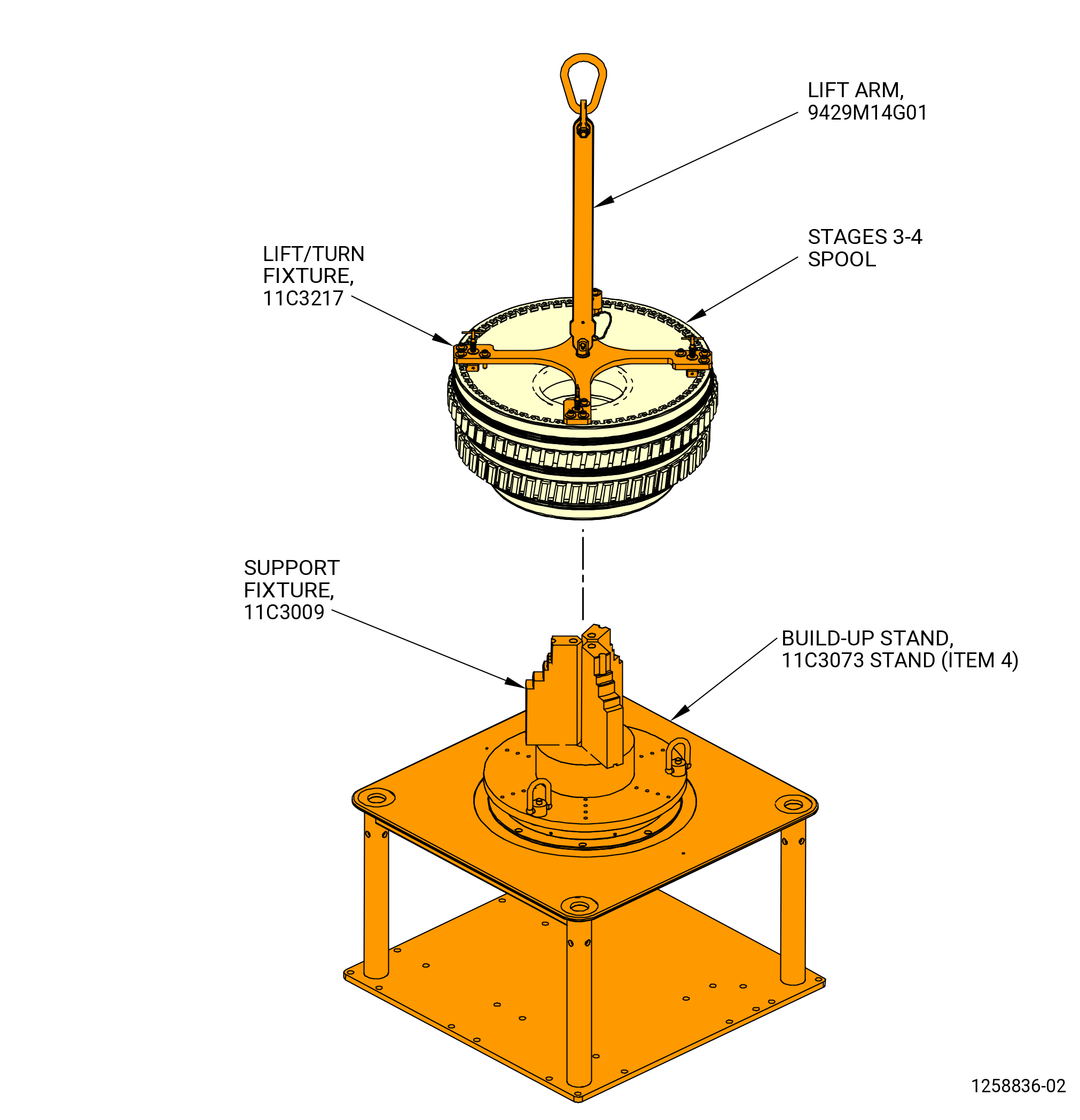
| (15) | Put the stages 3-4 spool on the 11C3009 support fixture installed on the stand (item 4) of the 11C3073 build-up stand. Refer to Figure 516. |
| (16) | Remove the 11C3087 removal fixture from the stages 3-4 spool. |
| (17) | Remove the subassembly of the arm (item 15) and post (item 16). Refer to Figure 512. |
| (18) | Remove the 11C3087 removal fixture from the support base (item 2) on the lower extension (item 3) of the 9429M22 support fixture as follows: |
| CAUTION: |
|
| (a) | Remove the capscrews (item 14) of the 11C3087 removal fixture and washers (item 16) from the stage 5 clamp (item 4). Put the capscrews and washers in the STORAGE BOLT bolthole on the clamp. |
| (b) | Carefully lift the stage 5 clamp (item 4) from the stage 5 blisk and turn 90 degrees away from the stage 5 blisk. |
| (c) | Remove the four support bases (item 5) of the 11C3087 removal fixture from the support base (item 2) on the lower extension (item 3) of the 9429M22 support fixture. |
| (19) | Use a three-legged sling to remove the support base (item 2) on the upper extension (item 4) of the 9429M22 support fixture from the support base (item 2) on the lower extension (item 3). |
| Subtask 72-31-00-040-033 |
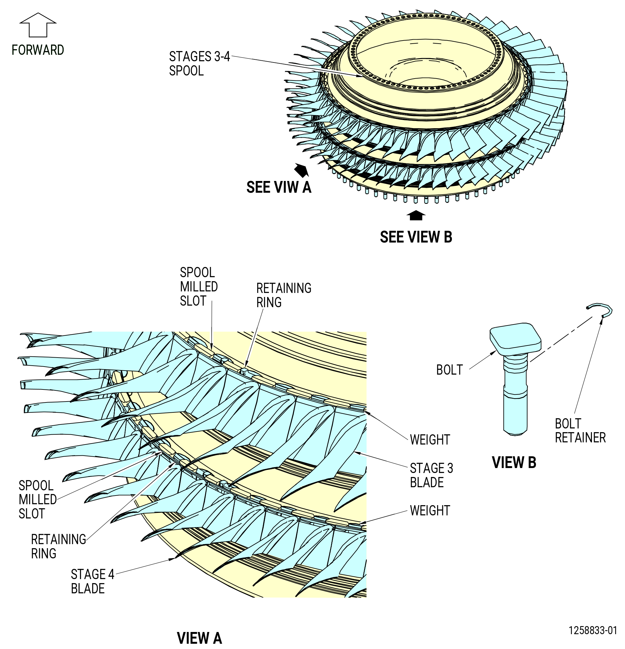
| H. | Remove the stage 3 compressor rotor blades (stage 3 blades) and stage 4 compressor rotor blades (stage 4 blades) from the stages 3-4 spool as follows. Refer to Figure 517. |
| (1) | Find the milled tab on the forward side of the stage 3 and the stage 4 spool slots. |
| (2) | Use a C05-003 pen to number the stage 3 and stage 4 blades. The number one blade is the first blade slot to the right of the milled tab, aft looking forward (ALF). |
| (3) | Remove the stage 3 and stage 4 retaining rings from the forward disk groove on the stages 3-4 spool. Use a Nylon bar to slide the retaining ring tabs and remove the retaining ring. |
| CAUTION: |
|
| (4) | Remove the stage 3 and stage 4 blades and weights from the stages 3-4 spool. Put in a safe location. Do not permit metal-to-metal contact. |
| (5) | Remove the bolt retainers with the 11C3080 fixture set from the bolts on the stages 3-4 spool aft flange. |
| (6) | Remove the bolts from the stages 3-4 spool aft flange. |
| Subtask 72-31-00-040-034 |
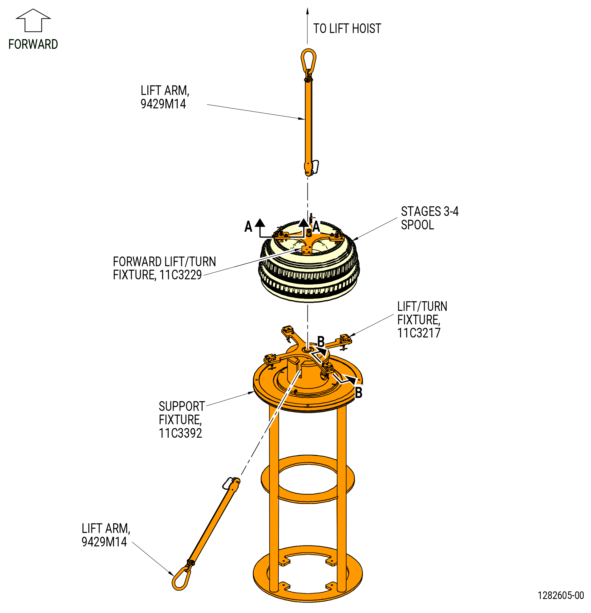
| (7) | Turn the stages 3-4 spool upside down to put the forward end on the 11C3009 support fixture installed on the stand (item 4) of the 11C3073 build-up stand as follows. Refer to Figure 519. |
| (a) | Put the 11C3217 lift/turn fixture on the 11C3392 support fixture. Make sure that the clamp (item 3) is secured in the STORAGE position. If not, push up on the retaining pin (item 4) and turn the clamps (item 3) to the STORAGE position. |
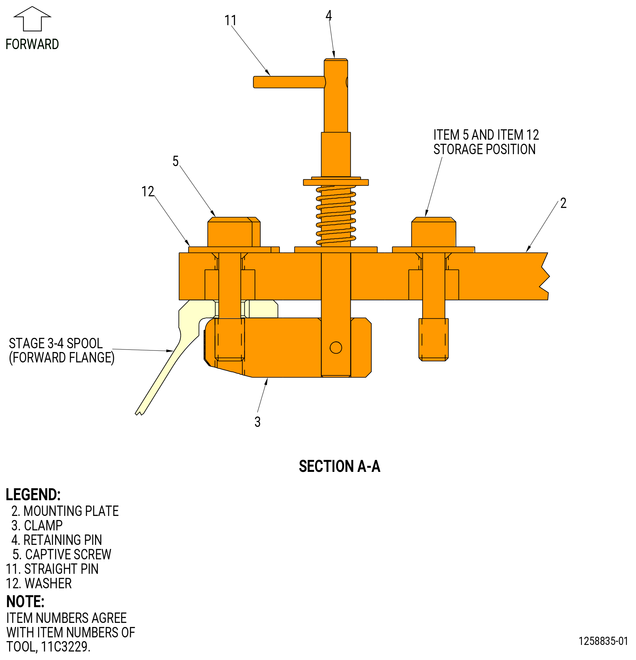
| (b) | Install the 11C3229 forward lift/turn fixture on the forward end of the stages 3-4 spool as follows: |
| 1 | Remove the screw (item 5) and the washer (item 12) from the clamp (item 3) in the STORAGE position. |
| 2 | Turn the retaining pin (item 4) with the straight pin (item 11) 180 degrees to align the STORAGE hole with the bolthole on the clamp (item 3). |
| 3 | Secure the clamp (item 3) in the STORAGE position to install the fixture on the stages 3-4 spool. |
| 4 | Put the 11C3229 forward lift/turn fixture on the forward flange of the stages 3-4 spool. |
| 5 | Remove the screw (item 5) and the washer (item 12) from the clamp (item 3) and turn the retaining pin (item 4) to put the clamp (item 3) below the aft side of the stages 3-4 spool forward flange. |
| 6 | Secure the three clamps (item 3) with the screw (item 5) and the washer (item 12) to the stages 3-4 spool forward flange. |
| (c) | Attach an 9429M14 lift arm to the 11C3229 forward lift/turn fixture. |
| WARNING: |
|
| (d) | Lift the stages 3-4 spool from the 11C3009 support fixture and lower the aft end of the stages 3-4 spool on the 11C3217 lift/turn fixture on the 11C3392 support fixture. |
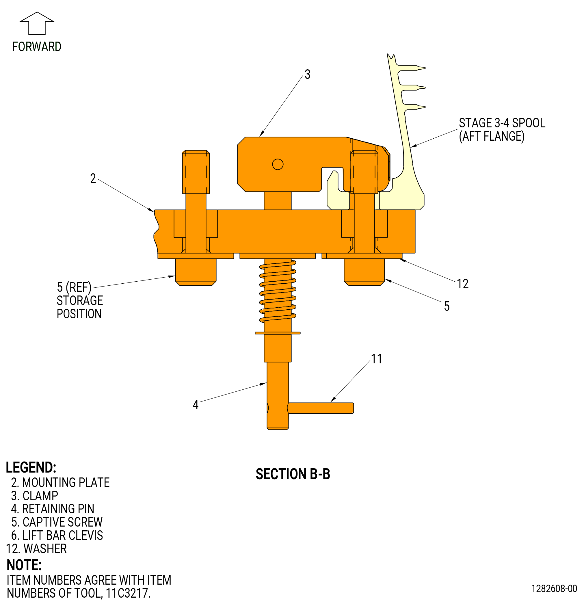
| (e) | Attach the 11C3217 lift/turn fixture to the aft end of the stages 3-4 spool as follows. Refer to Figure 518. |
| 1 | Remove the captive screws (item 5) from the clamps (item 3) in the STORAGE position on the mounting plate (item 2). |
| 2 | Push up on the retaining pin (item 4) and turn the clamp (item 3) to align with the captive screws (item 5). |
| 3 | Attach the four clamps (item 3) to the stages 3-4 spool aft flange with the eight captive screws (item 5). |
| (f) | Install a second 9429M14 lift arm to the 11C3217 lift/turn fixture. |
| (g) | Lift the stages 3-4 spool and use the two 9429M14 lift arm to turn the stages 3-4 spool upside down and install the forward end on the 11C3392 support fixture. |
| (h) | Remove the 9429M14 lift arm from the 11C3229 forward lift/turn fixture. |
| (i) | Remove the 11C3229 forward lift/turn fixture from the forward end of the stages 3-4 spool. |
| (j) | Lift the stages 3-4 spool from the 11C3392 support fixture and install the stages 3-4 spool on the 11C3009 support fixture and stand (item 4) of the 11C3073 build-up stand with the forward end down. Refer to Figure 519. |
| Subtask 72-31-00-040-035 |
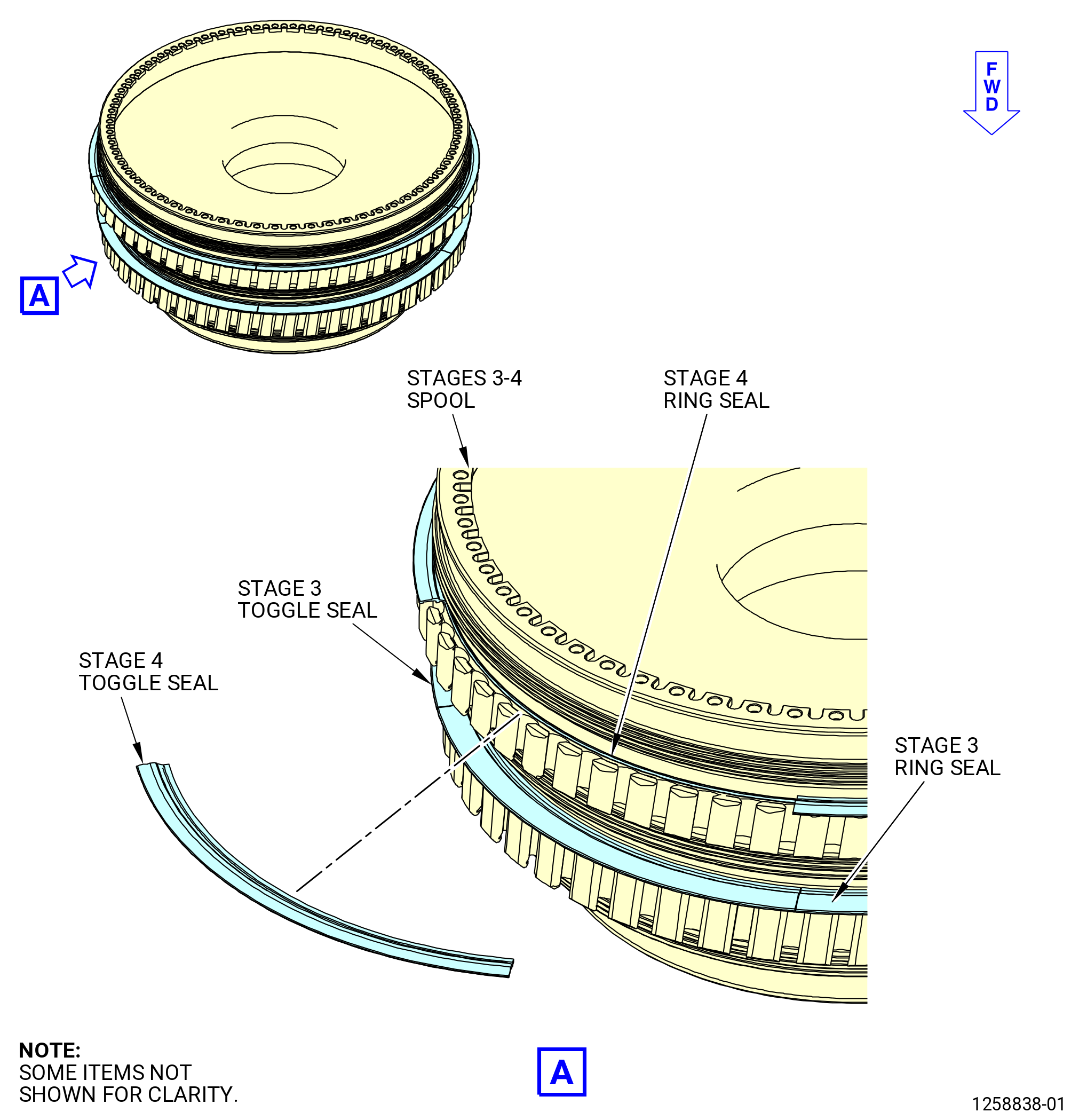
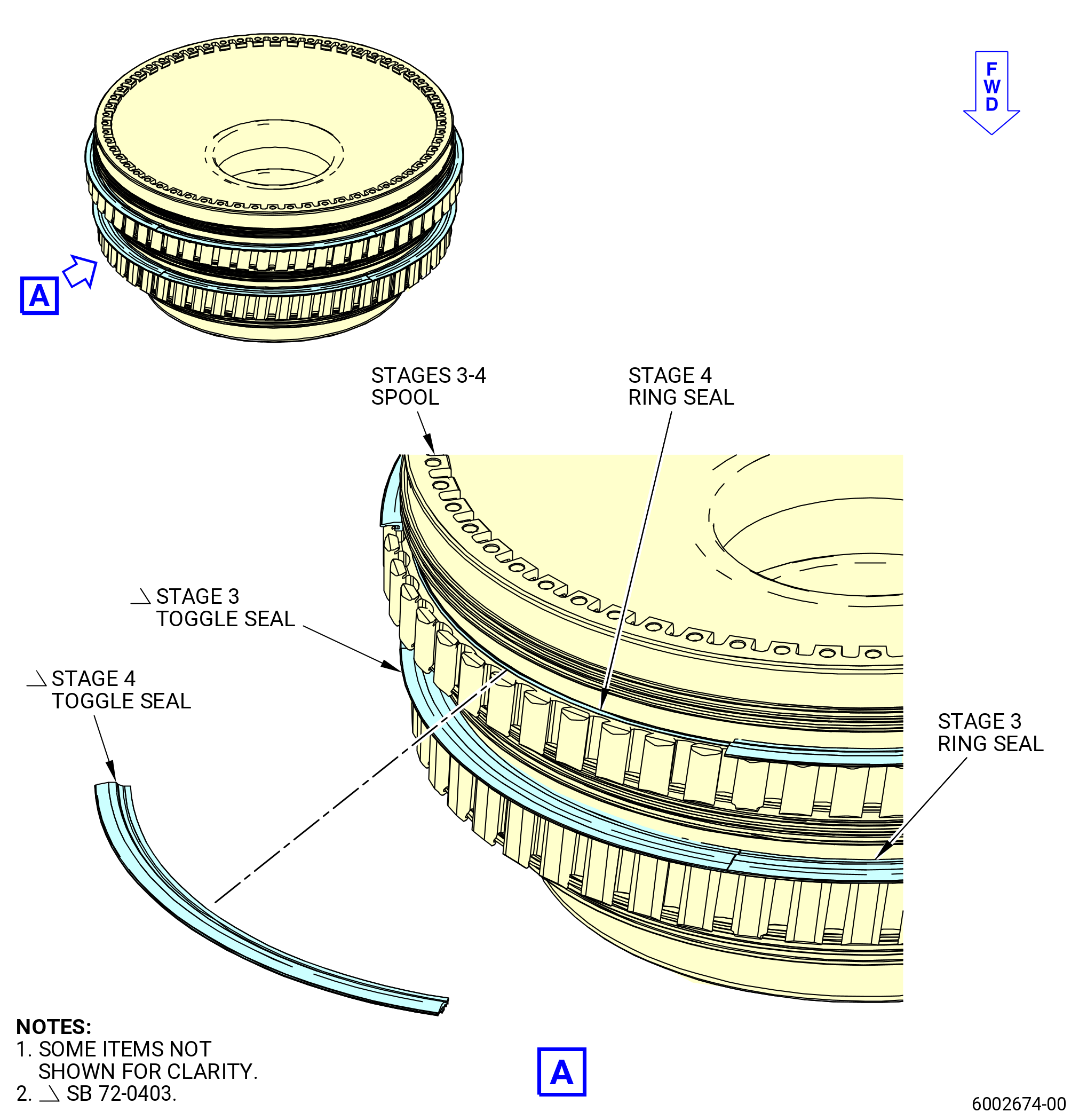
| (8) | Slide the toggle seals in their groove until the taps on the seals are aligned with the blade slots on the spool. Remove the toggle seals from the stage 3 and the stage 4 blade slots aft side. Refer to Figure 520. |
| (9) | Remove the stage 3 and the stage 4 ring seal from the stages 3-4 spool. |
| WARNING: |
|
| (10) | Lift the stages 3-4 spool from the 11C3009 support fixture and stand (item 4) of the 11C3073 build-up stand. Refer to Figure 519. |
| (11) | Turn the stages 3-4 spool forward end up. Refer to 72-31-00-040-034 (paragraph 3.F.(7)) and as follows. Refer to Figure 518. |
| (a) | Put the 11C3229 forward lift/turn fixture on the 11C3392 support fixture. |
| (b) | Lower the stages 3-4 spool on the 11C3229 forward lift/turn fixture. |
| (c) | Attach the 11C3299 forward lift/turn fixture to the stages 3-4 spool forward end. |
| (d) | Attach the 9429M14 lift arm to the 11C3299 forward lift/turn fixture. |
| (e) | Lift the stages 3-4 spool and use the two lift arms to turn the stages 3-4 spool to the aft end down. |
| (f) | Remove the 9429M14 lift arm and the 11C3217 lift/turn fixture from the aft end of the stages 3-4 spool. |
| (12) | Lower the stages 3-4 spool to the 11C3186 HPC rotor stand. Refer to Figure 510. |
| (13) | Remove the 9429M14 lift arm and the 11C3299 forward lift/turn fixture from the stages 3-4 spool. |
|
|
| Subtask 72-31-00-040-005 |
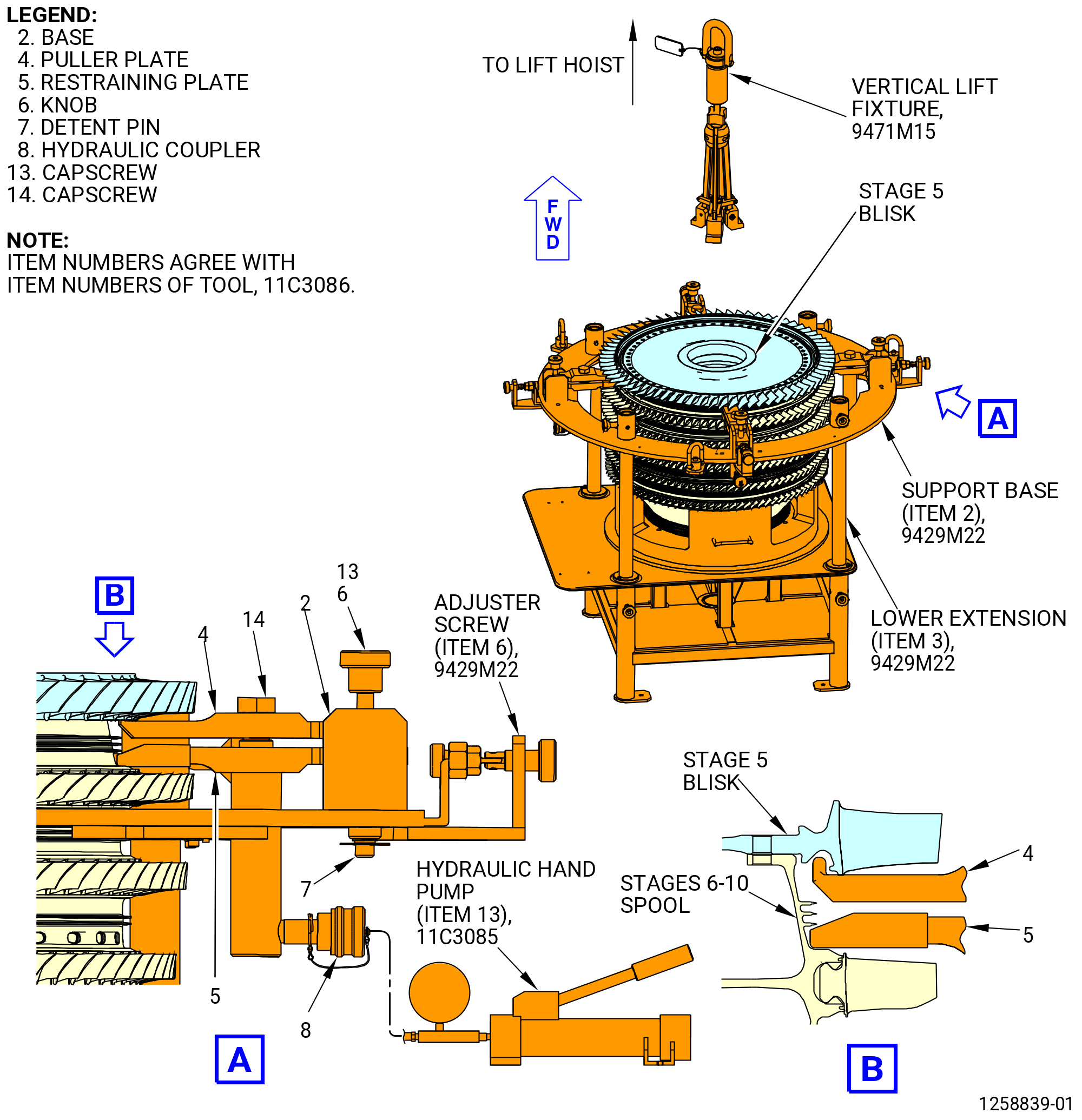
| I. | Remove the stage 5 blisk (01-490) (SIN 056A5) or (02-490) (SIN 056A5) from the HPC rotor assembly as follows: |
| (1) | Install the four fixture separators of the 11C3086 hydraulic puller on the support base (item 2) on the lower extension (item 3) of the 9429M22 support fixture as follows. Refer to Figure 521. |
| (a) | Before the stage 5 blisk is removed, install the posts (item 16) on the bushing of the support base and safety it with the ball-lock pin (item 5). Refer to Figure 512. |
| (b) | Install the subassembly of the arm (item 15) and make sure that the knurled screw (item 19) are fully retracted, then leave a gap of half inch between the bottom of the cushion (item 18) and the surface of the blisk. Tighten the capscrews (item 21) to 10 lb ft (13.55 Nm). |
| (c) | Lower the cushion up to touch the top surface of the stage 5 blisk with the knurled screws (item 19). |
| (d) | Turn the knob (item 6) of the 11C3086 hydraulic puller to move the puller plate (item 4) and the restraining plate (item 5) together. |
| (e) | Install the bases (item 2) of the 11C3086 hydraulic puller on the support base (item 2) on the lower extension (item 3) of the 9429M22 support fixture at the four locations. |
| CAUTION: |
|
| (f) | Attach the base with the detent pin (item 7) of the 11C3086 hydraulic puller. Make sure that you do not touch the stages 6-10 spool knife edges and the stage 5 blisk blades. |
| (g) | Turn the adjuster screw (item 6) on the lower extension (item 2) of the 9429M22 support fixture into the slot on the base (item 2) of the 11C3086 hydraulic puller. |
| (h) | Slide the puller plates (item 4) and the restraining plates (item 5) between the stages 6-10 spool and the stage 5 blisk. Make sure that you do not touch the stages 6-10 spool and the blades on the stage 5 blisk. |
| (i) | Turn the adjuster screw (item 6) on the lower extension of the 9429M22 support fixture to move the puller plates (item 4) of the 11C3086 hydraulic puller and the restraining plates (item 5) in or out. |
| (j) | Make sure that the distance between the puller plates (item 4) and restraining plates (item 5) are equal at the four locations. If necessary, adjust the distance. |
| (2) | Connect the hydraulic hand pump (item 13) of the 11C3085 clamp fixture to the hydraulic coupler (item 8) of the 11C3086 hydraulic puller. |
| Subtask 72-31-00-040-087 |
| (3) | Optional Procedure. Cooling or heating assistance. There are two alternative optional procedures available to help with the stage 5 blisk disassembly. One of them is heating the stage 5 blisk web, the other is cooling the stage 6-10 spool web. It is not recommended to use both at the same time. |
| Subtask 72-31-00-040-088 |
| WARNING: |
|
| CAUTION: |
|
| CAUTION: |
|
| (a) | Alternative Procedure Available. Use a propane torch or heat gun to increase the temperature of the stage 5 blisk to a maximum of 300°F (148°C). Heat the web area to prevent any damage to the airfoils. Make sure that you continually move the propane torch or heat gun around the stage 5 web and do not create any localized hot spots. |
| Subtask 72-31-00-040-089 |
| WARNING: |
|
| WARNING: |
|
| (a).A. | Alternative Procedure. Chill stage 6 disk of stage 6-10 spool with liquid nitrogen to approximately -13°F (-25°C). Measure temperature at the stage 5-6 spacer arm in four equally-spaced locations. |
| Subtask 72-31-00-040-090 |
| WARNING: |
|
| CAUTION: |
|
| CAUTION: |
|
| (4) | Apply hydraulic pressure to the hydraulic cylinders until the stage 5 blisk disengages from the stages 6-10 spool. |
| (5) | Disconnect the hydraulic hand pump (item 13) of the 11C3085 clamp fixture from the hydraulic coupler (item 8) of the 11C3086 hydraulic puller. |
| (6) | Install the 9471M15 vertical lift fixture on the stage 5 blisk. Refer to Figure 513, Figure 521, and do as follows: |
| (a) | Move the 9471M15 vertical lift fixture from the hoist ring (item 12) in the vertical position. |
| (b) | Attach a three-legged sling to the hoist ring (item 12). |
| (c) | Turn the hand knob (item 3) and hand knurled guide (item 7) to let the three arms (item 6) move to the inward position. |
| (d) | Put the 9471M15 vertical lift fixture in the bore of the stage 5 blisk. |
| (e) | Put the arms (item 6) on the bore diameter of the stage 5 blisk on the aft side. Make sure that the arms (item 6) engage correctly. |
| (f) | Tighten the hand knob (item 3) and hand knurled guide (item 7) to attach the arms (item 6). |
| WARNING: |
|
| (7) | Lift the stage 5 blisk and put it on the 11C3186 HPC rotor stand. Refer to Figure 510. |
| (8) | Remove the 9471M15 vertical lift fixture from the stage 5 blisk. |
| (a) | Move the 9471M15 vertical lift fixture from the hoist ring (item 12) in the vertical position. |
| (9) | Remove the 11C3086 hydraulic puller from the support base (item 2) on the lower extension (item 3) of the 9429M22 support fixture. |
| (10) | Remove the subassembly of the arm (item 15) and post (item 16). Refer to Figure 512. |
| (11) | Remove the support base (item 2) on the lower extension (item 3) of the 9429M22 support fixture from the 9429M21 vertical build stand. Refer to Figure 512. |
| (12) | Remove the 9429M22 support fixture from the 9429M21 vertical build stand as follows: |
| (a) | Attach the 9429M19 lift fixture to the hoist rings (item 8) of the 9429M22 support fixture. |
| (b) | Remove the ball-lock pins (item 5) that attach the 9429M22 support fixture to the 9429M21 vertical build stand. |
| (c) | Carefully lift the 9429M22 support fixture from the stand. |
| (13) | Install the 11C3419 blades protector set on the stage 5 blisk. |
| Subtask 72-31-00-040-009 |
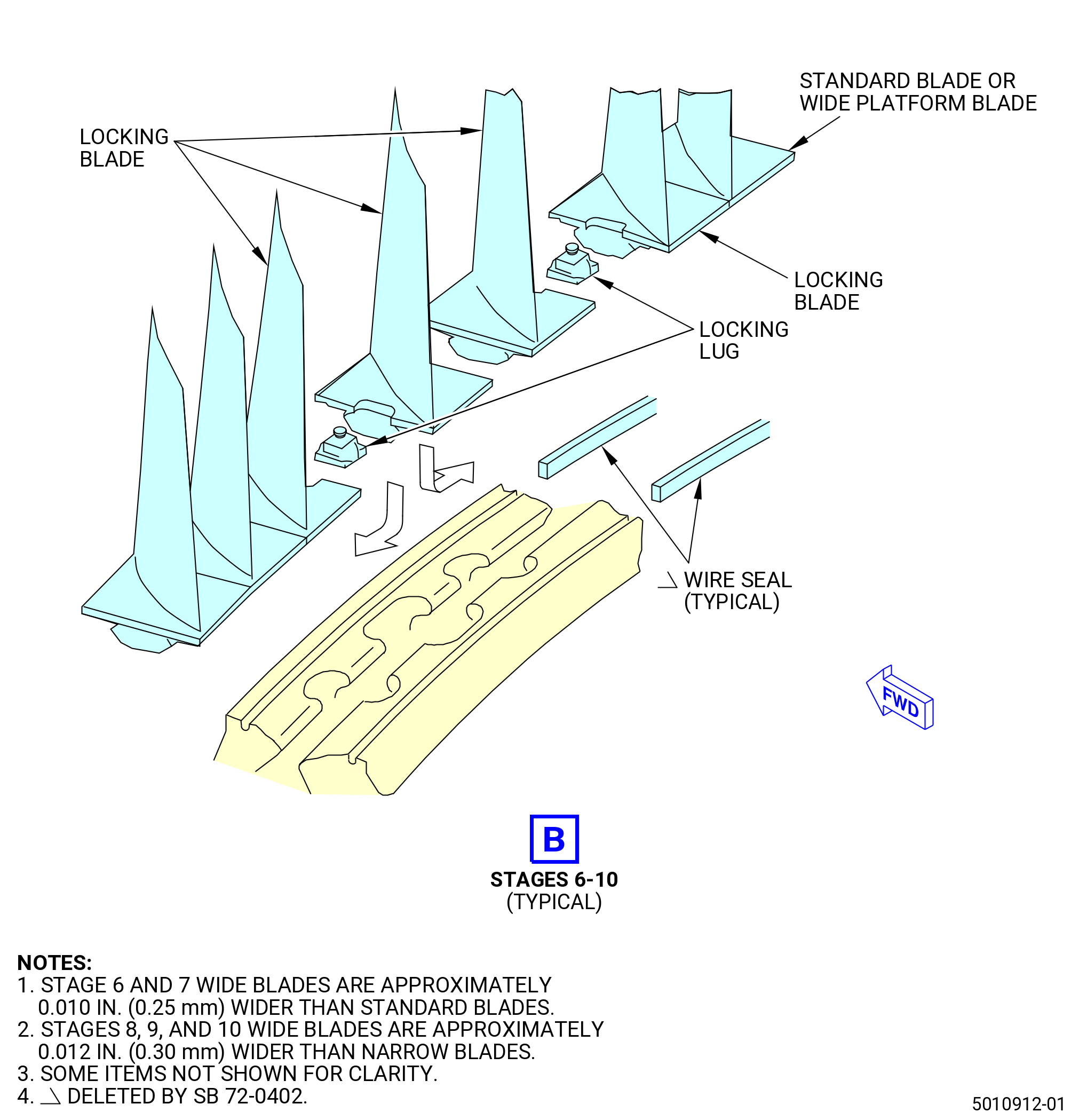
| J. | Remove the stage 6-10 blades from the stage 6-10 spool as follows. Refer to Figure 522. |
| (1) | Use the C05-003 pen to put a mark on the stage 6-10 blades to identify the blades. Refer to TASK 70-16-02-350-017 (TEMPORARY MARKING). |
| Subtask 72-31-00-040-073 |
| (2) | Alternative Procedure Available. Use a standard hex wrench to remove the locking lugs (01-010) (SIN 050AJ) or (01-010A) (SIN 050AJ), or (02-010) (SIN 050AJ), (01-100) (SIN 050AH) or (01-0100A) (SIN 050AH), or (02-100) (SIN 050AH), (01-190) (SIN 050AG) or (01-0190A) (SIN 050AG), or (02-190) (SIN 050AG), (01-280) (SIN 050B2) or (01-0280A) (SIN 050B2), or (02-280) (SIN 050B2), and (01-370) (SIN 050B0) or (02-370) (SIN 050B0) in each stage. Discard the locking lugs (01-010) (SIN 050AJ) or (01-010A) (SIN 050AJ), or (02-010) (SIN 050AJ), (01-100) (SIN 050AH) or (01-0100A) (SIN 050AH), or (02-100) (SIN 050AH). |
| Subtask 72-31-00-040-074 |
| (2).A. | Alternative Procedure. If the locking lugs cannot be removed with the standard hexagonal wrench, refer to TASK 72-31-00-800-801 (72-31-00, SPECIAL PROCEDURE 001). |
| (a) | Deleted. |
| Subtask 72-31-00-040-075 |
| WARNING: |
|
| (3) | If necessary, apply C02-019 engine oil or C02-023 engine oil on the locking lugs to help with their removal. |
| (4) | Move the blades around the spool as necessary to remove the locking blades. |
| (5) | Remove the standard and wide platform blades from the stages 6-10 spool. |
| (6) | If necessary, remove the balance weights. |
| Subtask 72-31-00-040-079 |
| * * * FOR 1B/P/G03.1B/P/G04.1B/P1/G01 |
| (7) | Remove and discard the wire seals from the forward and aft grooves of the 6-10 stage spools as follows: |
|
| Subtask 72-31-00-040-080 |
| * * * FOR ALL PIP 2 |
| * * * PRE SB 72-0402( HPT Rotor Assembly with Wire Seals ) |
| (8) | Remove and discard the wire seals from the forward and aft grooves of the 6-10 stage spools as follows: |
| NOTE: |
|
|
| * * * END PRE SB 72-0402 |
| Subtask 72-31-00-040-006 |
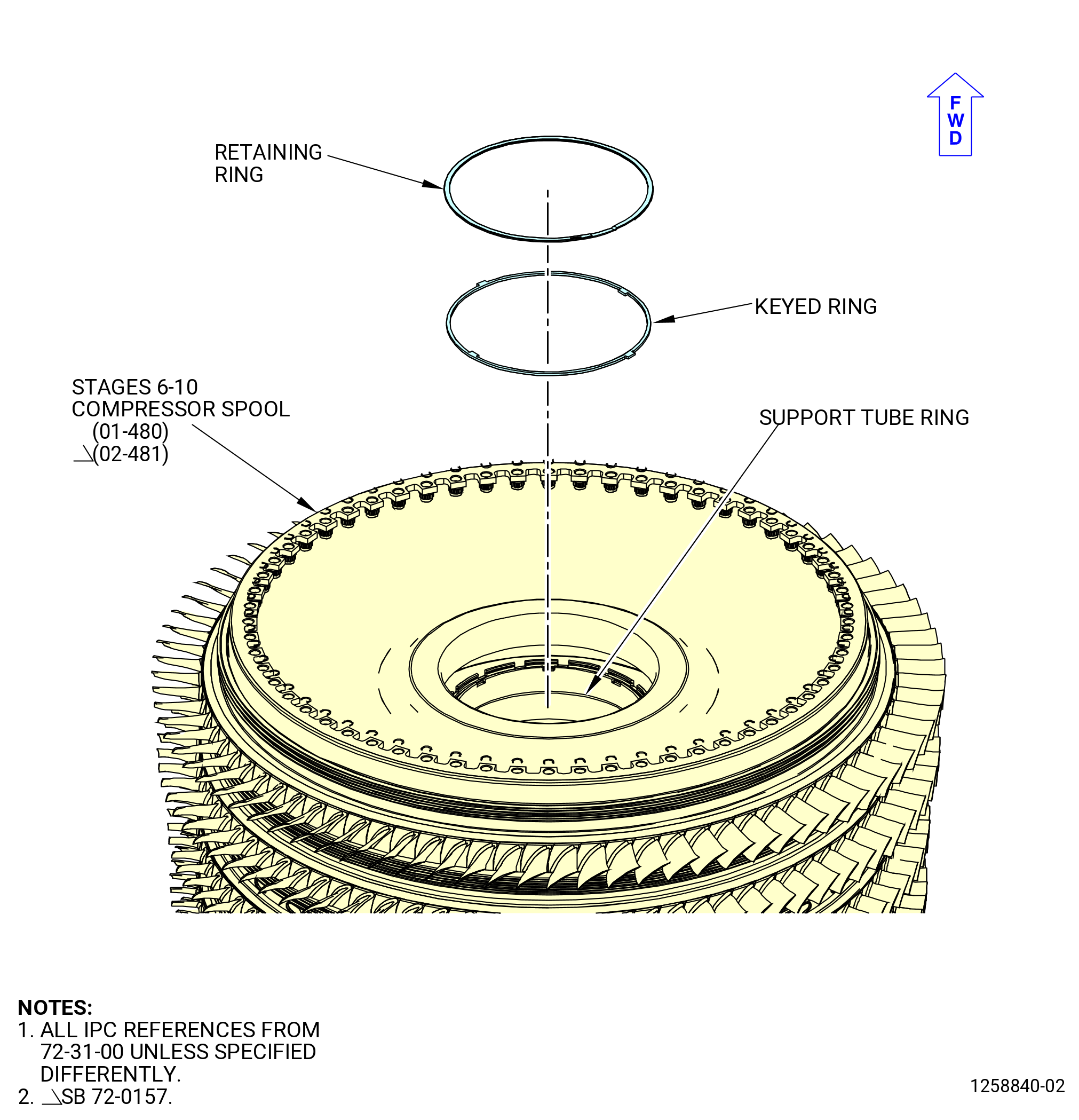
| K. | Disassemble the stages 6-10 compressor spool (01-480) (SIN 050AR) or (02-481) (SIN 050AR) as follows: |
| (1) | Remove the retaining ring and the keyed ring from the support tube end. Refer to Figure 523. |
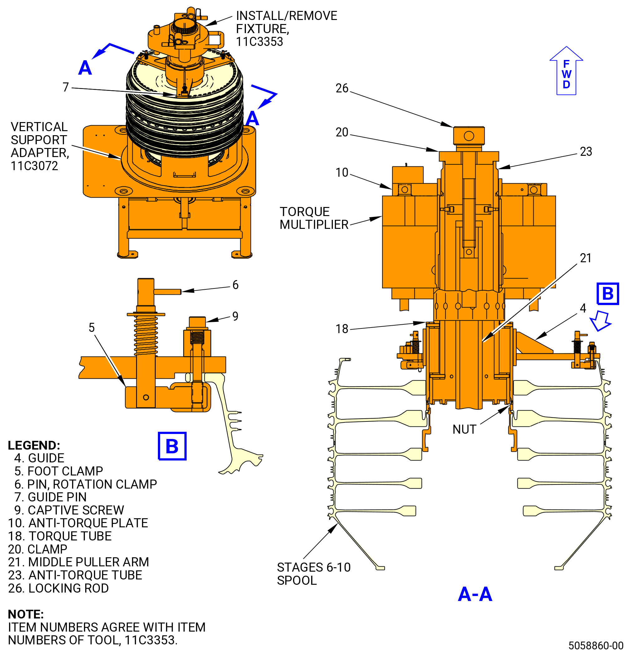
| (2) | Install the 11C3353 install/remove fixture and torque multiplier on the forward end of the stages 6-10 spool as follows. Refer to Figure 524. |
| (a) | Put the middle puller arm (item 21) through the stage 6-10 spool and engage the threads with the hydraulic cylinder of the 11C3085 clamp fixture. |
| (b) | Turn the three rotation clamp pins (item 6) to put the foot clamp (item 5) in an inward or storage position when you install the guide (item 4). |
| WARNING: |
|
| (c) | Lift the 11C3353 install/remove fixture and install it on the stages 6-10 spool. Adjust the fixture on the spool with the guide pins (item 7). |
| (d) | Turn the three rotation clamp pins (item 6) to put the foot clamp (item 5) below the stages 6-10 spool forward flange. |
| (e) | Secure the foot clamp (item 5) with the captive screw (item 9). Tighten only enough to prevent movement. Do not torque the captive screw (item 9). |
| (f) | Attach an overhead hoist to the pin inside the anti-torque tube (item 23) and lift the tube and the torque tube (item 18). |
| (g) | Install the anti-torque tube (item 23) and the torque tube (item 18) in the guide (item 4) and remove the hoist. |
| (h) | Turn the anti-torque tube (item 23) and the torque tube (item 18) to engage the castellations on the anti-torque tube (item 23) in the slots of the support tube ring. |
| (i) | Use an overhead hoist to lift and install the torque multiplier on the torque tube (item 18) of the 11C3353 install/remove fixture. Put the torque multiplier on the torque tube (item 18) to turn in the CCW direction and remove the nut from the support tube ring. |
| (j) | Put the torque multiplier on the torque tube (item 18) to turn in the CCW direction and remove the nut from the support tube ring. |
| (k) | Install the anti-torque plate (item 10) on the torque multiplier and in the external spline of the anti-torque tube (item 23) of the 11C3353 install/remove fixture. |
| (l) | Attach the anti-torque plate (item 10) to the torque multiplier with the anti-torque plate retaining pins. |
| (m) | Turn the anti-torque tube (item 23) of the 11C3353 install/remove fixture and the torque tube (item 18) by hand to make sure that the torque tube (item 18) is engaged correctly in the nut on the support tube ring. |
| (n) | Put the clamp (item 20) on the top of the anti-torque tube (item 23) and install the locking rod (item 26) through them. Engage the locking rod (item 26) thread with the middle puller arm (item 21). Make sure that these items are centered. Hand-tighten the locking rod. |
| (3) | Use the torque multiplier to loosen the nut on the support tube ring. If necessary, use an anti-torque bar in the anti-torque plate (item 10) of the 11C3353 install/remove fixture. Keep the nut installed on the support tube ring with two or more threads engaged. |
| (4) | Remove the anti-torque plate (item 10) from the torque multiplier. |
| (5) | Use an overhead hoist to lift and remove the torque multiplier from the torque tube (item 18) of the 11C3353 install/remove fixture. |
| (6) | Remove the 11C3353 install/remove fixture from the stages 6-10 spool on the HPC rotor assembly. |
| (7) | Remove the nut from the support tube ring. |
| Subtask 72-31-00-040-007 |
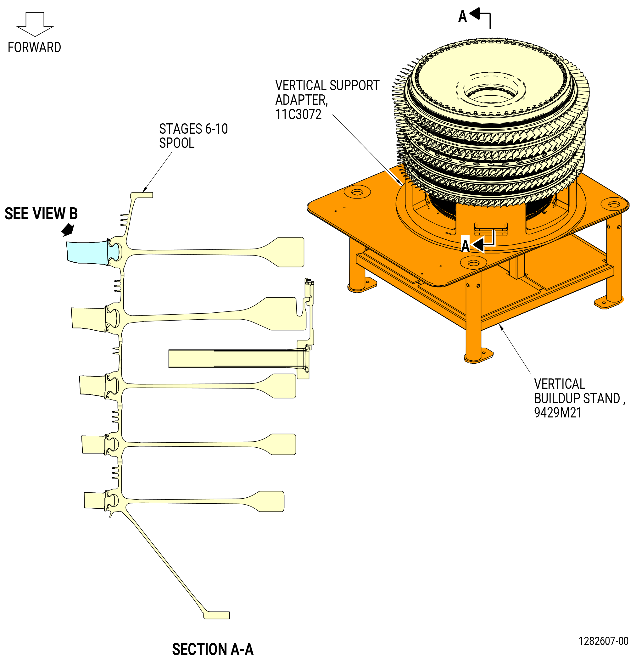
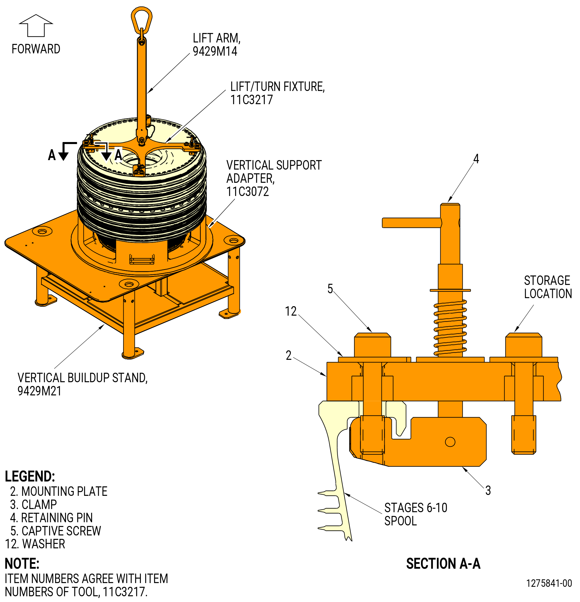
| (8) | Remove the stages 6-10 spool from the 11C3072 vertical support adapter installed on the 9429M21 vertical buildup stand as follows. Refer to Figure 525. |
| (a) | Install the 11C3217 lift/turn fixture on the stages 6-10 spool forward flange as follows: |
| 1 | Make sure that the clamps (item 3) are attached to the four captive screws (item 5) and washers (item 12) in the STORAGE position. If not, push down on the retaining pin (item 4) and turn the clamps (item 3) to the STORAGE position. |
| 2 | Attach a 9429M14 lift arm to the 11C3217 lift/turn fixture |
| WARNING: |
|
| 3 | Lift the 11C3217 lift/turn fixture and align the eight captive screws (item 5) with the flange boltholes of the stages 6-10 spool. Install the fixture on the stage 6-10 spool. |
| 4 | Disengage the captive screws (item 5) at the STORAGE position from the mounting plate (item 2). |
| 5 | Push down on the retaining pin (item 4) and turn the clamps (item 3) to align them with the eight captive screws (item 5) holes. |
| 6 | Attach the clamps (item 3) to the stages 6-10 spool flange with the eight captive screws (item 5) and the washers (item 12). |
| Subtask 72-31-00-040-008 |
| (9) | If necessary, install the 11C3074 dummy bolt tool kit on the CDP rotating seal (01-460) (SIN 050NC) or (02-460) (SIN 050NC). Refer to Subtask 72-31-00-040-001 (paragraph 3.A.(2)). |
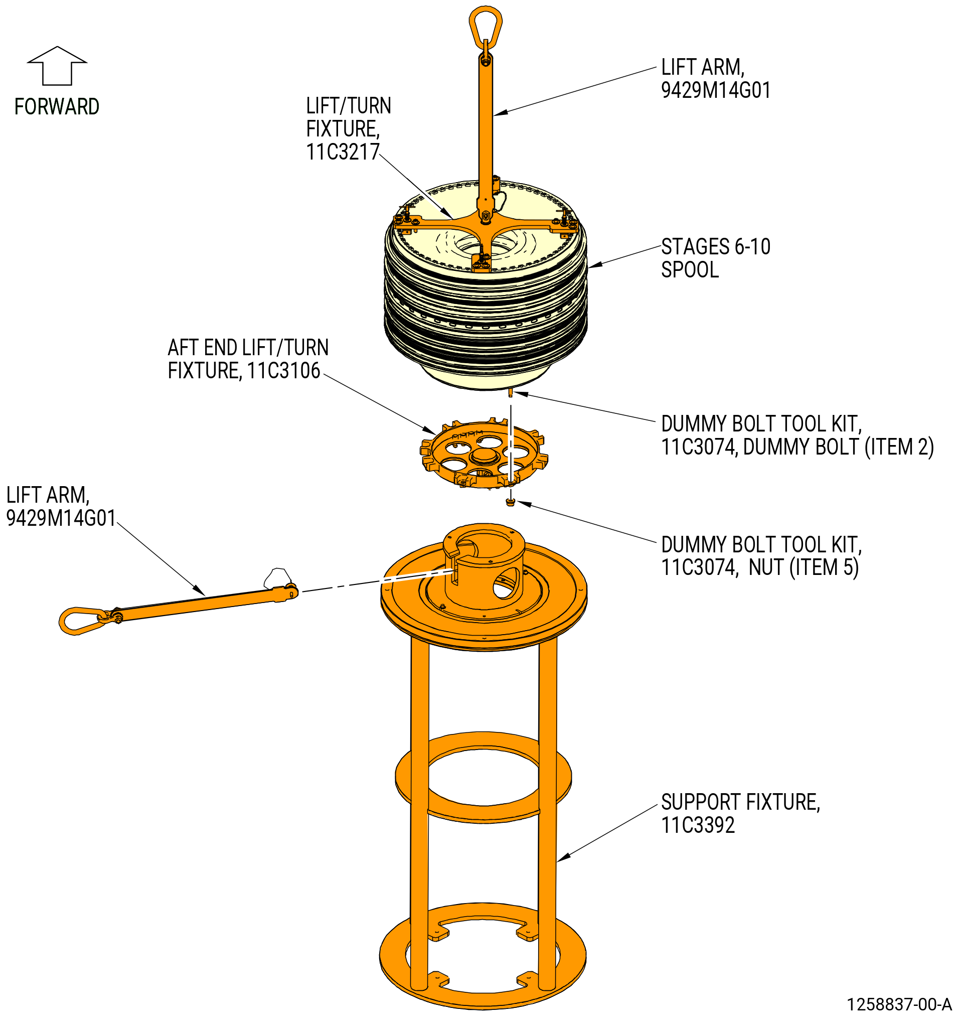
| (10) | Put the 11C3106 aft end lift/turn fixture on the 11C3392 support fixture. Refer to Figure 526. |
| WARNING: |
|
| (11) | Lift the stages 6-10 spool from the 11C3072 vertical support adapter. |
| (12) | Lower the stages 6-10 spool aft end on the 11C3106 aft end lift/turn fixture. Attach the fixture to the spool as follows. Refer to Figure 526. |
| (a) | Lower the stages 6-10 spool and align the dummy bolts (item 2) of the 11C3074 dummy bolt tool kit with the boltholes on the 11C3106 aft end lift/turn fixture. |
| (b) | Attach the 11C3106 aft end lift/turn fixture with the nuts (item 5) of the 11C3074 dummy bolt tool kit. |
| (13) | Attach a 9429M14 lift arm to the 11C3106 aft end lift/turn fixture. |
| (14) | Attach the 9429M14 lift arm to an overhead hoist. |
| (15) | Carefully lift the stages 6-10 spool from the 11C3392 support fixture with the first hoist. Turn the stages 6-10 spool with the two overhead hoists to put the forward end down. |
| (16) | Install the stages 6-10 spool forward end on the 11C3392 support fixture. |
| (17) | Remove the 9429M14 lift arm and the 11C3217 lift/turn fixture from the forward end of the stages 6-10 spool. |
| (18) | Lift the stages 6-10 spool from the 11C3392 support fixture and install on the stand (item 4) of the 11C3073 build-up stand. Refer to Figure 527. |
| (19) | Remove the 9429M14 lift arm and the 11C3106 aft end lift/turn fixture from the aft end of the stages 6-10 spool. |
| (20) | Remove the 11C3074 dummy bolt tool kit from the aft end of the stages 6-10 spool, but keep two or three dummy bolts and nuts, equally spaced, to help with the removal of the CDP rotating seal. |
| Subtask 72-31-00-040-077 |
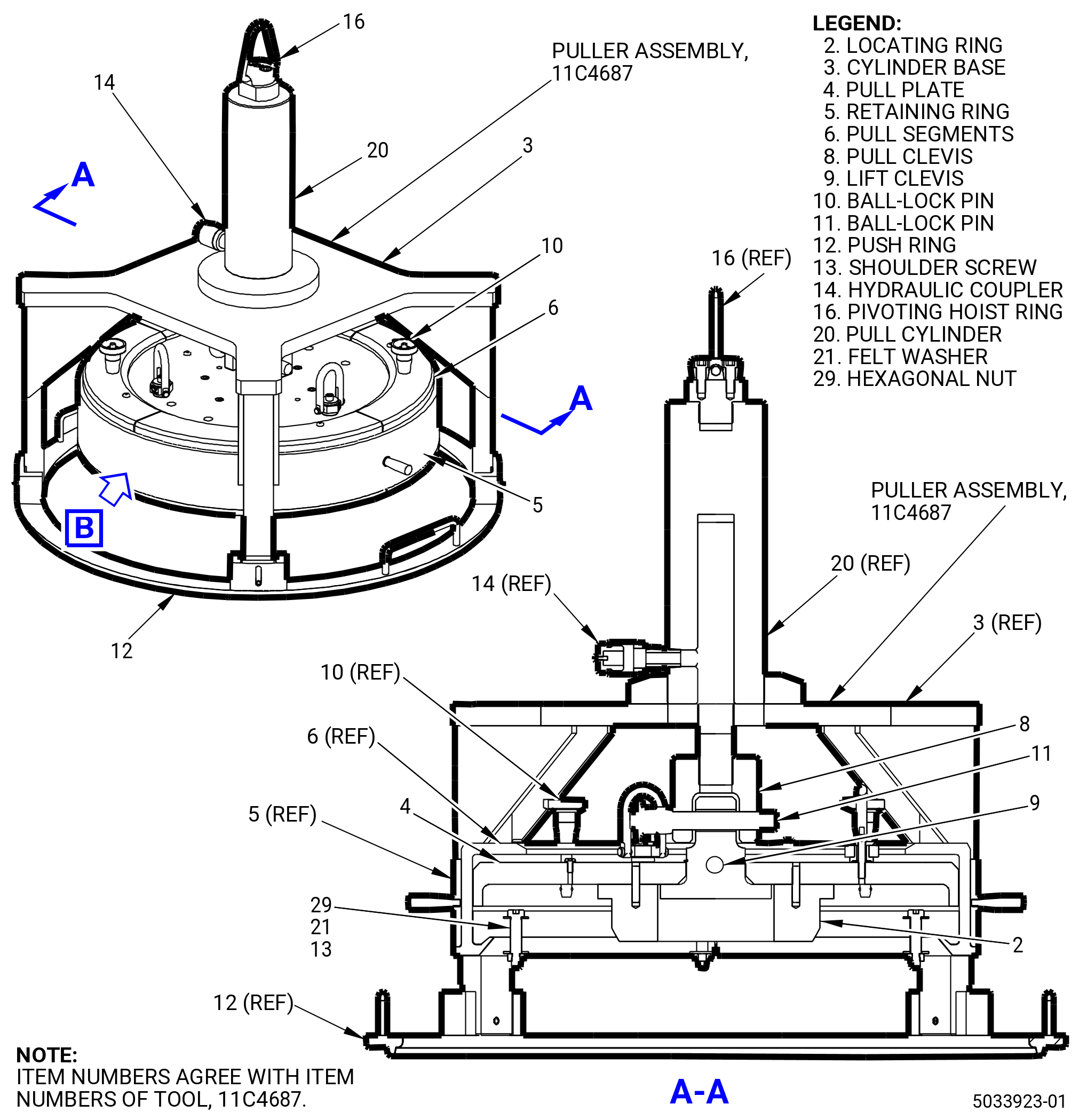
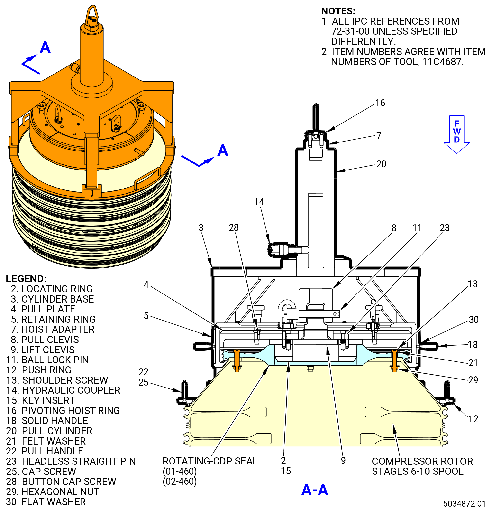
| L. | Alternative Procedure Available. Remove the CDP seal (01-460) (SIN 050NC) or (02-460) (SIN 050NC) from the stages 6-10 compressor spool (stage 6-10 spool). Refer to Figure 533 and do as follows: |
| (1) | Remove all CDP seal bolts or the 11C3074 dummy bolt tool kit from the CDP seal flange. |
| CAUTION: |
|
| (2) | Remove the four shoulder screws (item 13), hexagonal nuts (item 29), and eight felt washers (item 21) of the 11C4687 hydraulic puller from their storage location on the pull plate (item 4). |
| (3) | Install the four shoulder screws (item 13), hexagonal nuts (item 29), and felt washers (item 21) through the CDP seal, approximately equally spaced. One felt washer (item 21) must be installed on either side of the flange. |
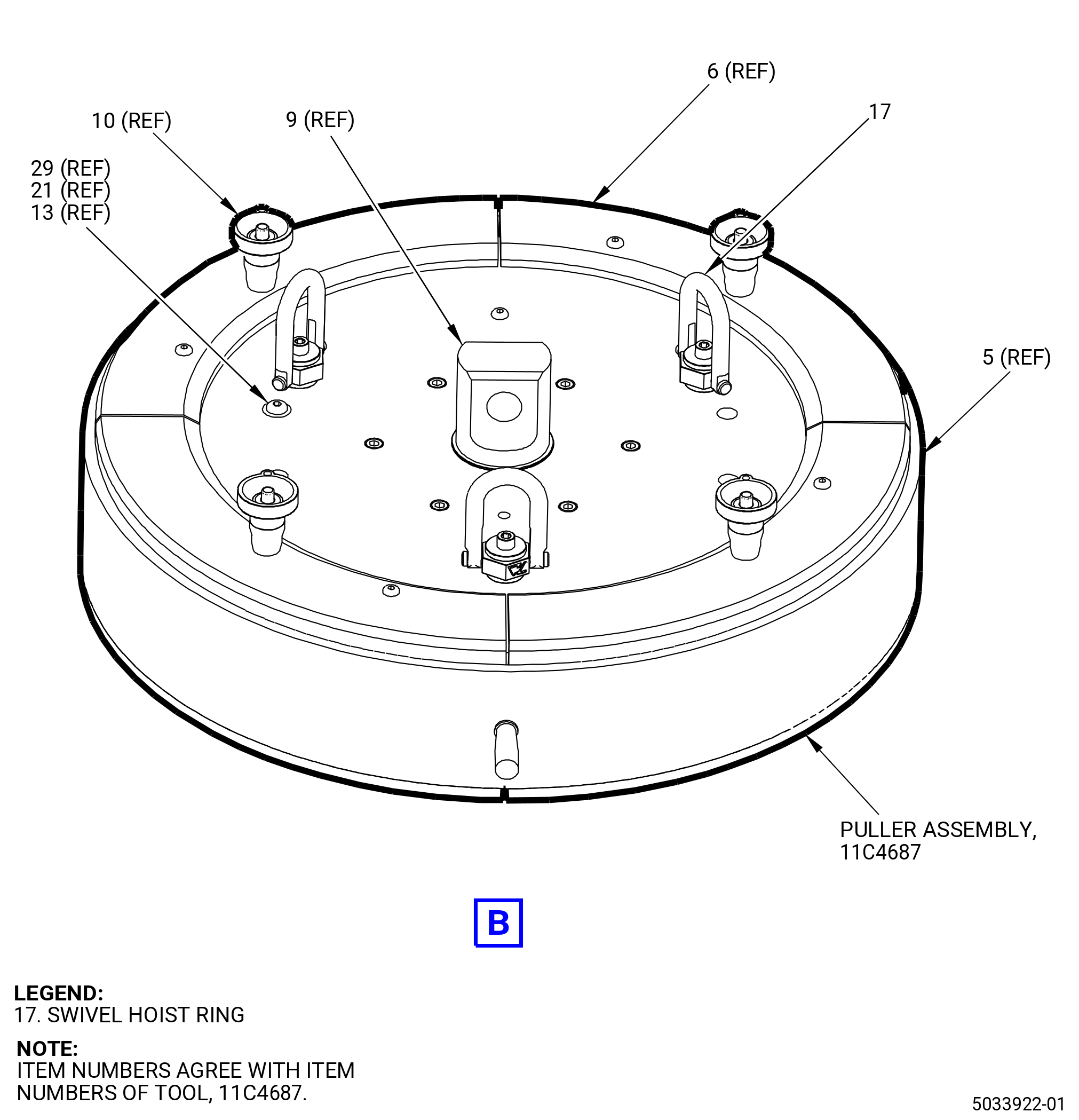
| (4) | Attach an overhead hoist (minimum capacity 31.8 kg (70 lb)) to the three swivel hoist rings (item 17) on the pull plate (item 4). |
| WARNING: |
|
| (5) | Lift the pull plate (item 4) and lower it on the CDP seal so that the locating ring (item 2) is centered inside the bore of the seal. |
| (6) | Disengage the overhead hoist from the swivel hoist rings (item 17). |
| (7) | Install each of the four pull segments (item 6) by sliding them under the teeth of the CDP seal and up along the slope of the stages 6-10 spool until a ball-lock pin (item 10) can be installed through the holes in both the pull segments (item 6) and the pull plate (item 4). |
| (8) | Install the retaining ring (item 5) over the four pull segments (item 6). |
| (9) | Attach an overhead hoist (minimum capacity 113.4 kg (250 lb)) to the pivoting hoist ring (item 16). |
| WARNING: |
|
| (10) | Lift the support frame assembly on the stages 6-10 spool, turning the lift clevis (item 9) as necessary to align with the pull clevis (item 8). |
| (11) | Make sure that the push ring (item 12) is centered on and resting flat against the aft side of the spool, then remove the overhead hoist. |
| (12) | Install the ball-lock pin (item 11) through both clevises (item 8 and item 9). The cylinder (item 20) piston can be axially adjusted to line up the clevises (item 8 and item 9). |
| (13) | Attach a 700 bar (10,000 psi) Enerpac hydraulic pump to the hydraulic coupler (item 14). |
| WARNING: |
|
| CAUTION: |
|
| (14) | Operate the Enerpac hydraulic pump to free the CDP seal from the stages 6-10 spool. |
| (15) | Re-attach the overhead hoist to the pivoting hoist ring (item 16). |
| (16) | Remove the ball-lock pin (item 11) from the clevises (item 8 and item 9). |
| WARNING: |
|
| (17) | Lift the support frame assembly away from the rest of the tool. |
| (18) | Remove the retaining ring (item 5). |
| (19) | For each of the four pull segments (item 6), remove the ball-lock pin (item 10) that is attaching the segment in place, then slide it down, out, and away from the CDP seal. |
| (20) | Attach an overhead hoist (minimum capacity 31.8 kg (70 lb)) to the three swivel hoist rings (item 17) on the pull plate (item 4) and lift the plate off of the CDP seal. |
| (21) | Remove the hexagonal nuts (item 29) from the shoulder screws (item 13) and move the shoulder screws (item 13), washers (item 21), and hexagonal nuts (item 29) to the storage location on the pull plate (item 4). |
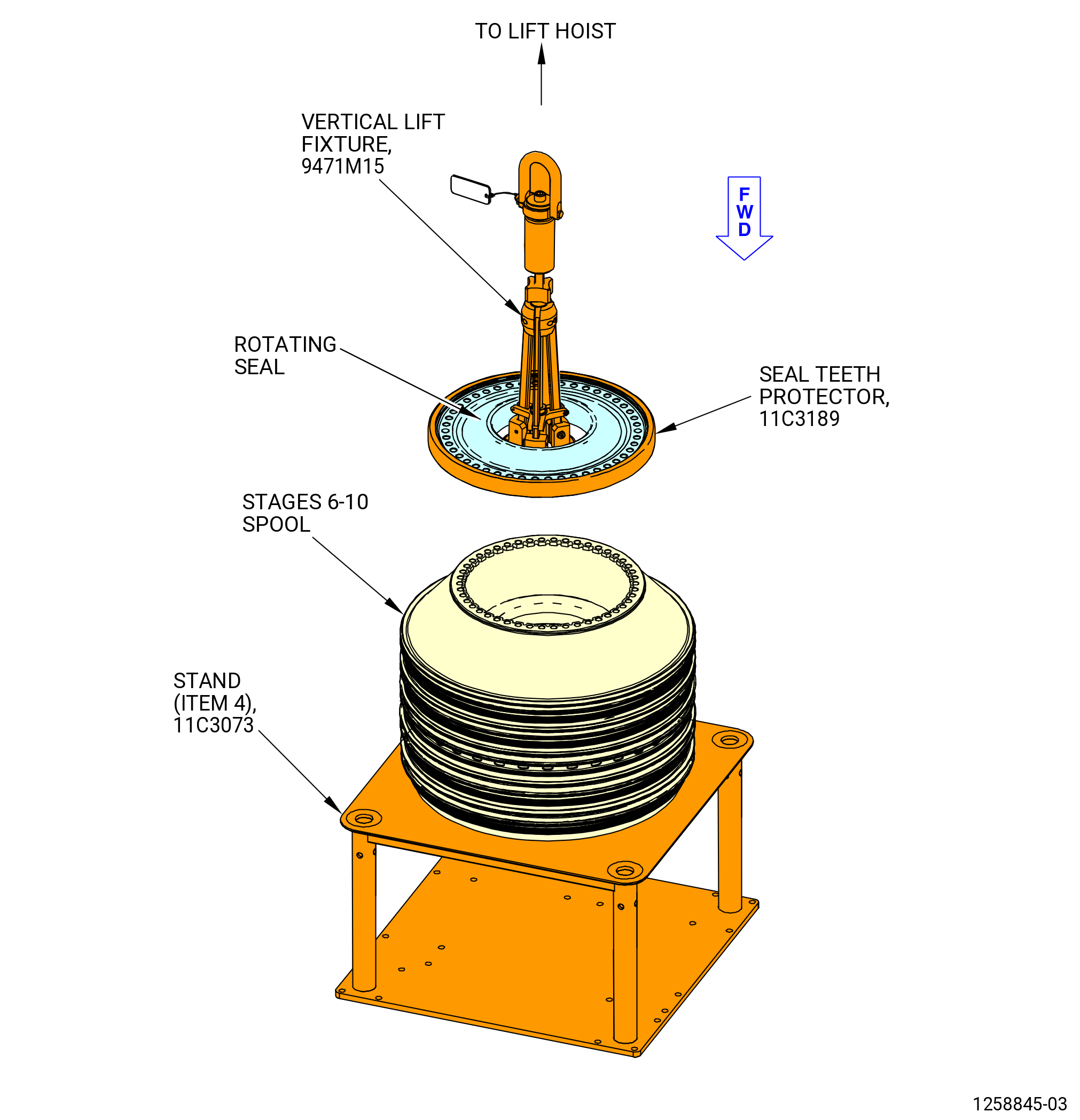
| (22) | Install the 11C3189 seal teeth protector on the CDP rotating seal. |
| (23) | Attach the 9471M15 vertical lift fixture to the CDP rotating seal. Refer to Figure 513, Figure 530, and do as follows: |
| (a) | Move the 9471M15 vertical lift fixture from the hoist ring (item 12) in the vertical position. |
| (b) | Attach a three-legged sling to the hoist ring (item 12). |
| (c) | Turn the hand knurled guide (item 7) and hand knob (item 3) to let the three arms (item 6) move to the inward position. |
| (d) | Put the 9471M15 vertical lift fixture in the bore of the CDP rotating seal. |
| (e) | Put the arms (item 6) on the bore diameter of the CDP rotating seal. Make sure that the arms (item 6) engage correctly. |
| (f) | Tighten the hand knurled guide (item 7) and hand knob (item 3) to attach the arms (item 6) in position. |
| WARNING: |
|
| (24) | Lift and put the CDP rotating seal and the 11C3189 seal teeth protector in a safe location. |
| (25) | Remove the 9471M15 vertical lift fixture from the CDP rotating seal. |
| Subtask 72-31-00-040-036 |
| L.A. | Deleted. |
| Subtask 72-31-00-040-078 |
| L.B. | Alternative Procedure. Remove the CDP rotating seal (01-460) (SIN 050NC) or (02-460) (SIN 050NC) from the stages 6-10 spool. Refer to Figure 528 and do as follows: |
| (1) | Remove all CDP seal bolts or the 11C3074 dummy bolt tool kit from the CDP seal flange. |
| WARNING: |
|
| CAUTION: |
|
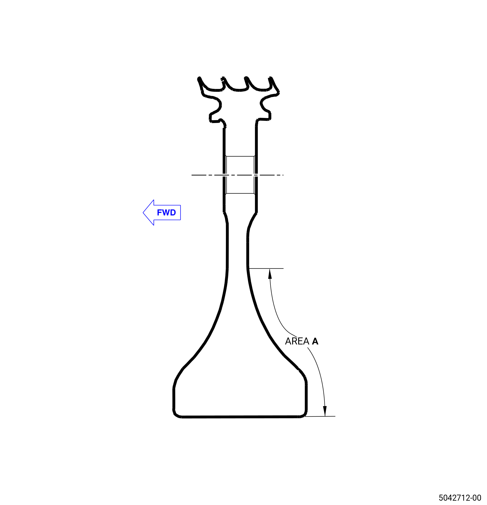
| (2) | Heat the area A of the CDP rotating seal aft bore face. Use a propane torch or heat gun in a circular motion and increase the temperature of the CDP seal until the temperature reaches to 104 to 122°F (40 to 50°C). |
| NOTE: |
|
| (3) | Check for the looseness of the CDP rotating seal. If necessary, continue increasing the temperature by 5-degree and repeat until the part becomes loose. |
| CAUTION: |
|
| (4) | Lift and put the CDP rotating seal in a safe location. |
| Subtask 72-31-00-040-037 |
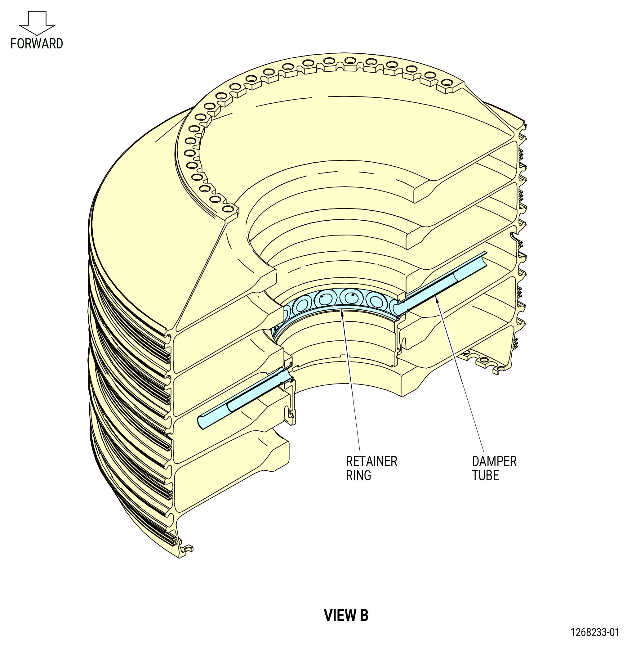
| M. | Remove the retainer ring from the stages 6-10 spool with hand tools. Refer to Figure 531. |
| Subtask 72-31-00-040-038 |
| N. | Remove the 18 damper tubes from the impeller tubes with hand tools. Refer to Figure 531. |
| Subtask 72-31-00-040-039 |
| O. | Remove the 18 impeller tubes from the stages 6-10 spool with hand tools. Refer to Figure 531. |
| Subtask 72-31-00-040-040 |
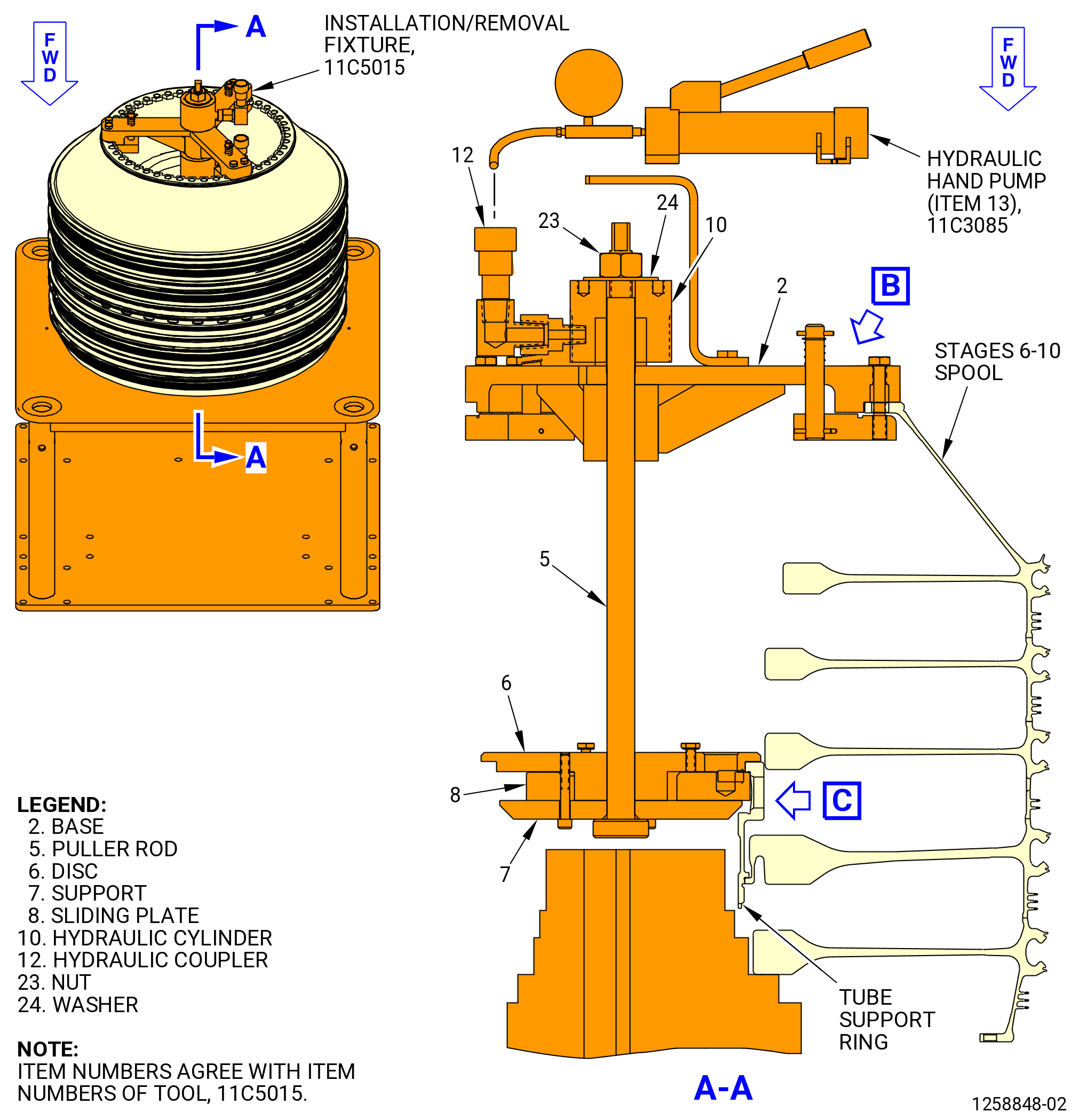
| P. | Remove the tube support ring (01-580) (SIN 050AM) or (02-580) (SIN 050AM) from the stages 6-10 spool. Refer to Figure 532 and do as follows: |
| (1) | Install the 11C5015 installation/removal fixture on the aft flange of the stages 6-10 spool as follows: |
| (a) | Install the support (item 7) and the disc (item 6) on the tube support ring as follows: |
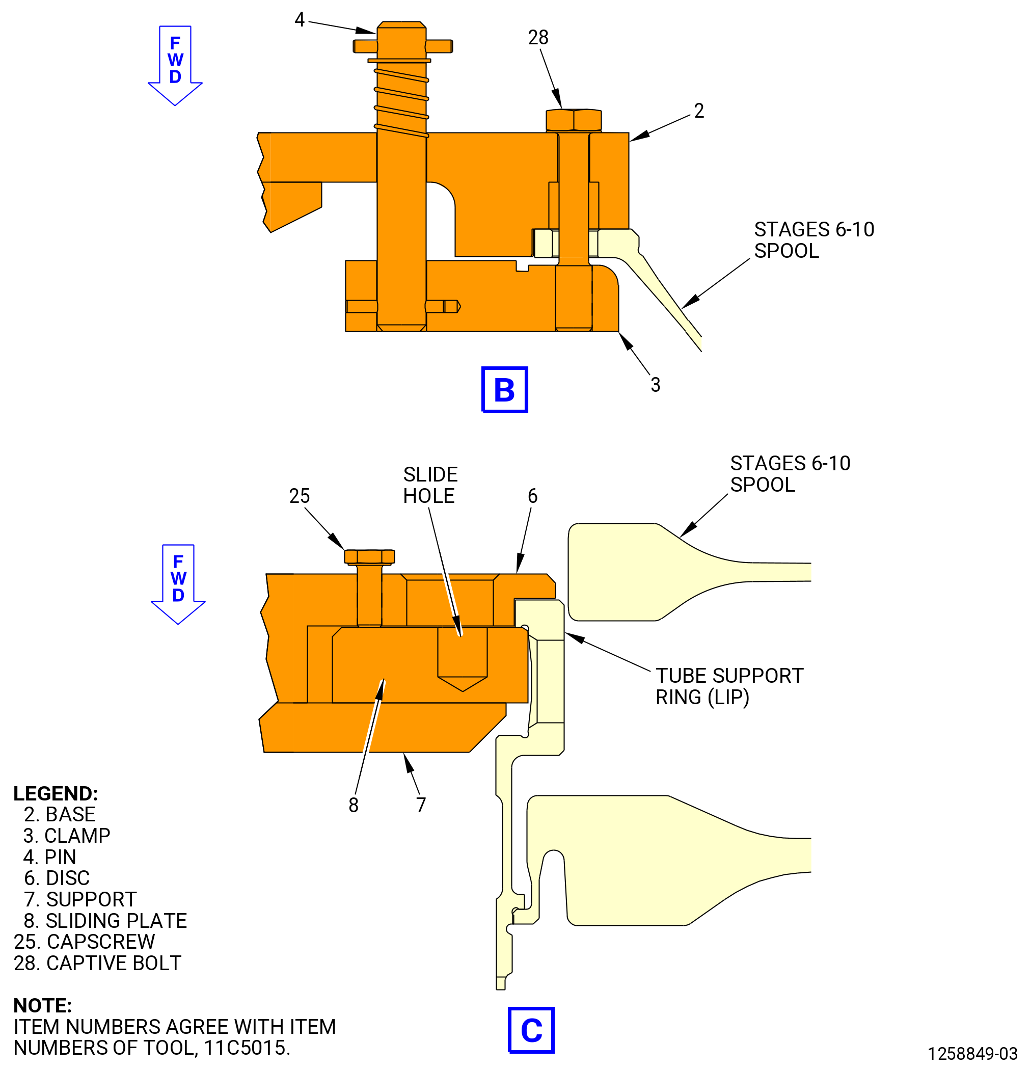
| 1 | Loosen the capscrew (item 25) and move the sliding plate (item 8) to the inward position. The 0.50 inch (12.7 mm) slide hole must be in the inward position in direction to the puller rod (item 5), to install the disc (item 6) on the tube support ring. Turn the capscrew (item 25) CW to attach the sliding plate (item 8). |
| NOTE: |
|
| 2 | Carefully lower the support (item 7) and disc (item 6) to the puller rod (item 5) into the stages 6-10 spool. Put the disc (item 6) on the tube support ring aft end. |
| 3 | Loosen the capscrew (item 25) and move the sliding plate (item 8) out below the lip of the tube support ring. You can use the 0.50 inch (12.7 mm) slide hole to move the sliding plate (item 8) below the lip of the tube support ring. |
| NOTE: |
|
| 4 | Turn the capscrew (item 25) CW to attach the sliding plate (item 8). |
| (b) | Turn the captive bolt (item 28) CCW to remove from the clamp (item 3). |
| (c) | Press down on the pin (item 4) and turn the clamp (item 3) 90 degrees from the base (item 2). Remove the guard (item 11) from the base (item 2). |
| (d) | Install the base (item 2) on the puller rod (item 5) and align the bolts (item 28) with the boltholes of the stages 6-10 spool aft flange. |
| (e) | Put the washer (item 24) and the hydraulic cylinder (item 10) on the puller rod (item 5). |
| (f) | Attach the nut (item 23) to the puller rod (item 5). Re-install the guard (item 11) on the base (item 2). |
| (g) | Push down on the pin (item 4) to turn the clamp (item 3) below the forward side of the stages 6-10 spool aft flange. |
| (h) | Attach the captive bolt (item 28) to the clamp (item 3) to attach the clamp to the flange. |
| NOTE: |
|
| (2) | Connect the hydraulic hand pump (item 13) of the 11C3085 clamp fixture to the hydraulic coupler (item 12) of the 11C5015 installation/removal fixture. Refer to Figure 532. |
| WARNING: |
|
| CAUTION: |
|
| (3) | Apply hydraulic pressure to the hydraulic cylinder (item 10) until the tube support ring disengages from the stages 6-10 spool. |
| (4) | Release the hydraulic pressure from the hydraulic cylinder (item 10) and remove the hydraulic hand pump. |
| (5) | Remove the 11C5015 installation/removal fixture from the stages 6-10 spool. |
| (6) | Carefully lift the tube support ring from the stages 6-10 spool. |
| Subtask 72-31-00-040-071 |
| (7) | Alternative Procedure Available. Remove the stages 6-10 spool from the stand (item 4) of the 11C3073 build-up stand with the 11C3106 aft end lift/turn fixture as follows: |
| (a) | Attach the 11C3106 aft end lift/turn fixture to the stages 6-10 spool as follows. Refer to Figure 504. |
| 1 | Put the fixture on the dummy bolts (item 2) of the 11C3074 dummy bolt tool kit. |
| 2 | Attach the 11C3106 aft end lift/turn fixture with the nuts (item 5) of the 11C3074 dummy bolt tool kit and tighten. |
| (b) | Attach a 9429M14 lift arm to the 11C3106 aft end lift/turn fixture. |
| WARNING: |
|
| (c) | Lift the stages 6-10 spool and lower on the 11C3186 HPC rotor stand. Refer to Figure 510. |
| NOTE: |
|
| (d) | Remove the 11C3106 aft lift/turn fixture from the stages 6-10 spool. |
| Subtask 72-31-00-040-072 |
| (7).A. | Alternative Procedure. Remove the stages 6-10 spool from the stand (item 4) of the 11C3073 build-up stand with the 11C3060 lift/turn fixture as follows: |
| (a) | Attach the four nut plates (item 12) to the stages 6-10 spool as follows. Refer to Figure 504. |
| 1 | Attach the four nut plates (item 12) to the stages 6-10 spool aft flange with four capscrews (item 14). Make sure the center bolthole in the nut plates are 90 degrees apart on the stage 6-10 spool aft flange. |
| 2 | Attach a hoist to the lift bar (item 5). Make sure that the lift bar is attached to the mount (item 13) with the quick release pin (item 9). |
| WARNING: |
|
| 3 | Operate the hoist to lift the 11C3060 lift/turn fixture and the stages 6-10 spool and lower on the 11C3186 HPC rotor stand. Refer to Figure 510. |
| NOTE: |
|
| 4 | Remove the 11C3060 lift/turn fixture from the stages 6-10 spool. |