| GENX-1B ENGINE MANUAL | Dated: 04/07/2025 | |
| EM 72-31-00 , ASSEMBLY 001 | ||
| HIGH PRESSURE COMPRESSOR ROTOR ASSEMBLY - ASSEMBLY 001 - CONFIGURATION 02 | ||
| GENX-1B ENGINE MANUAL | Dated: 04/07/2025 | |
| EM 72-31-00 , ASSEMBLY 001 | ||
| HIGH PRESSURE COMPRESSOR ROTOR ASSEMBLY - ASSEMBLY 001 - CONFIGURATION 02 | ||
| * * * FOR ALL PIP 2 |
| TASK 72-31-00-440-802 |
| 1 . | General. |
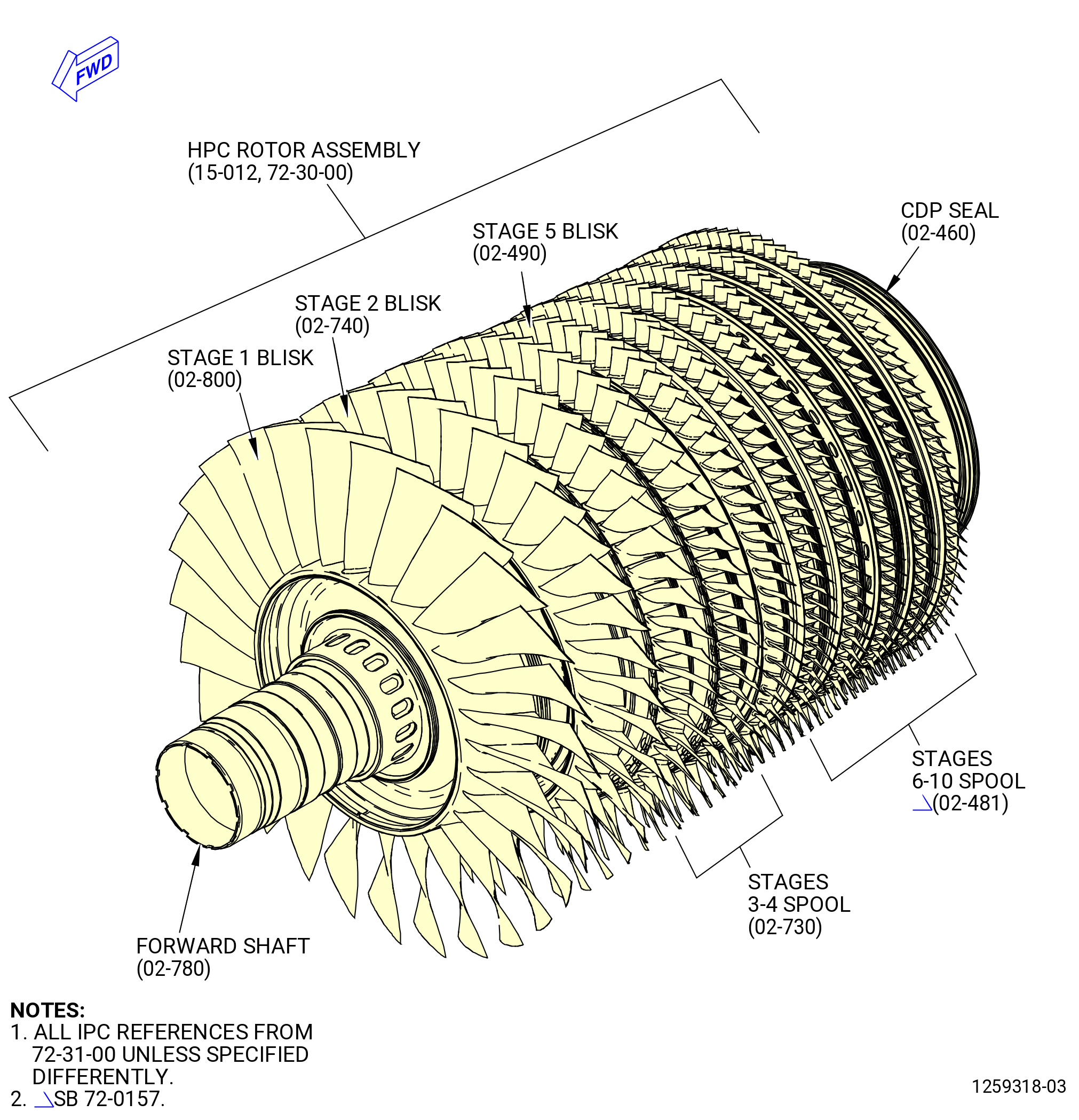
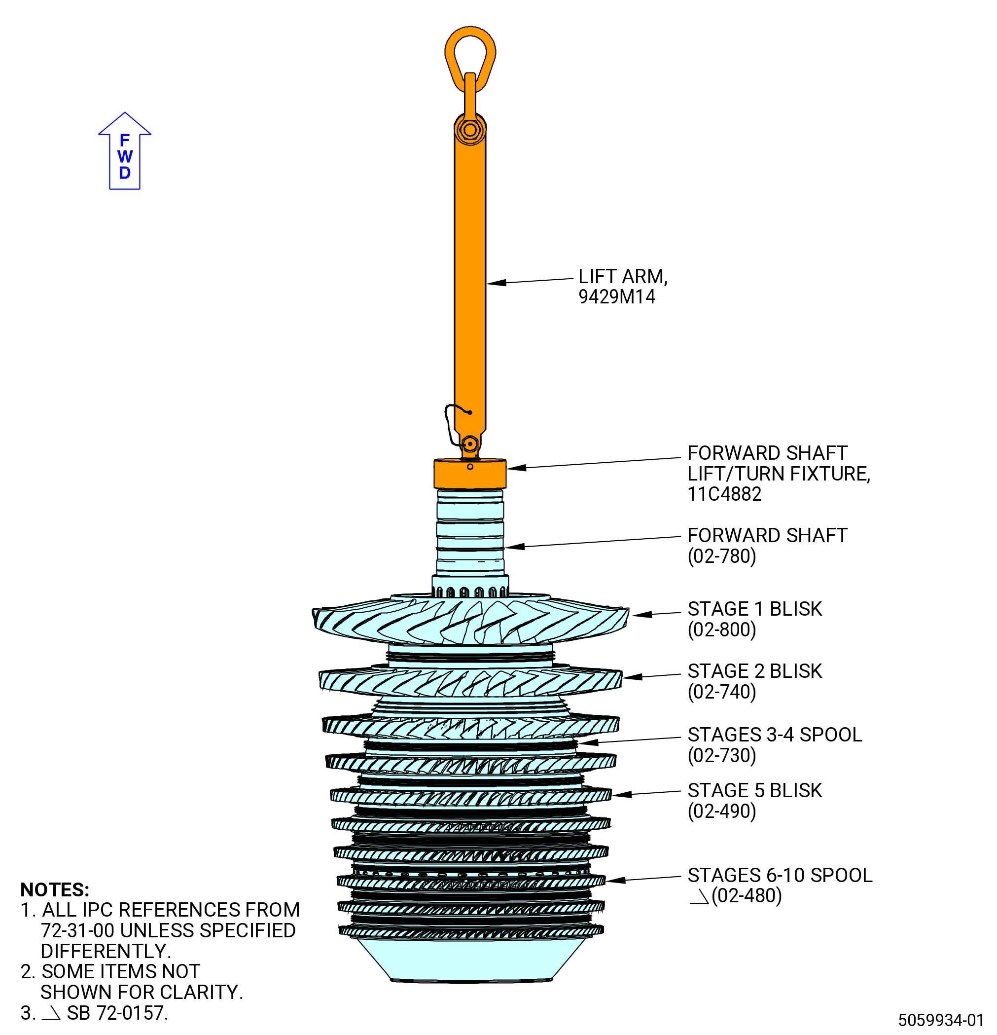
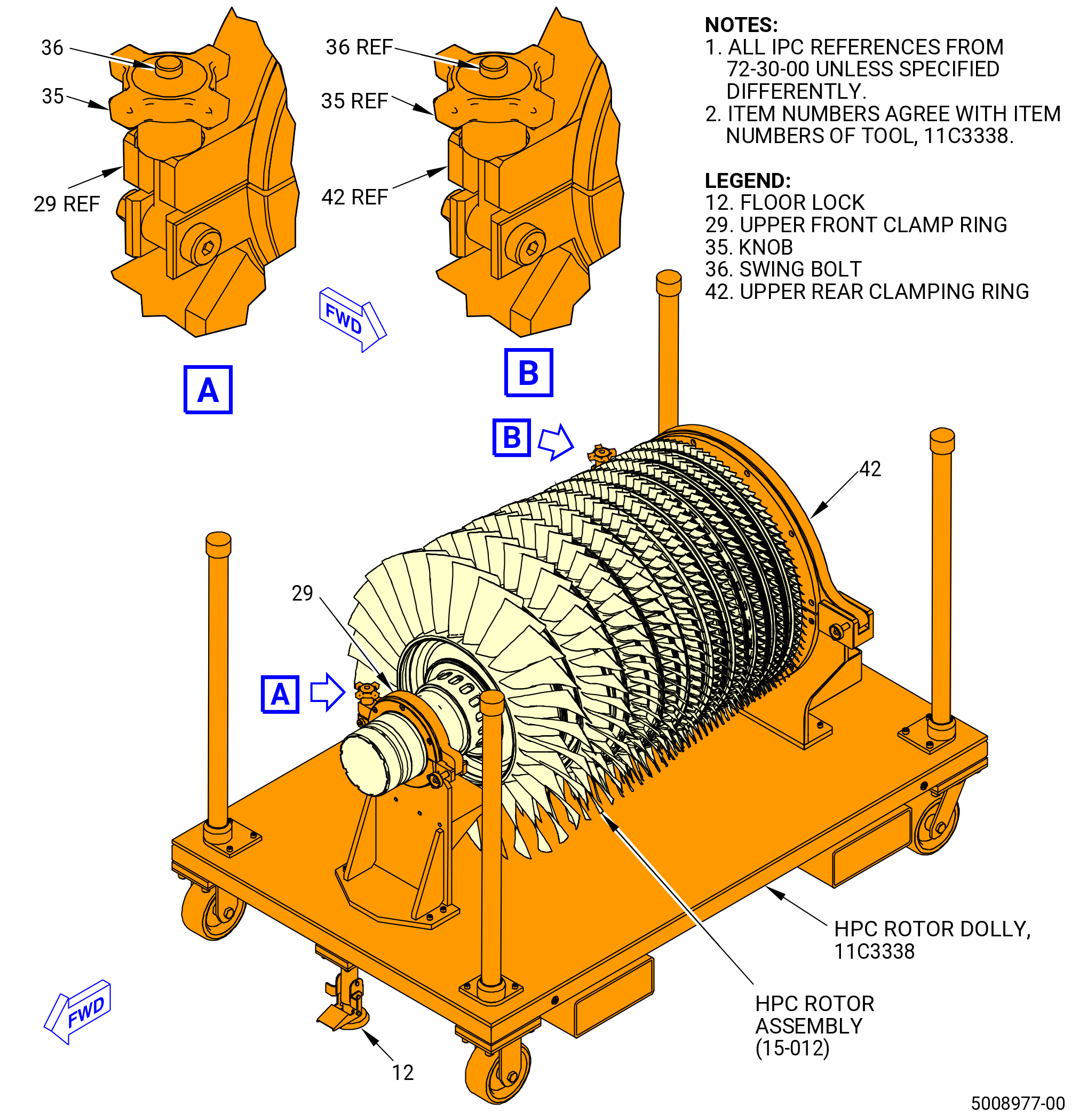
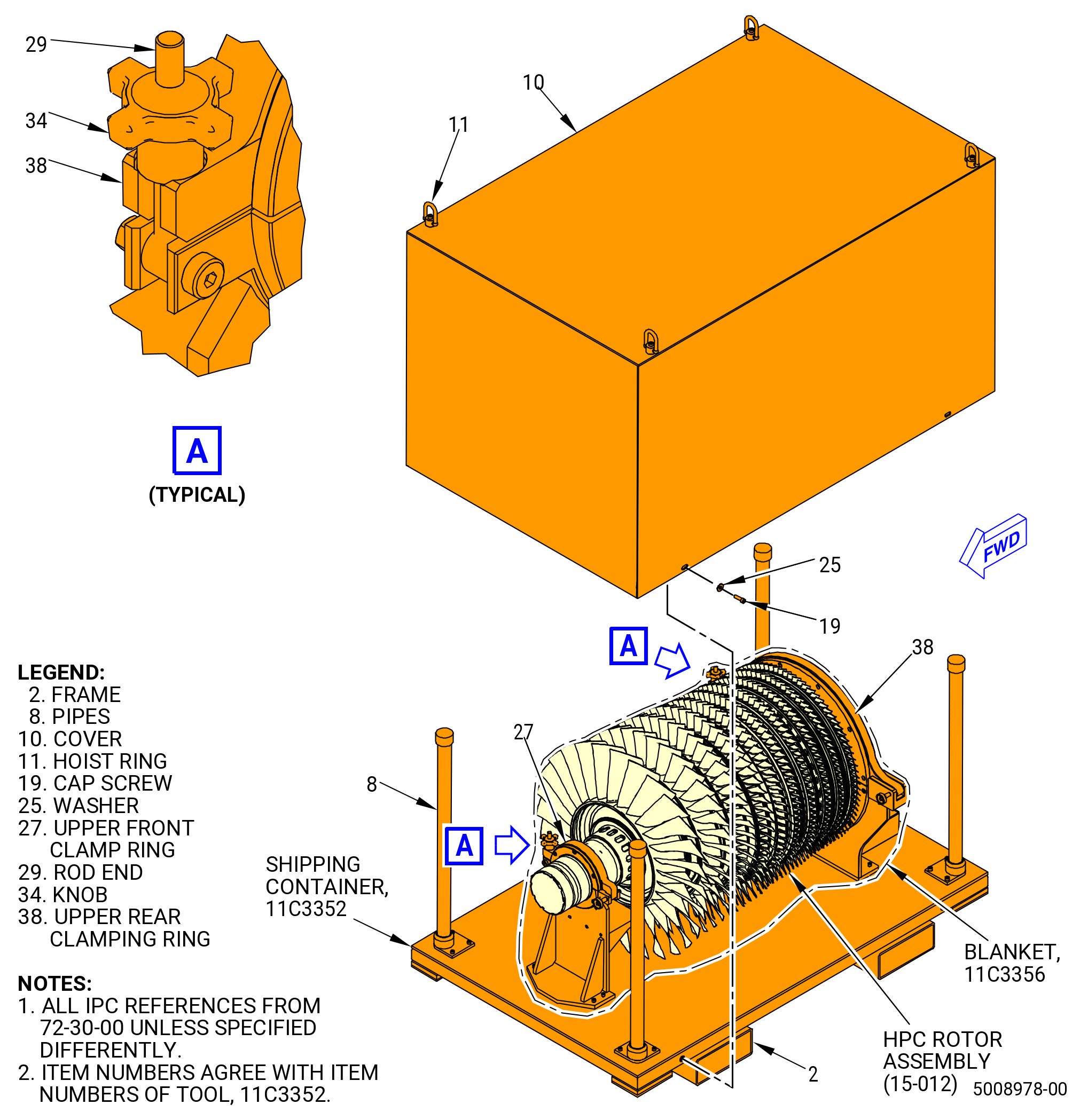
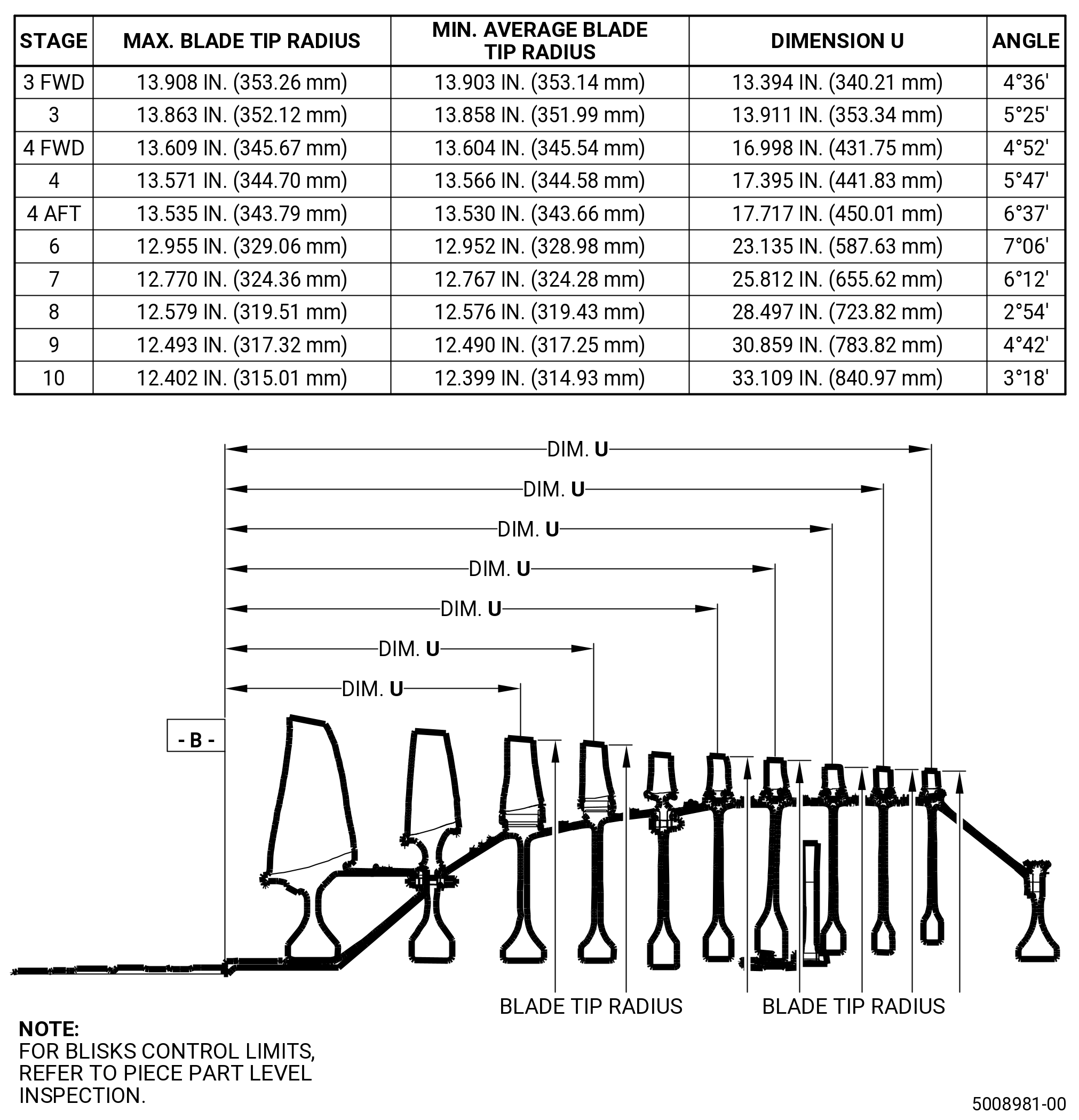
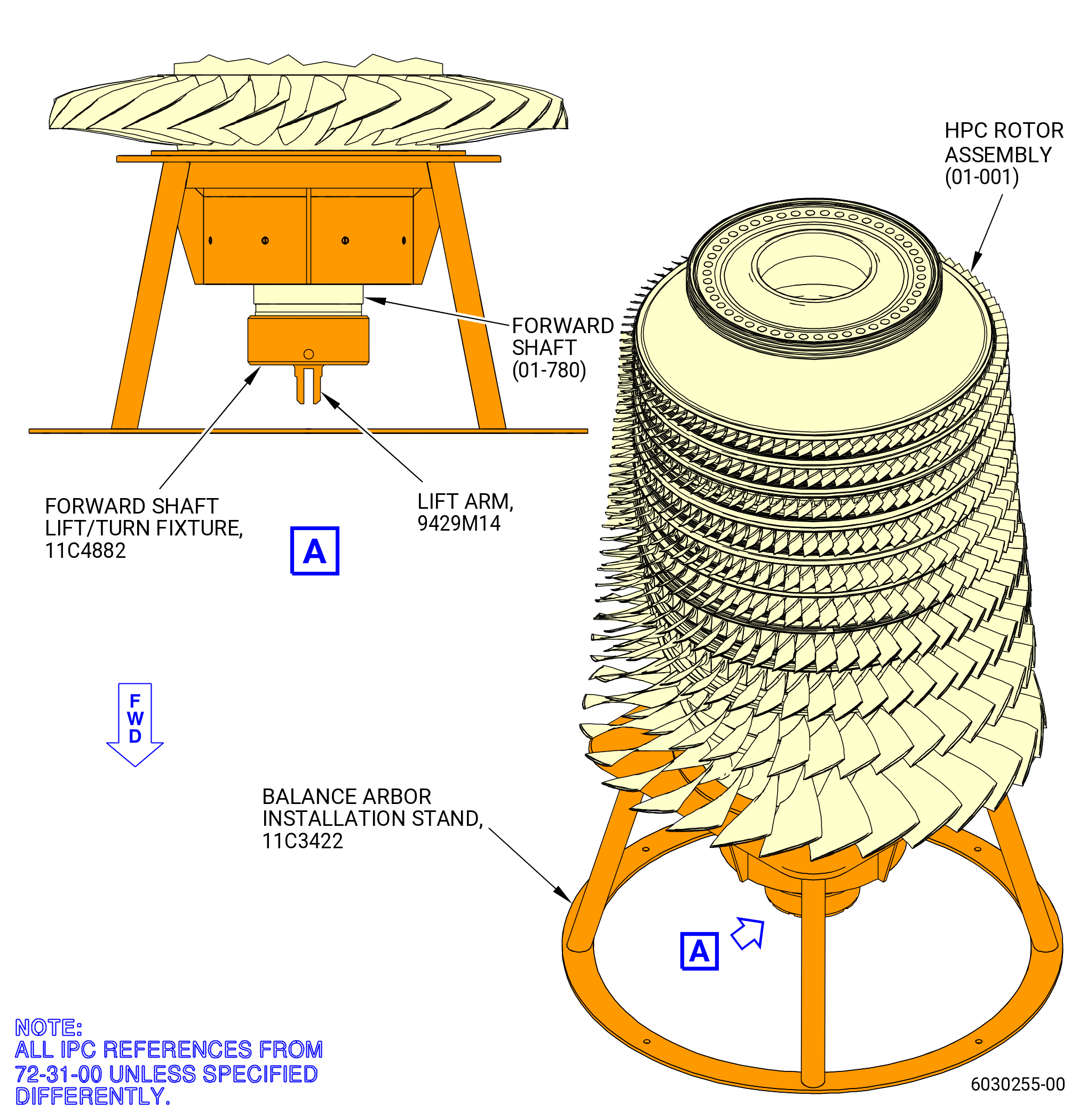
| A. | This procedure gives instructions to assemble the high pressure compressor (HPC) rotor assembly (15-012 , 72-30-00) (SIN 05000). Refer to Figure 1001. |
| B. | Instructions for the rotor components inspection system (GENSPEC), balance equipment, and tooling are supplied by the manufacturer. |
| C. | Read this procedure and become familiar with the instructions and special tools before assembling the HPC rotor assembly. |
| D. | This procedure has many hoisting/lifting procedures. Make sure to work in an area that has a minimum of two hoists, and that personnel are instructed on how to operate the hoists correctly. |
| E. | This procedure has many heating/cooling procedures. Make sure to have an oven/heat gun and freezer/dry ice supply. Make sure that you have the necessary protective material for personnel. |
| 2 . | Tools, Equipment, and Materials. |
| NOTE: |
|
| A. | Tools and Equipment. |
| (1) | Special Tools. |
| (2) | Standard Tools and Equipment. |
|
| (3) | Locally Manufactured Tools. None. |
| B. | Consumable Materials. |
|
| C. | Referenced Procedures. |
|
| D. | Expendable Parts. |
|
| 3 . | Procedure. |
| Subtask 72-31-00-440-225 |
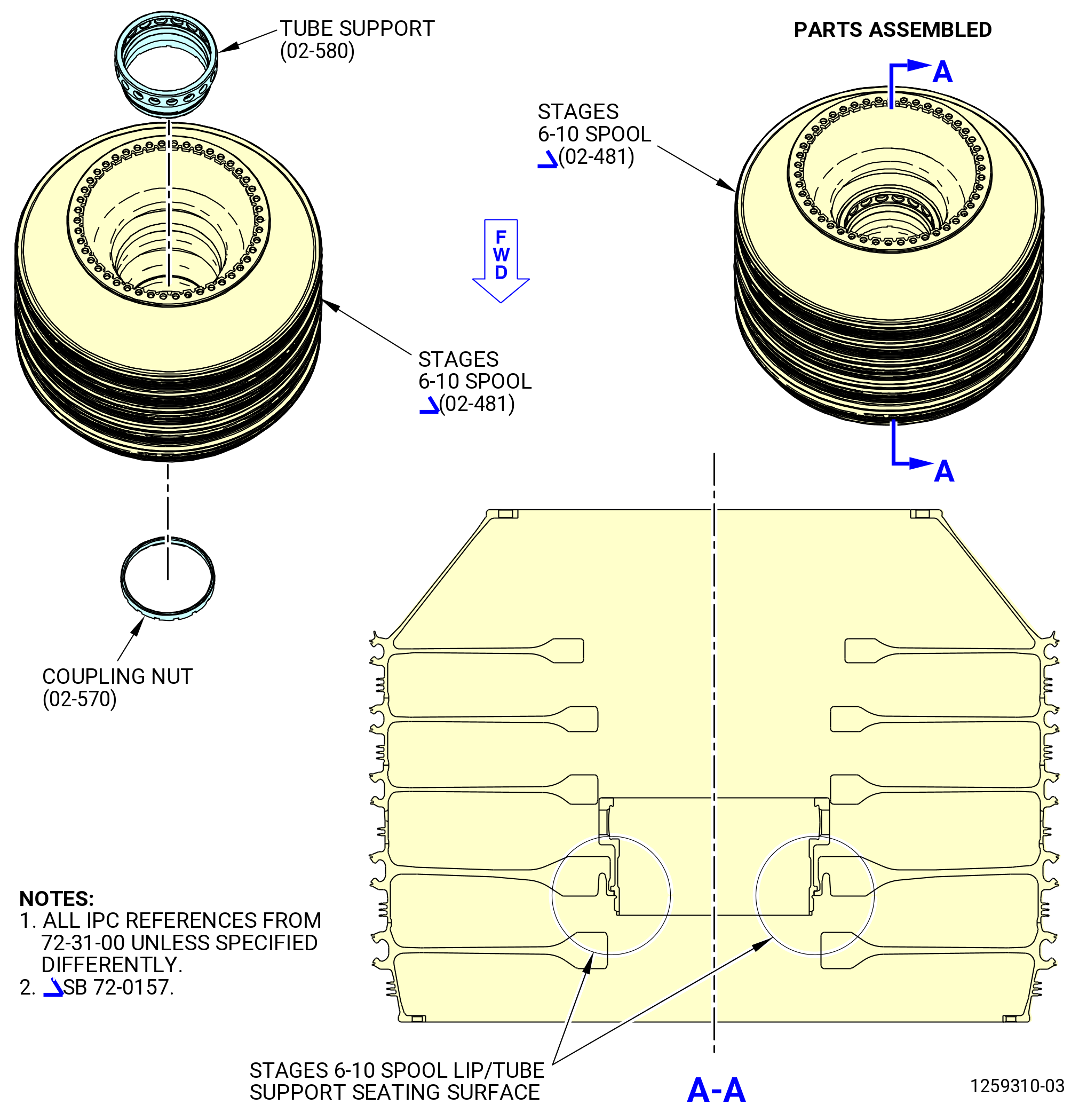
| A. | Prepare the stages 6-10 compressor rotor spool (stages 6-10 spool) (02-481) (SIN 050AR). Refer to Figure 1003 and do as follows: |
| Subtask 72-31-00-160-015 |
| WARNING: |
|
| (1) | Use C04-035 isopropyl alcohol, C04-002 Stoddard solvent, or a 50-50 blend of C04-035 isopropyl alcohol and C04-228 denatured alcohol to clean the threads and seating surfaces of the tube support (02-580) (SIN 050AM). |
| (2) | Use C04-035 isopropyl alcohol, C04-002 Stoddard solvent, or 50-50 blend of C04-035 isopropyl alcohol and C04-228 denatured alcohol to clean the threads and seating surfaces of the round plain nut (coupling nut) (02-570) (SIN 050K4). |
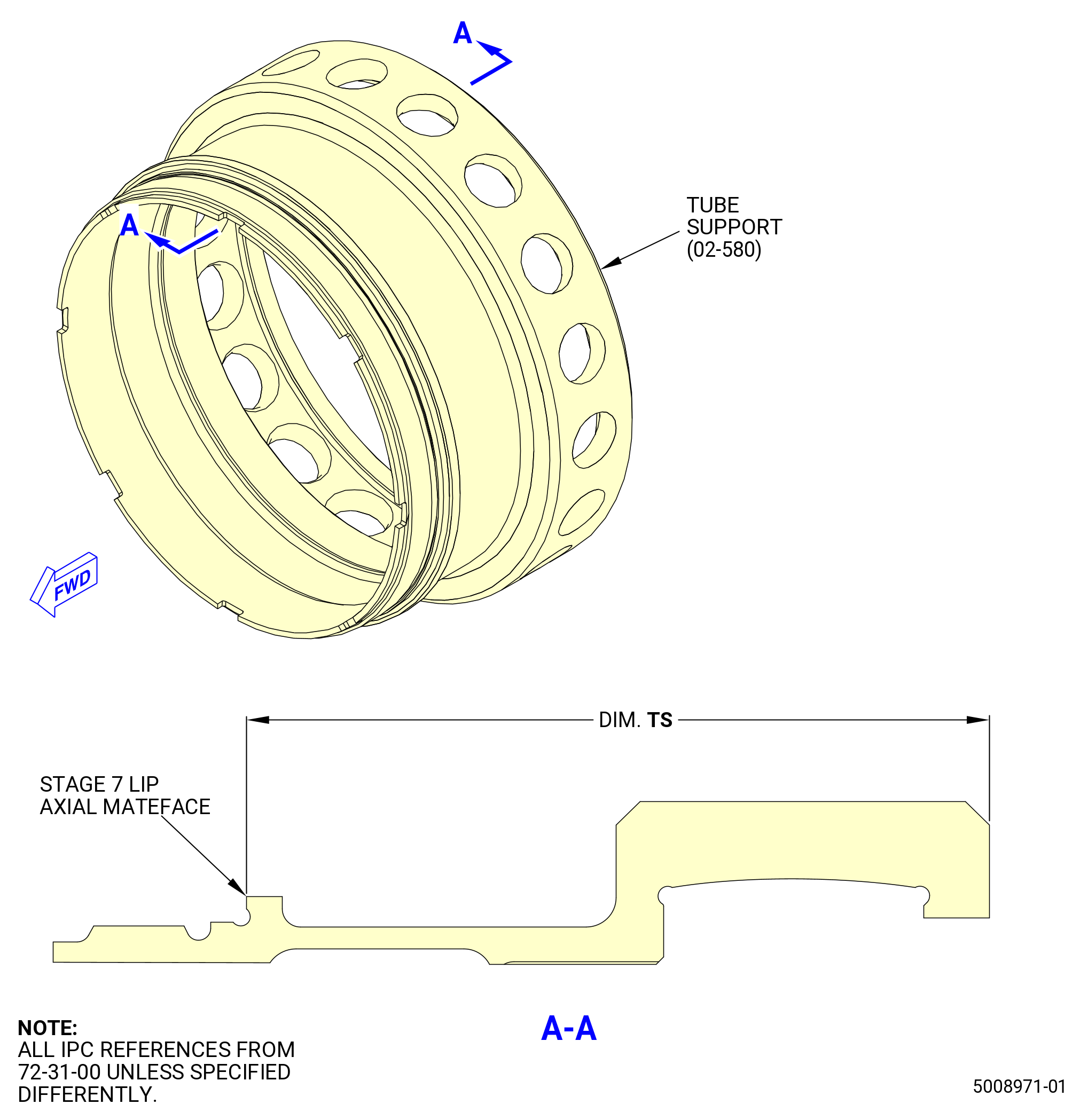
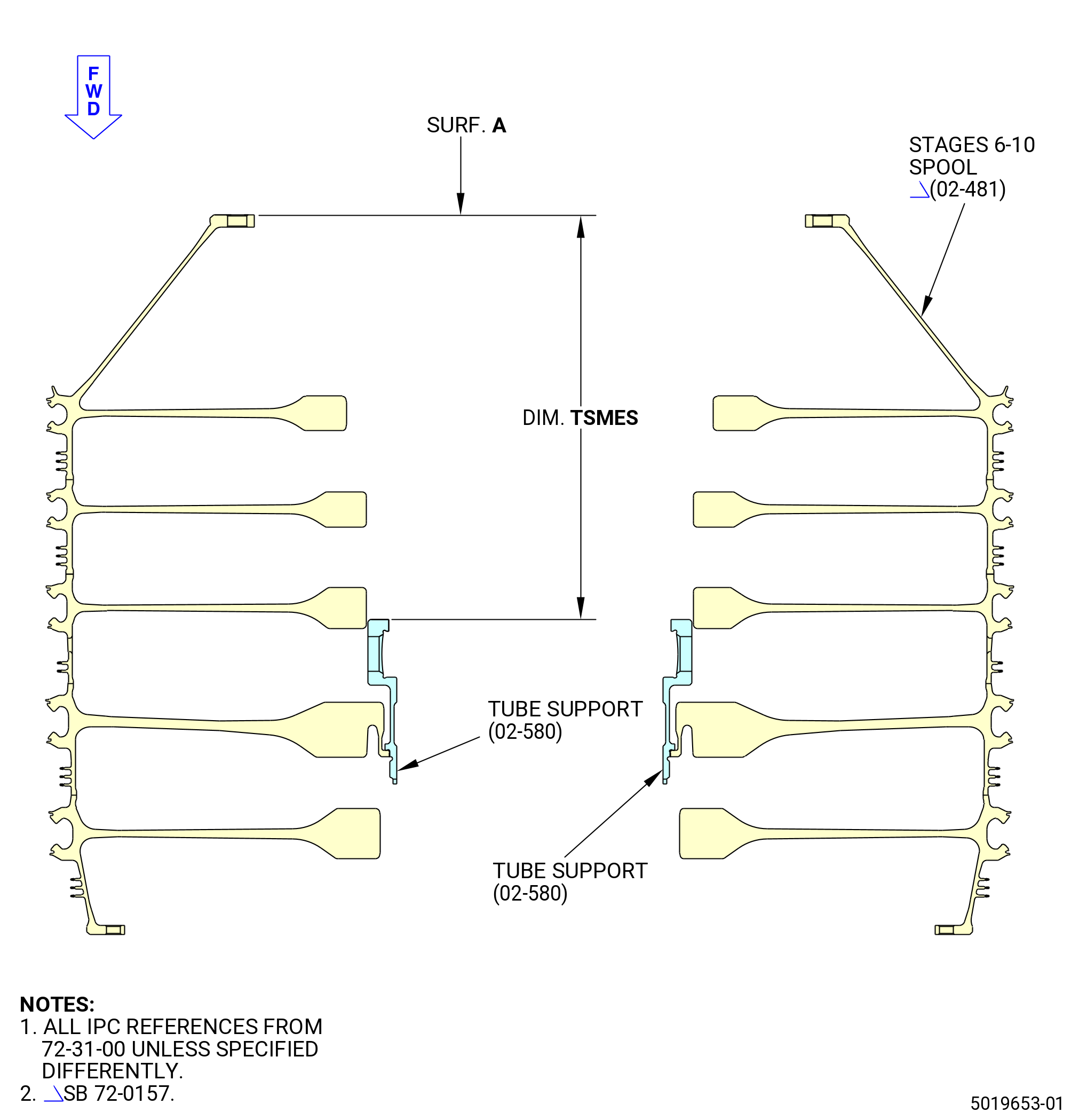
| (3) | Measure dimension TS on the tube support (02-580) (SIN 050AM). Refer to Figure 1004 and do as follows: |
| (a) | Measure the tube support from the aft face to the forward lip at four locations. The dimension TS must be 3.110-3.120 inches (78.99-79.25 mm) in length. |
| (b) | Record this measurement as dimension TS on the record sheet. Refer to Figure 1002. |
| Subtask 72-31-00-440-226 |
| (4) | Wrap the tube support (02-580) (SIN 050AM) in C10-009 greaseproof paper. |
| WARNING: |
|
| (5) | Put the tube support (02-580) (SIN 050AM) in dry ice for 30 minutes to decrease the temperature. |
| Subtask 72-31-00-440-227 |
| (6) | Put the stages 6-10 spool (02-481) (SIN 050AR) on a clean work surface and do as follows: |
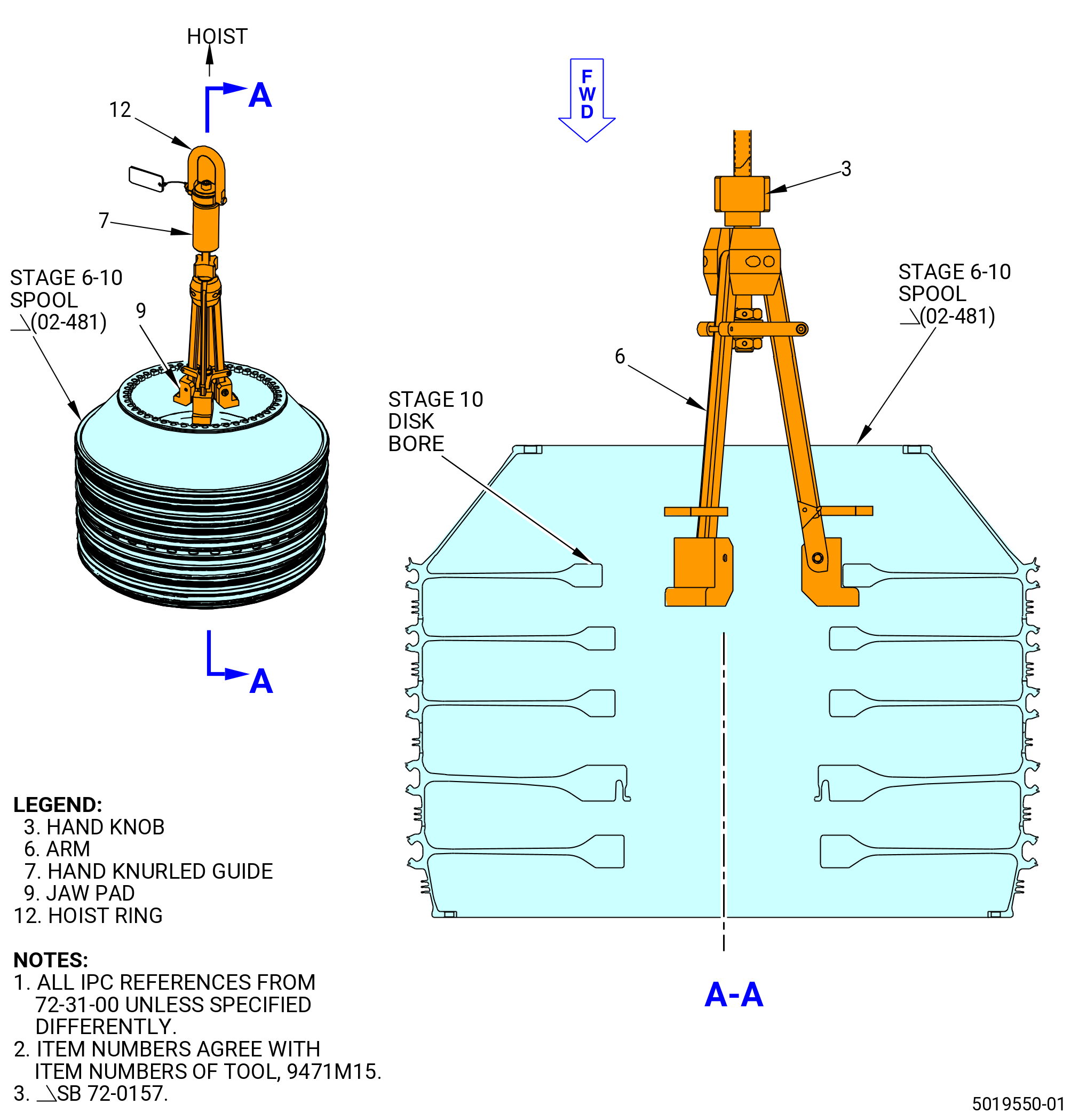
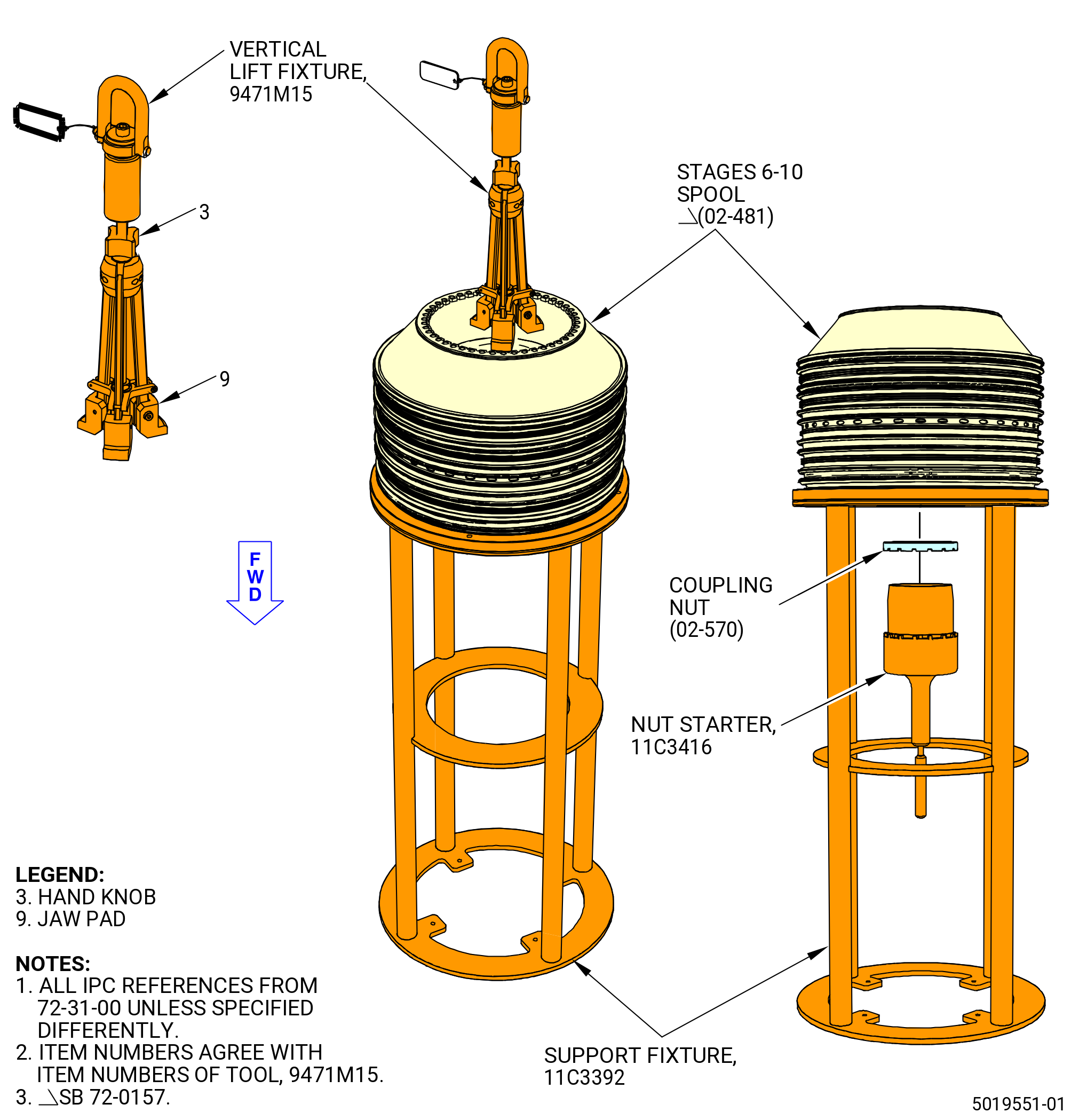
| (a) | Attach a hoist to the 9471M15 vertical lift fixture. Refer to Figure 1007 and as follows: |
| NOTE: |
|
| 1 | Attach an overhead hoist to the hoist ring (item 12). |
| 2 | Turn the hand knob (item 3) and the hand knurled guide (item 7) to let the three arms (item 6) move to the inward position. |
| WARNING: |
|
| 3 | Lift the 9471M15 vertical lift fixture and lower into the stages 6-10 spool (02-481) (SIN 050AR). |
| 4 | Turn the hand knob (item 3) clockwise (CW) to put the arms (item 6) outward on the stage 10 disk bore. Make sure that the arms (item 6) engage correctly. |
| 5 | Tighten the hand knurled guide (item 7) and the hand knob (item 3) to secure the arms (item 6). |
| (b) | Lift the stages 6-10 spool and put it on a clean work surface, forward end down. |
| (c) | Remove the 9471M15 vertical lift fixture from the stages 6-10 spool. |
| Subtask 72-31-00-160-016 |
| WARNING: |
|
| (7) | Use C04-035 isopropyl alcohol, C04-002 Stoddard solvent, or a 50-50 blend of C04-035 isopropyl alcohol and C04-228 denatured alcohol to clean the surface on the stages 6-10 spool lip at the tube support (02-580) (SIN 050AM) seating surface. Refer to Figure 1003. |
| (8) | Measure the seating flange of the tube support as follows: |
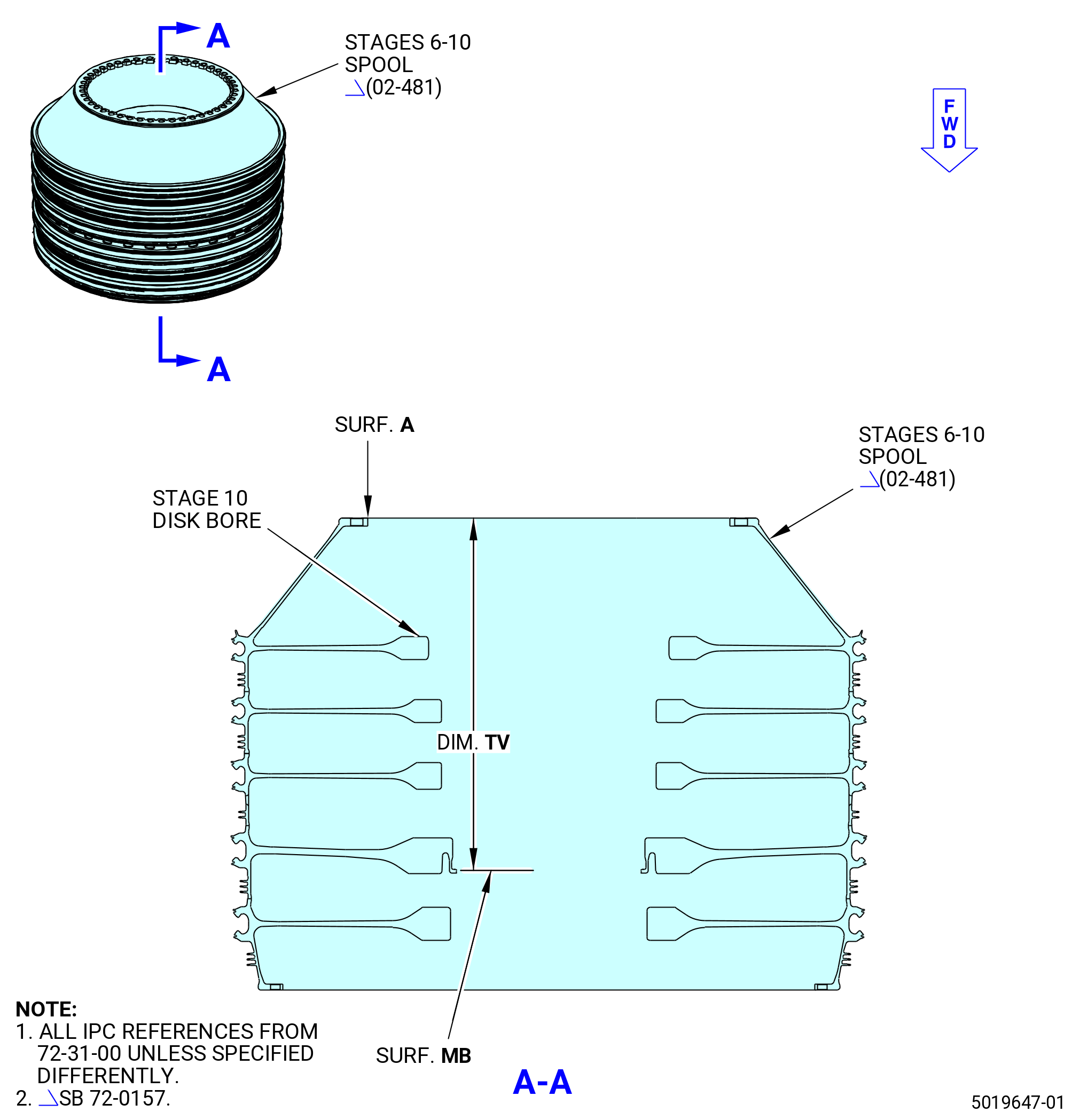
| (a) | Measure the drop dimension TV for the tube support seating flanges, from the stages 6-10 compressor rotor spool aft flange (surface A) to the tube support seating (surface MB) at four equally spaced locations. Refer to Figure 1005. |
| (b) | Record the dimensions and calculated average. Dimension TV must be 12.711-12.861 inches (322.86-326.67 mm). Refer to Figure 1002. |
| Subtask 72-31-00-440-228 |
| WARNING: |
|
| (9) | Remove the tube support (02-580) (SIN 050AM) from the dry ice. |
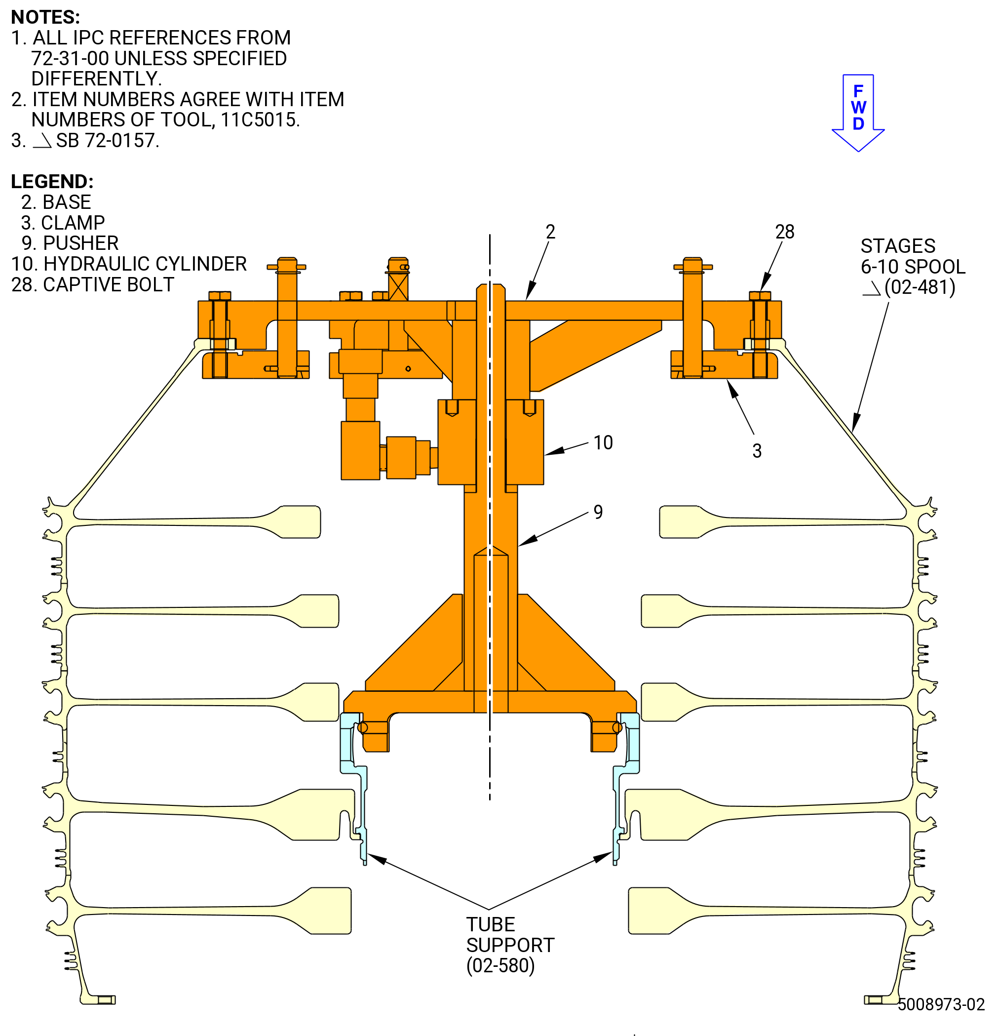
| (10) | Install the tube support ring on the stages 6-10 spool. Refer to Figure 1008 and do as follows: |
| (a) | Put the tube support ring on the forward face of the pusher (item 9) with threads facing forward and lower both into the bore of the spool. |
| (b) | Place the hydraulic cylinder (item 10) on the pusher (item 9) by hand orienting it until it seats on the pusher (item 9). |
| (c) | Loosen the six captive bolts (item 28) that attach the three clamps (item 3) on the base assembly (item 2). |
| (d) | Turn the three clamps (item 3) to the inward position to permit the installation of the 11C5015 installation/removal fixture on the stages 6-10 spool. |
| (e) | Put the 11C5015 installation/removal fixture on the aft flange of the stages 6-10 spool with the pusher (item 9) passing through the hole in the base (item 2). |
| (f) | Pivot the clamps (item 3) to the assembly position by aligning through the holes of the base (item 2). |
| (g) | Tighten the six captive bolts (item 10) to attach the 11C5015 installation/removal fixture to the stages 6-10 spool. |
| (h) | Attach a hydraulic hand pump to the 11C5015 installation/removal fixture. |
| WARNING: |
|
| (i) | Apply sufficient hydraulic pressure to push the tube support ring into place on the stages 6-10 spool. |
| (j) | Let the temperature of the tube support ring decrease to ambient temperature. |
| (k) | Release the hydraulic pressure. |
| (l) | Remove the 11C5015 installation/removal fixture. |
| (m) | Deleted. |
| Subtask 72-31-00-220-054 |
| (11) | Measure the dimension TSMES. Refer to Figure 1006 and do as follows: |
| (a) | Measure from the aft face of the stages 6-10 spool (02-481) (SIN 050AR) aft flange (surface A) to the aft face of the tube support (02-580) (SIN 050AM) at four equally spaced locations. |
| (b) | Calculate the average dimension. Dimension TSMES must be 9.591-9.751 inches (243.61-247.68 mm). |
| (c) | Record dimension TSMES on the record sheet. Refer to Figure 1002. |
| (12) | Compare the dimension TSMES to dimension TSCAL on the record sheet as follows: |
| (a) | Dimension TSMES is serviceable if dimension TSMES = TSCAL to 0.001 inch (0.03 mm) or less and do as follows: |
| 1 | If dimension TSMES is serviceable, continue with the installation of the damper tubes (02-530) (SIN 050B1) and tube impellers (02-540) (SIN 050AC). |
| 2 | If dimension TSMES is not serviceable, remove and install again the tube support. Refer to TASK 72-31-00-040-801 (72-31-00, DISASSEMBLY 001) for the tube support removal. Repeat Subtask 72-31-00-160-015 (paragraph 3.A.(3)) thru Subtask 72-31-00-220-054 (paragraph 3.A.(12)) for tube support installation. |
| Subtask 72-31-00-420-024 |
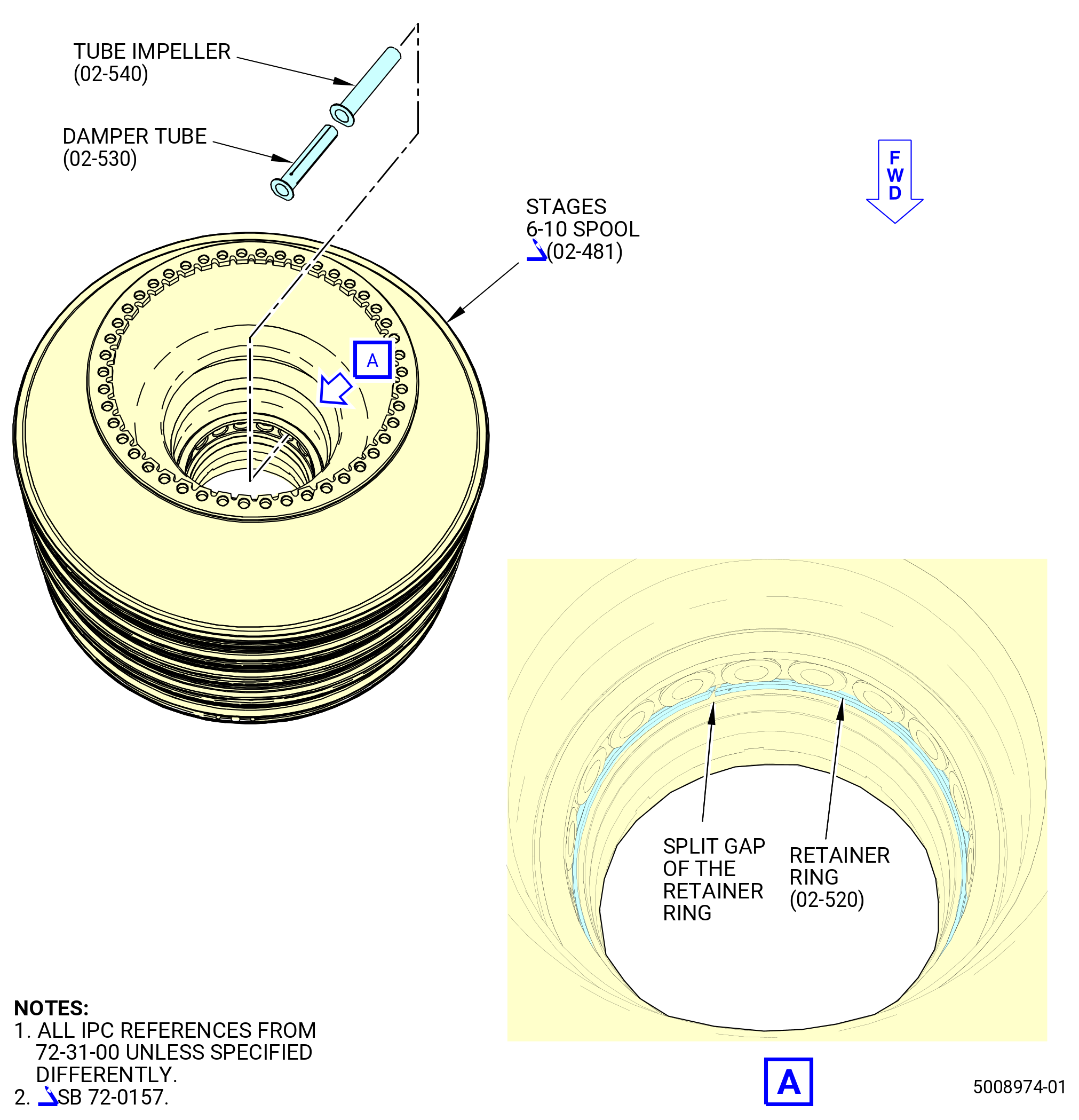
| (13) | Install the 18 damper tubes (02-530) (SIN 050B1) and tube impellers (02-540) (SIN 050AC) in the tube support (02-580) (SIN 050AM). Refer to Figure 1009 and do as follows: |
| (a) | Put the damper tubes into the tube impellers and align the flats of the two tubes together. |
| (b) | Install the damper tubes and tube impellers in the holes of the tube support (02-580) (SIN 050AM). |
| (c) | Make sure to align the flats on the tubes with the flat on the tube support. |
| NOTE: |
|
| CAUTION: |
|
| (d) | Make sure that the split gap in the retainer ring (02-520) (SIN 050AW) is not below a tube impeller and install a retainer ring between the tubes and the tube support. |
| (e) | Use a white light and inspection mirror to make sure that the retainer ring is in contact with the damper tubes around the full circumference and that it is fully seated below the flats on the damper tubes and tube impellers. Make sure that the flats of the tubes are facing forward. |
| Subtask 72-31-00-420-025 |
| (14) | Put the stages 6-10 spool on the 11C3392 support fixture. Refer to Figure 1010 and do as follows: |
| (a) | Attach a hoist to the 9471M15 vertical lift fixture. |
| (b) | Turn the hand knob (item 3) of the 9471M15 vertical lift fixture counterclockwise (CCW) to compress the three jaw pads (item 9). |
| (c) | Put the three jaw pads (item 9) in the bore of the stages 6-10 spool and on the stage 10 web. Turn the hand knob (item 3) CW to expand the jaw pads (item 9). |
| WARNING: |
|
| (d) | Lift the stages 6-10 spool and put it on the 11C3392 support fixture. |
| (e) | Remove the 9471M15 vertical lift fixture from the stages 6-10 spool. |
| WARNING: |
|
| (15) | Apply C02-058 lubricant to the threads and friction surfaces of the coupling nut (02-570) (SIN 050K4). |
| (16) | Install a coupling nut on the 11C3416 nut starter. |
| (17) | Install the 11C3416 nut starter along with the coupling nut through the center of the 11C3392 support fixture and start the threads of the coupling nut on the threads in the forward face of the tube support. Manually turn the 11C3416 nut starter and tighten the coupling nut. |
| Subtask 72-31-00-420-026 |
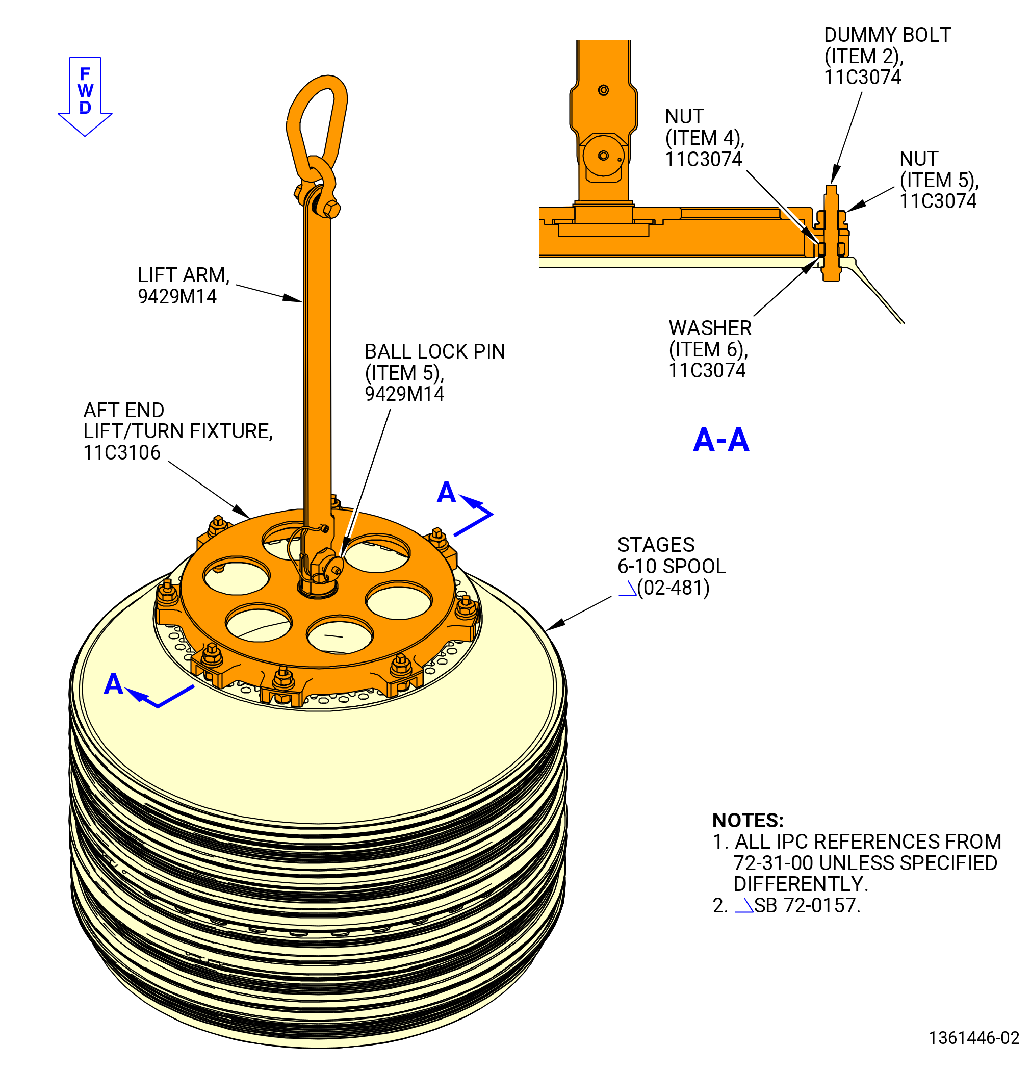
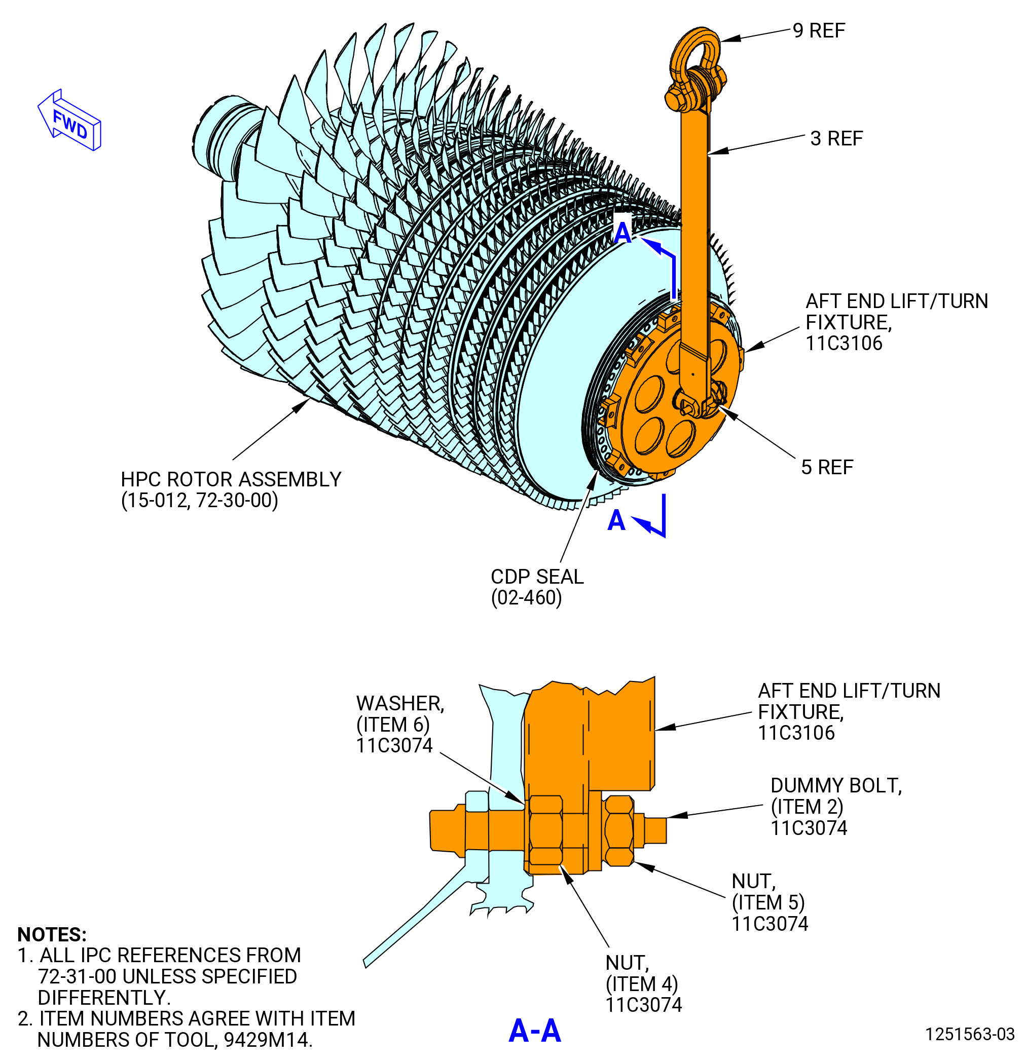
| (18) | Alternative Procedure Available. Install 11C3106 aft end lift/turn fixture on the aft flange of the stages 6-10 spool. Refer to Figure 1011 and do as follows: |
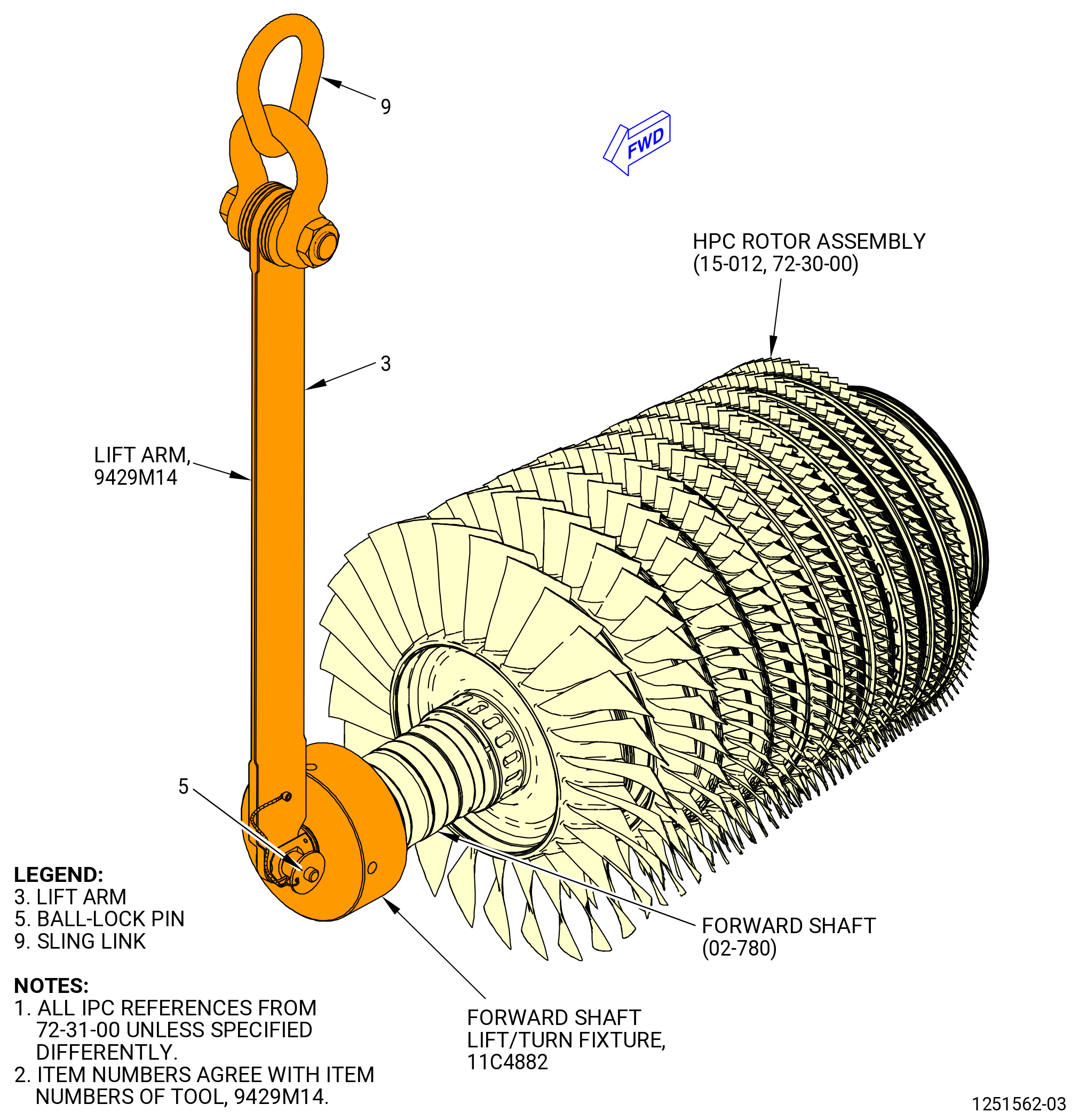
| (a) | Attach a hoist to the 9429M14 lift arm. |
| (b) | Attach the 9429M14 lift arm to the 11C3106 aft end lift/turn fixture with a ball lock pin (item 5) of the 9429M14 lift arm. |
| WARNING: |
|
| (c) | Operate the hoist to lift the 11C3106 aft end lift/turn fixture, move it above the stages 6-10 spool aft flange and lower it on the flange. |
| (d) | Attach the 11C3106 aft end lift/turn fixture to the aft flange of the stages 6-10 spool with eight dummy bolts (item 2), washers (item 6), nuts (item 4), and nuts (item 5) of the 11C3074 dummy bolt tool kit. |
| Subtask 72-31-00-420-027 |
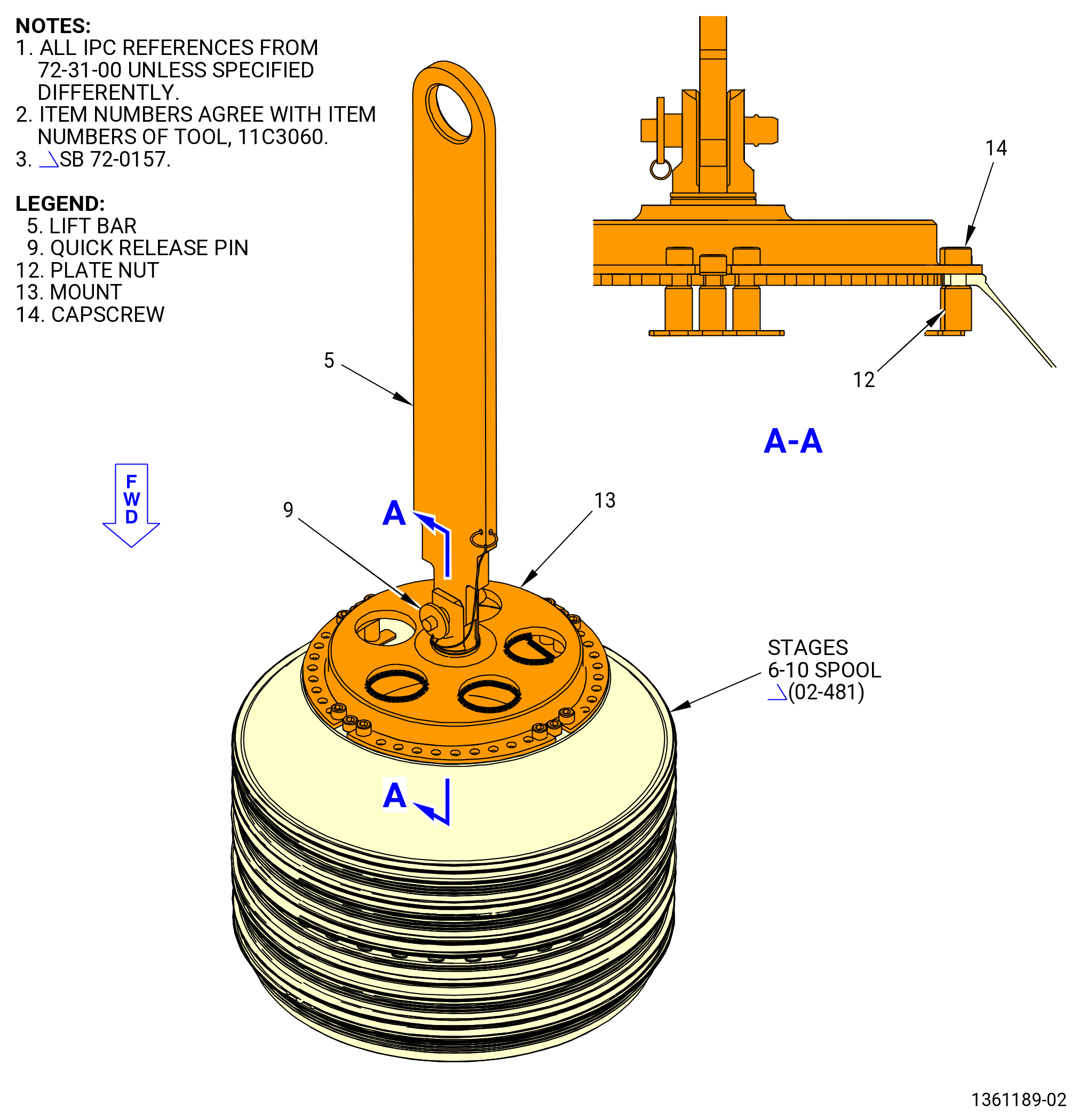
| (18).A. | Alternative Procedure. Install the 11C3060 lift/turn fixture on the aft flange of the stages 6-10 spool. Refer to Figure 1012 and do as follows: |
| (a) | Attach the four plate nuts (item 12) to the stages 6-10 spool aft flange with four capscrews (item 14). Make sure the center bolthole in the plate nuts (item 12) are 90 degrees apart on the stages 6-10 spool aft flange. |
| (b) | Attach a hoist to the lift bar (item 5). Make sure the lift bar (item 5) is attached to the mount (item 13) with the quick release pin (item 9). |
| WARNING: |
|
| (c) | Operate the hoist to lift the 11C3060 lift/turn fixture and move it above the stages 6-10 spool aft flange and lower it on the flange. |
| (d) | Attach the mount (item 13) to the stages 6-10 spool aft flange with eight capscrews (item 14). |
| Subtask 72-31-00-420-028 |
| WARNING: |
|
| (19) | Operate the hoist and lift the stages 6-10 spool from the 11C3392 support fixture. Move the stages 6-10 spool away from the stand. |
| (20) | Install the 11C3217 lift/turn fixture on the forward flange of the stages 6-10 spool as follows: |
| (a) | Install the round (item 4), plate (item 5), plate (item 6), and capscrews (item 10) of the 11C3392 support fixture on the support (item 2). |
| (b) | Attach the 9429M14 lift arm to the 11C3217 lift/turn fixture with a ball lock pin (item 5) of the 9429M14 lift arm. |
| (c) | Put the 11C3217 lift/turn fixture on the round (item 4), plate (item 5), and plate (item 6) of the 11C3392 support fixture. |
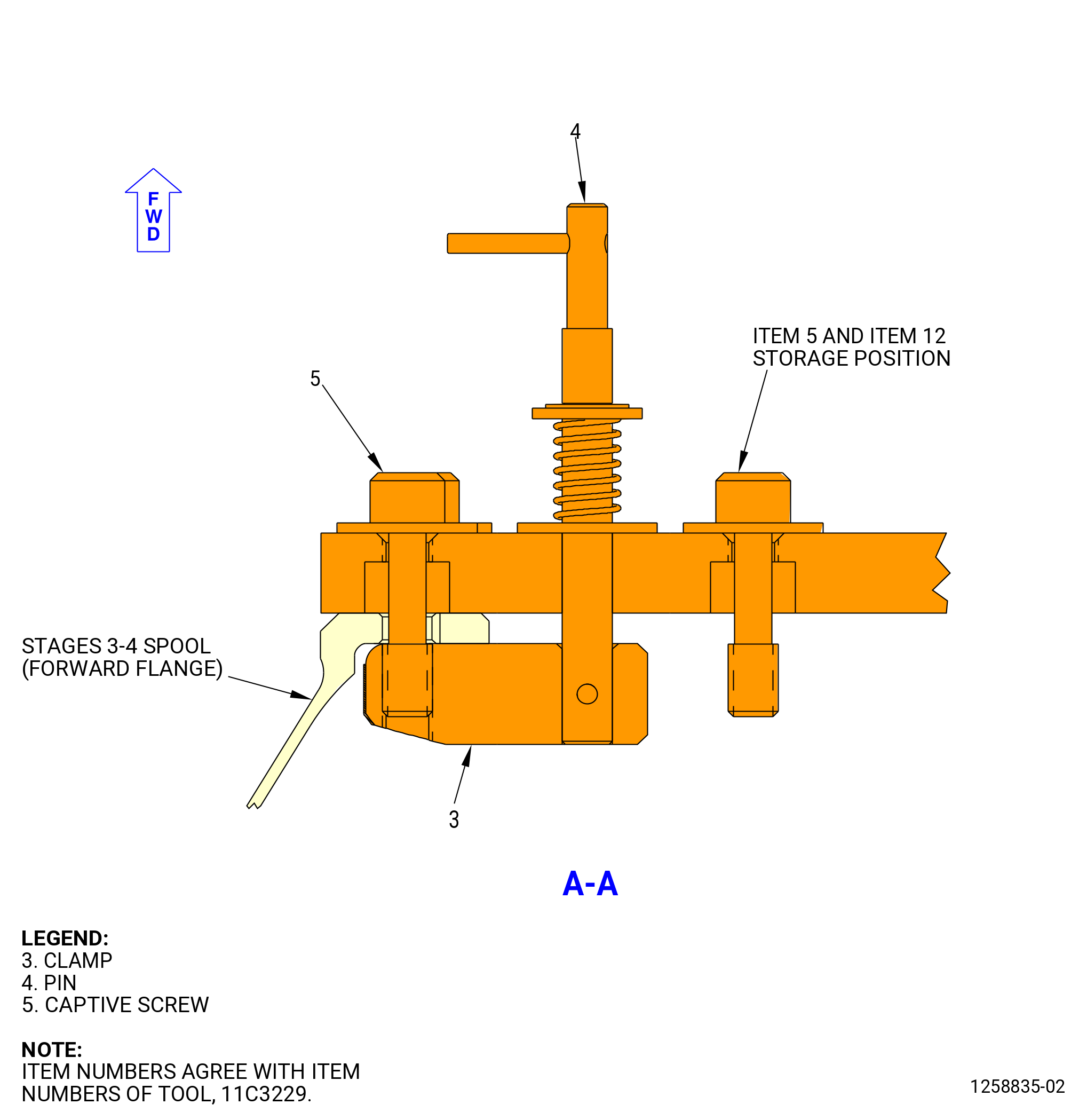
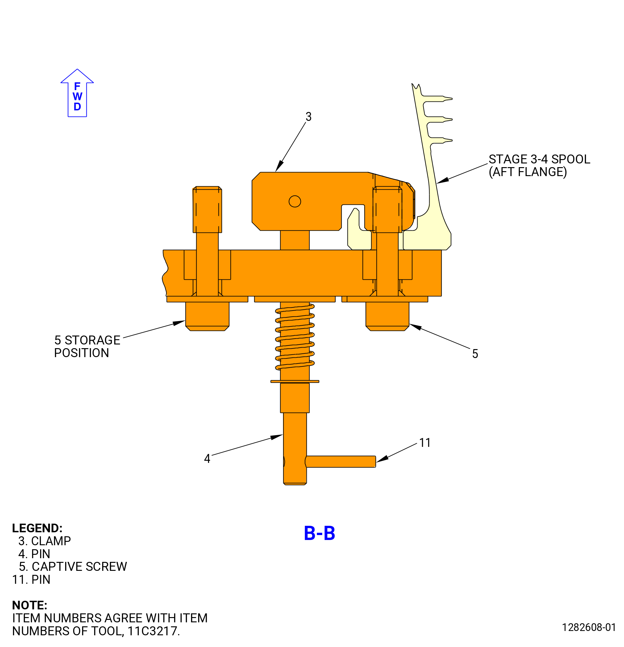
| (d) | Loosen the eight captive screws (item 5) of the 11C3217 lift/turn fixture. |
| (e) | Push the pins (item 4) in and turn to move the clamps (item 3). |
| (f) | Move the stages 6-10 spool above the 11C3217 lift/turn fixture and lower it onto the 11C3217 lift/turn fixture. |
| (g) | Attach the 11C3217 lift/turn fixture to the forward flange of the stages 6-10 spool as follows: |
| 1 | Push the pins (item 4) in and turn them to put the clamps (item 3) above the aft face of the forward flange. |
| 2 | Tighten the eight captive screws (item 5). |
| WARNING: |
|
| (21) | Operate the hoist and lift the stages 6-10 spool. |
| (22) | Attach one more hoist to the 9429M14 lift arm that is attached to the 11C3217 lift/turn fixture. |
| (23) | Operate the hoists to lift the forward end and lower the aft end of the stages 6-10 spool. |
| (24) | Remove the 11C3106 aft end lift/turn fixture or the 11C3060 lift/turn fixture. |
| (25) | Install the 11C3259 dummy on the aft flange of the stages 6-10 spool as follows: |
| (a) | Install the 11C3259 dummy on the stages 6-10 spool with the 23 dummy bolts (item 2), washers (item 6), and nuts (item 4) of the 11C3074 dummy bolt tool kit, boltheads forward. |
| NOTE: |
|
| (b) | Torque all 23 nuts (item 4) to 100 lb in. (11.3 N.m) in a criss-cross pattern. |
| (c) | Torque all 23 nuts (item 4) to 300 lb in. (33.9 N.m) in a criss-cross pattern. |
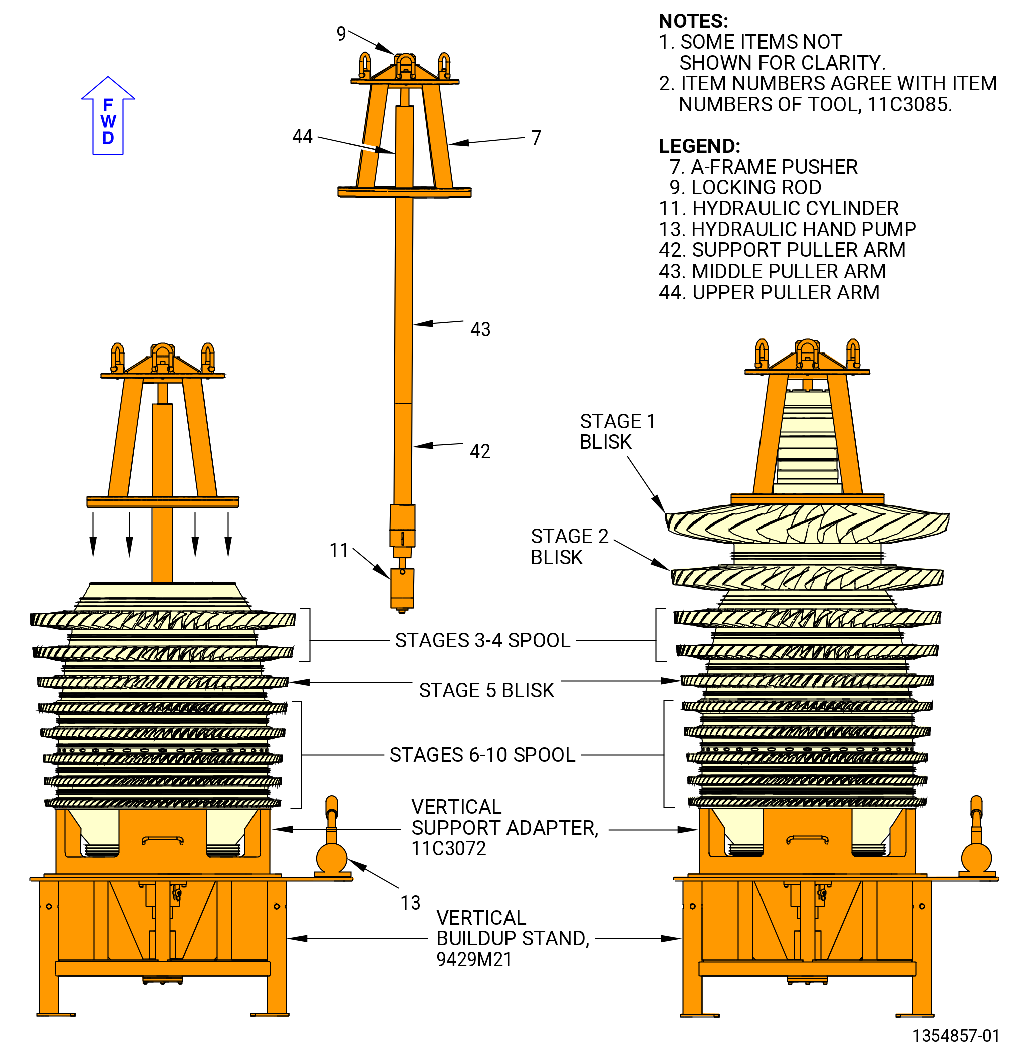
| (26) | Lower the stages 6-10 spool and put it on the 11C3072 vertical support adapter on the 9429M21 vertical build-up stand in the aft end down position. |
| (27) | Remove the 11C3217 lift/turn fixture. |
| Subtask 72-31-00-420-029 |
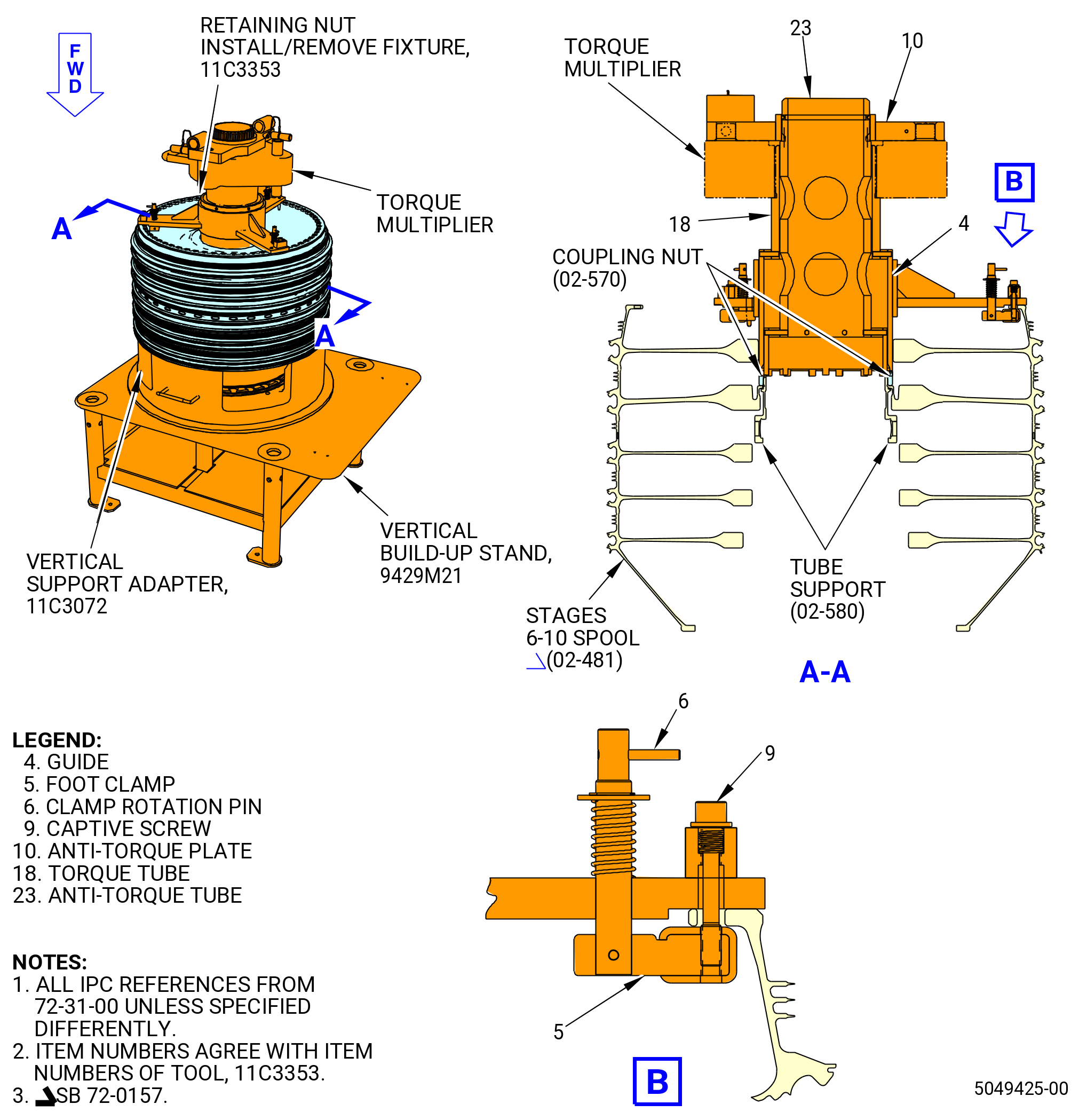
| (28) | Torque the coupling nut (02-570) (SIN 050K4). Refer to Figure 1013 and do as follows: |
| (a) | Install the 11C3353 retaining nut install/remove fixture on the forward face of the stages 6-10 spool as follows: |
| NOTE: |
|
| 1 | Loosen the three captive screws (item 9). |
| 2 | Turn the three clamp rotation pins (item 6) to move the foot clamps (item 5). |
| 3 | Put the guide (item 4) on the forward face of the stages 6-10 spool. |
| 4 | Turn the three clamp rotation pins (item 6) to move the foot clamps (item 5) below the aft face of the forward flange. |
| 5 | Tighten the three captive screws (item 9) to secure the foot clamps (item 5). |
| 6 | Put the anti-torque tube (item 23) through the center of the guide (item 4) and engage the castellations of the anti-torque tube (item 23) with the slots of the tube support ring. |
| 7 | Put the torque tube (item 18) through the center of the guide (item 4) and above the anti-torque tube (item 23). Engage the castellations of the torque tube (item 18) with the slots of the coupling nut. |
| 8 | Install the torque multiplier with the lugs in the up position, on the torque tube (item 18). |
| 9 | Align the splines of the anti-torque plate (item 10) with the splines of the anti-torque tube (item 23) and put it on the torque multiplier. Make sure that the holes in the anti-torque plate (item 10) are above the pins of the torque multiplier. |
| (b) | Torque the coupling nut to 1700 lb ft (2304 N.m). |
| (c) | Remove the anti-torque plate (item 10) of the torque multiplier, torque tube (item 18), and anti-torque tube (item 23). |
| (d) | Make sure that the slots of the coupling nut and the tube support are aligned to let the installation of the key ring (02-560) (SIN 050V0). |
| (e) | If the slots of the coupling nut and tube support are not aligned, install the torque tube (item 18), anti-torque tube (item 23), torque multiplier, and anti-torque plate (item 10) again. |
| CAUTION: |
|
| (f) | If necessary, torque the coupling nut to a maximum of 2000 lb ft (2711 N.m). Use only as much torque as necessary to align the slots of the coupling nut and the tube support to let the installation of the key ring (02-560) (SIN 050V0). |
| (g) | Remove the 11C3353 retaining nut install/remove fixture and torque multiplier. |
| (29) | Install the key ring (02-560) (SIN 050V0) with the outer lug engaged in one of the slots on the coupling nut and the inner lug engaged in one of the slots on the tube support. |
| (30) | Install the ring (02-550) (SIN 050V1) in the groove of the coupling nut. |
| (31) | Make sure that the ring is correctly seated in the groove of the coupling nut. |
| Subtask 72-31-00-440-229 |
| B. | Install the blades in the stages 6-10 spool as follows: |
| (1) | Install the 11C3217 lift/turn fixture on the forward flange of the stages 6-10 spool (02-481) (SIN 050AR) as follows: |
| (a) | Loosen the eight captive screws (item 5). |
| (b) | Push the pins (item 4) in and turn them to move the clamps (item 3). |
| (c) | Attach a hoist to the 9429M14 lift arm that is attached to the 11C3217 lift/turn fixture. |
| WARNING: |
|
| (d) | Move the 11C3217 lift/turn fixture above the stages 6-10 spool. |
| (e) | Lower the 11C3217 lift/turn fixture on the forward flange of the stages 6-10 spool. |
| (f) | Push the pins (item 4) in and turn them to put the clamps (item 3) above the aft face of the forward flange. |
| (g) | Tighten the eight captive screws (item 5). |
| WARNING: |
|
| (2) | Operate the hoist and lift the stages 6-10 spool from the 11C3072 vertical support adapter. |
| (3) | Remove the 11C3259 dummy from the aft flange of the stage 6-10 spool. |
| (4) | Install the 11C3106 aft end lift/turn fixture or the 11C3060 lift/turn fixture on the aft flange of the stages 6-10 spool. Refer to Subtask 72-31-00-420-026 (paragraph 3.A.(16)) or Subtask 72-31-00-420-027 (paragraph 3.A.(16)A.) . |
| WARNING: |
|
| (5) | Operate the hoists to lift the aft end and lower the forward end of the stages 6-10 spool. |
| (6) | Remove the 11C3217 lift/turn fixture from the stages 6-10 spool. |
| (7) | Put the stages 6-10 spool on a clean work surface, forward end down. |
| (8) | Remove the 11C3106 aft end lift/turn fixture or the 11C3060 lift/turn fixture from stages 6-10 spool. |
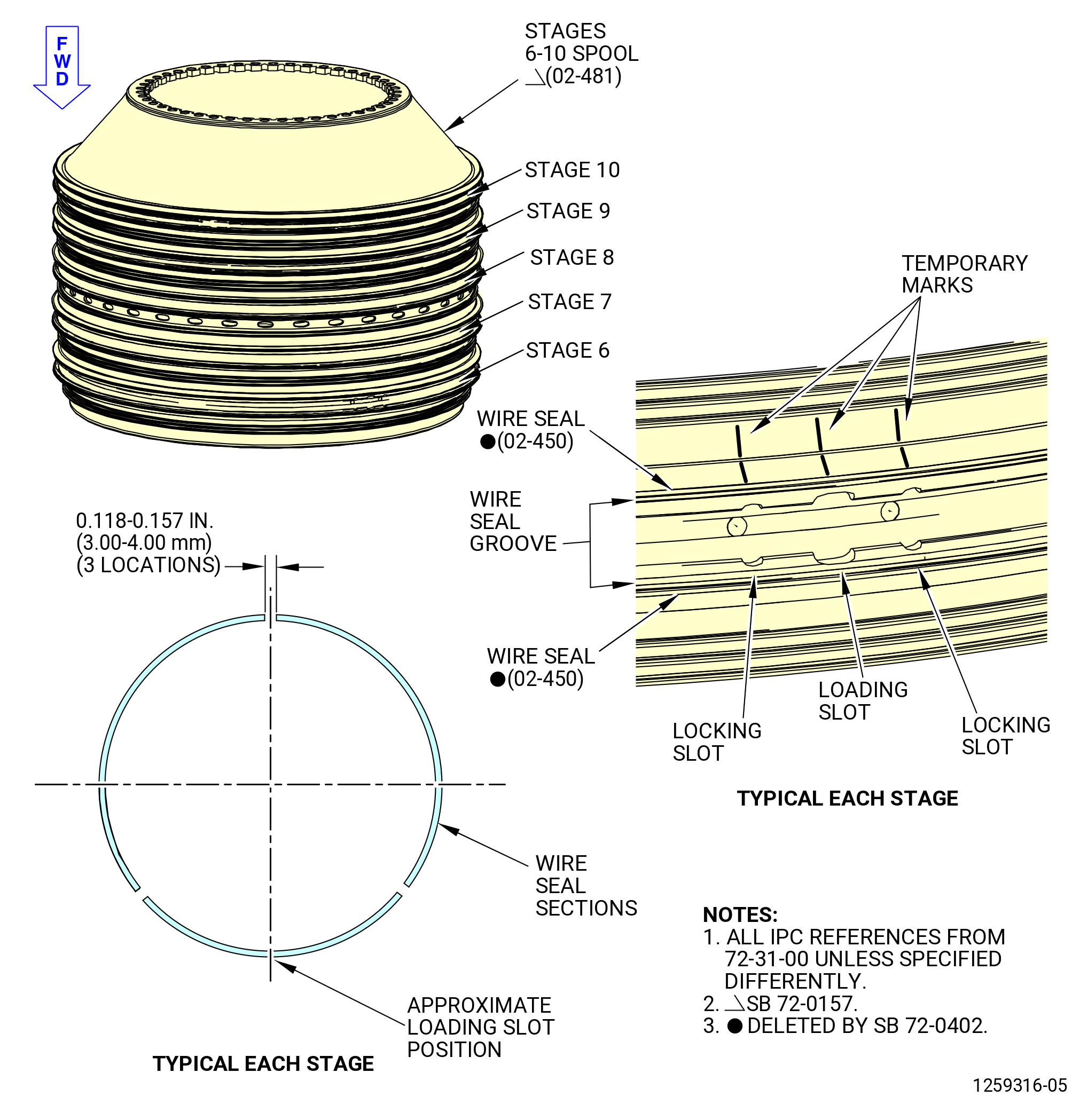
| (9) | Use a C05-003 marking pen to put a mark on the stages 6-10 spool to identify the loading slot and the locking slot locations on stages 6 thru 10. Refer to TASK 70-16-02-350-017 (TEMPORARY MARKING) and Figure 1014. |
| Subtask 72-31-00-440-298 |
| * * * PRE SB 72-0402( HPC Rotor Assembly with Wire Seals ) |
| (10) | Install the wire seals (02-450) (SIN 050N0) and (02-440) (SIN 050N1) in the forward and aft groove of stage 6 on the stages 6-10 spool as follows: |
| NOTE: |
|
| (a) | Install the wire seal (02-450) (SIN 050N0) in the forward groove. Cut the wire seal to fit in the forward groove. |
| (b) | Install the wire seal (02-440) (SIN 050N1) in the aft groove. Cut the wire seal to fit in the aft groove. |
| (c) | Remove the wire seals from the forward and aft grooves and cut each of them in three equal sections. |
| (d) | Make sure that the wire seal sections do not have burrs or sharp edges. |
| (e) | Put one of the wire seal sections in the forward groove so that the loading slot is at the center of the wire seal section. Push the wire seal section around the perimeter of the stages 6-10 spool while inserting the other two wire seal sections in the forward groove after the first wire seal section. |
| (f) | Put one of the wire seal sections in the aft groove so that the loading slot is at the center of the wire seal section. Push the wire seal section around the perimeter of the stages 6-10 spool while inserting the other two wire seal sections in the aft groove after the first wire seal section. |
| (g) | Adjust the gaps between the ends of each wire seal section in the forward and aft grooves to 0.118-0.157 inch (3.00-4.00 mm). Refer to Figure 1014. |
| WARNING: |
|
| (h) | Attach the ends of the wire seal sections to the stages 6-10 spool with C01-027 adhesive, C10-109 utility wax, or C01-057 adhesive. |
| Subtask 72-31-00-160-017 |
| (i) | Use C04-035 isopropyl alcohol to clean the wire seal. |
| Subtask 72-31-00-440-230 |
| (j) | Install three stage 6 blades above the ends of the wire seal sections to hold them in position. |
| (k) | Remove the stage 6 blades from the spool when the adhesive is cured. |
| (l) | Make sure that the ends of the wire seal sections are not above the grooves. |
| * * * END PRE SB 72-0402 |
| Subtask 72-31-00-420-030 |
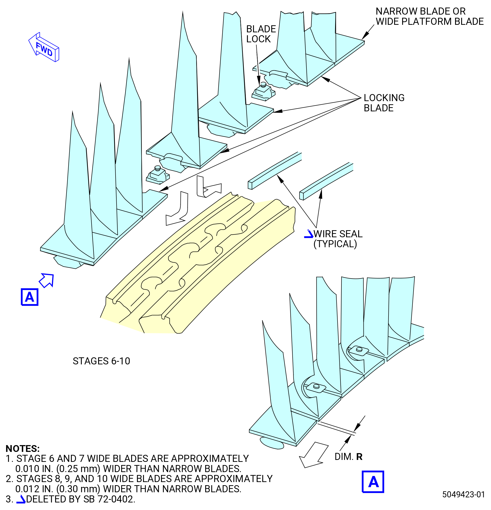
| (11) | Install the stage 6 blades (02-400) (SIN 057A6), (02-410) (SIN 057AD), (02-390) (SIN 057AE), and (02-380) (SIN 057AF). Refer to Figure 1015 and do as follows: |
| (a) | Use a C05-003 marking pen to put a W mark (meaning WIDE) on 30 stage 6 blades (02-410) (SIN 057AD). Refer to TASK 70-16-02-350-017 (TEMPORARY MARKING). |
| NOTE: |
|
| (b) | Install 33 narrow stage 6 blades (02-400) (SIN 057A6) in the stages 6-10 spool in a CCW aft looking forward (ALF) direction. |
| (c) | Install 39 wide stage 6 blades (02-410) (SIN 057AD) in the stages 6-10 spool in a CCW ALF direction. |
| Subtask 72-31-00-420-031 |
| (d) | Install four stage 6 blades (02-390) (SIN 057AE), (02-380) (SIN 057AF) as follows: |
| 1 | Install one stage 6 blade (02-390) (SIN 057AE) and one stage 6 blade (02-380) (SIN 057AF) with the slot in the blade platforms to the stage 6 loading slot of the stages 6-10 spool. |
| 2 | Install one stage 6 blade (02-380) (SIN 057AF) against the stage 6 blade (02-390) (SIN 057AE) so the slots face each other. |
| NOTE: |
|
| 3 | Install one stage 6 locking blade (02-390) (SIN 057AE) against the stage 6 locking blade (02-380) (SIN 057AF) so the slots face each other. |
| 4 | Move the full amount of stage 6 blades CCW to make sure that the last stage 6 locking blade installed does not fall out. |
| 5 | Make sure that the platforms of the blades do not overlap. |
| 6 | Move the full amount of stage 6 blade CW to let the removal of the two-inner stage 6 locking blades. |
| 7 | Align each of the two inner blades, one at a time, with the center mark on the stages 6-10 spool at the loading slot. Remove the two locking blades. |
| 8 | Install two locking lug (02-370) (SIN 050B0). Move the locking lugs to let the installation of the two-inner stage 6 blades that were removed. |
| 9 | Install the two-inner stage 6 locking blades, again. |
| 10 | Move the installed blades around in the stages 6-10 spool until the stage 6 locking lugs align with the locking slots of the stages 6-10 spool. |
| 11 | Loosen each of the locking lug setscrews. |
| 12 | Torque each of the locking lug setscrews to 6-10 lb in. (0.7-1.1 N.m) more than the run-on torque. |
| 13 | Replace a locking lug if the run-on torque of the setscrew is not in the limit of 3.5-30 lb in (0.40-3.4 N.m). |
| 14 | Make sure that the setscrews are correctly engaged. |
| NOTE: |
|
| Subtask 72-31-00-440-231 |
| (e) | Alternative Procedure Available. Manually move the stage 6 blades (02-380) (SIN 057AF), (02-390) (SIN 057AE), (02-400) (SIN 057A6), and (02-410) (SIN 057AD) in one direction to get the maximum clearance between one of the locking blades and the first adjacent non-locking blade. |
| Subtask 72-31-00-440-232 |
| (e).A. | Alternative Procedure. Lightly tap the stage 6 blades (02-380) (SIN 057AF), (02-390) (SIN 057AE), (02-400) (SIN 057A6), and (02-410) (SIN 057AD) with a nylon drift and mallet in one direction to get the maximum platform clearance. Start at one side of the locking blades and tap the blades around to the other side of the locking lugs (02-370) (SIN 050B0). |
| Subtask 72-31-00-220-041 |
| (f) | Measure blade gap dimension R between one of the locking blades and the adjacent non-locking blade. Dimension R must be 0.010-0.030 inch (0.25-0.76 mm). Refer to Figure 1015. |
| Subtask 72-31-00-440-233 |
| (g) | If blade gap dimension R is not in limits correct as follows: |
| 1 | If blade gap dimension R is too small, replace wide platform blades with narrow platform blades as necessary. |
| 2 | If blade gap dimension R is too large, replace narrow platform blades with wide platform blades as necessary. |
| (h) | Make sure that the measurement of the blade gap dimension R between one of the locking blades and the adjacent non-locking blade is correct. The blade gap dimension R must be 0.010-0.030 inch (0.25-0.76 mm). Refer to Figure 1015. |
| Subtask 72-31-00-440-234 |
| (i) | If the blade gap dimension R is correct, do the final installation of the blades as follows: |
| 1 | Remove the locking lugs (02-370) (SIN 050B0). |
| 2 | Count the number of wide platform (marked W) and narrow platform blades. |
| 3 | Divide the number of narrow platform blades by the number of wide platform blades to get the installation sequence of wide and narrow platform blades. |
|
|
|
|
| 4 | Install one wide platform blade, then one narrow platform blade. |
| 5 | Remove all the stage 6 blades. |
| 6 | Install the stage 6 blades again, in the sequence that was just calculated. |
| 7 | Install four stage 6 locking blades (02-390) (SIN 057AE), (02-380) (SIN 057AF) again. Refer to Subtask 72-31-00-420-031 (paragraph 3.B.(11)(d)). |
| Subtask 72-31-00-440-235 |
| * * * PRE SB 72-0402( HPC Rotor Assembly with Wire Seals ) |
| (12) | Install the wire seal (02-360) (SIN 050N2), (02-350) (SIN 050N3) in the forward and aft groove of stage 7 on the stages 6-10 spool. Refer to Figure 1014 and do as follows: |
| (a) | Install the wire seal (02-360) (SIN 050N2) in the forward groove. Cut the wire seal to fit in it the forward groove. |
| (b) | Install the wire seal (02-350) (SIN 050N3) in the aft groove. Cut the wire seal to fit in it the aft groove. |
| (c) | Remove the wire seals from the forward and aft grooves and cut each of them in three equal sections. |
| (d) | Make sure that the wire seal sections do not have burrs or sharp edges. |
| (e) | Put one of the wire seal sections in the forward groove so the loading slot is at the center of the wire seal section. Push the wire seal section around the perimeter of the spool while inserting the other two wire seal sections in the forward groove after the first wire seal section. |
| (f) | Put one of the wire seal sections in the aft groove so the loading slot is at the center of the wire seal section. Push the wire seal section around the perimeter of the spool while inserting the other two wire seal sections in the aft groove after the first wire seal section. |
| (g) | Adjust the gaps between the ends of each wire seal section in the forward and aft grooves to 0.118-0.157 inch (3.00-4.00 mm). |
| WARNING: |
|
| (h) | Attach the ends of the wire seal sections to the spool with C01-027 adhesive, C10-109 utility wax, or C01-057 adhesive. |
| Subtask 72-31-00-160-018 |
| WARNING: |
|
| (i) | Use C04-035 isopropyl alcohol to clean the wire seal. |
| Subtask 72-31-00-440-236 |
| (j) | Install three stage 7 blades above the ends of the wire seal sections to hold them in position. |
| (k) | Remove the stage 7 blades from the spool when the adhesive is cured. |
| (l) | Make sure that the ends of the wire seal sections are not above the grooves. |
| * * * END PRE SB 72-0402 |
| Subtask 72-31-00-420-032 |
| (13) | Install the stage 7 blades (02-310) (SIN 057A7), (02-320) (SIN 057AG), (02-290) (SIN 057AH), and (02-300) (SIN 057AJ). Refer to Figure 1015 and do as follows: |
| (a) | Use a C05-003 marking pen to put a W mark (meaning WIDE) on 27 stage 7 blades (02-320) (SIN 057AG). Refer to TASK 70-16-02-350-017 (TEMPORARY MARKING). |
| NOTE: |
|
| (b) | Install 52 narrow platform stage 7 blades (02-310) (SIN 057A7) in the stages 6-10 spool in a CCW direction. |
| (c) | Install 26 wide platform stage 7 blades (02-320) (SIN 057AG) in the stages 6-10 spool in a CCW direction. |
| Subtask 72-31-00-420-033 |
| (d) | Install four stage 7 locking blades (02-290) (SIN 057AH) and (02-300) (SIN 057AJ) as follows: |
| 1 | Install one stage 7 locking blade (02-290) (SIN 057AH) and one stage 7 locking blade (02-300) (SIN 057AJ) with the slot in the blade platforms to the stage 7 loading slot of the stages 6-10 spool. |
| 2 | Install one stage 7 locking blade (02-300) (SIN 057AJ) against the stage 7 locking blade (02-290) (SIN 057AH) so the slots face each other. |
| NOTE: |
|
| 3 | Install one stage 7 locking blade (02-290) (SIN 057AH) against the stage 7 locking blade (02-300) (SIN 057AJ) so the slots face each other. |
| 4 | Move the full amount of stage 7 blades CCW to make sure that the last stage 7 locking blade that were installed can not fall out. |
| 5 | Make sure that the platforms of the blades do not overlap. |
| 6 | Move the full amount of stage 7 blade CW to let the removal of the two-inner stage 7 locking blades. |
| 7 | Align each of the two inner blades, one at a time, with the center mark on the stages 6-10 spool at the loading slot. Remove the two locking blades. |
| 8 | Install two locking lug (02-280) (SIN 050B2). Move the locking lugs to let the installation of the two-inner stage 7 locking blades that were removed. |
| 9 | Install the two-inner stage 7 locking blades, again. |
| 10 | Move the installed blades around in the stages 6-10 spool until the stage 7 locking lugs align with the locking slots of the stages 6-10 spool. |
| 11 | Loosen each of the locking lug setscrews. |
| CAUTION: |
|
| 12 | Turn each setscrew of the locking lugs (02-280) (SIN 050B2) a minimum of two turns to make sure that there is a correct engagement of the locking lug into the locking slot. |
| NOTE: |
|
| 13 | Torque each of the locking lug setscrews to 6-10 lb in. (0.7-1.1 N.m) more than the run-on torque. |
| 14 | Replace a locking lug if the run-on torque of the setscrew is not in the limit of 3.5-30 lb in (0.40-3.4 N.m). |
| 15 | Deleted. |
| Subtask 72-31-00-440-237 |
| (e) | Alternative Procedure Available. Manually move the stage 7 blades (02-290) (SIN 057AH), (02-300) (SIN 057AJ), (02-310) (SIN 057A7), and (02-320) (SIN 057AG) in one direction to get the maximum clearance between one of the locking blades and the first adjacent non-locking blade. |
| Subtask 72-31-00-440-238 |
| (e).A. | Alternative Procedure. Lightly tap the stage 7 blades (02-290) (SIN 057AH), (02-300) (SIN 057AJ), (02-310) (SIN 057A7), and (02-320) (SIN 057AG) with a nylon drift and mallet in one direction to get the maximum platform clearance. Start at one side of the locking blades and tap the blades around to the other side of the locking lugs (02-280) (SIN 050B2). |
| Subtask 72-31-00-220-042 |
| (f) | Measure the blade gap dimension R between one of the locking blades and the adjacent non-locking blade. The clearance must be 0.018-0.038 inch (0.46-0.97 mm). Refer to Figure 1015. |
| Subtask 72-31-00-440-239 |
| (g) | If blade gap dimension R is not in limits, correct as follows: |
| 1 | If the blade gap dimension R is too small, replace wide platform blades with narrow platform blades as necessary. |
| 2 | If the blade gap dimension R is too large, replace narrow platform blades with wide platform blades as necessary. |
| (h) | Make sure that the measurement of the blade gap dimension R between one of the locking blades and the adjacent non-locking blade is correct. The blade gap dimension R must be 0.018-0.038 inch (0.46-0.97 mm). Refer to Figure 1015. |
| Subtask 72-31-00-440-240 |
| (i) | If the blade gap dimension R is correct, do the final installation of the blades as follows: |
| 1 | Remove the locking lugs (02-280) (SIN 050B2). |
| 2 | Count the number of wide platform (marked W) and narrow platform blades. |
| 3 | Divide the number of narrow platform blades by the number of wide platform blades to get the installation sequence of wide and narrow platform blades. |
|
|
|
|
| 4 | Install one wide platform blade, then two narrow platform blades. |
| 5 | Remove all of the stage 7 blades. |
| 6 | Install the stage 7 blades again in the sequence that was just calculated. |
| 7 | Install four stage 7 locking blades. Refer to Subtask 72-31-00-420-033 (paragraph 3.B.(13)(d)) . |
| Subtask 72-31-00-440-241 |
| * * * PRE SB 72-0402( HPC Rotor Assembly with Wire Seals ) |
| (14) | Install the wire seal (02-270) (SIN 050N4) and (02-260) (SIN 050N5) in the forward and aft groove of stage 8 on the stages 6-10 spool as follows: |
| (a) | Install the wire seal (02-270) (SIN 050N4) in the forward groove. Cut the wire seal to fit it in the forward groove. |
| (b) | Install the wire seal (02-260) (SIN 050N5) in the aft groove. Cut the wire seal to fit it in the forward groove. |
| (c) | Remove the wire seals from the forward and aft grooves and cut each of them in three equal sections. |
| (d) | Make sure that the wire seal sections do not have burrs or sharp edges. |
| (e) | Put one of the wire seal sections in the forward groove so the loading slot is at the center of the wire seal section. Push the wire seal section around the perimeter of the spool while inserting the other two wire seal sections in the forward groove after the first wire seal section. |
| (f) | Put one of the wire seal sections in the aft groove so that the loading slot is at the center of the wire seal section. Push the wire seal section around the perimeter of the spool while inserting the other two wire seal sections in the aft groove after the first wire seal section. |
| (g) | Adjust the gaps between the ends of each wire seal section in the forward and aft grooves to 0.118-0.157 inch (3.00-4.00 mm). Refer to Figure 1014. |
| WARNING: |
|
| (h) | Attach the ends of the wire seal sections to the spool with C01-027 adhesive, C10-109 utility wax, or C01-057 adhesive. |
| (i) | Install three stage 8 blades above the ends of the wire seal sections to hold them in position. |
| (j) | Remove the stage 8 blades from the spool when the adhesive is cured. |
| (k) | Make sure that the ends of the wire seal sections are not above the grooves. |
| * * * END PRE SB 72-0402 |
| Subtask 72-31-00-420-034 |
| (15) | Install the stage 8 regular blades (stage 8 blades) (02-220) (SIN 057A8), stage 8 spacer blade (stage 8 blades) (02-230) (SIN 057B8), stage 8 RH locking blade (stage 8 blades) (02-210) (SIN 057C8), and stage 8 LH locking blade (stage 8 blades) (02-200) (SIN 057D8). Refer to Figure 1015 and do as follows: |
| (a) | Use the C05-003 marking pen to put a W mark (meaning WIDE) on 40 stage 8 spacer blades (stage 8 blades) (02-230) (SIN 057B8). Refer to TASK 70-16-02-350-017 (TEMPORARY MARKING). |
| NOTE: |
|
| (b) | Install 49 narrow platform stage 8 blades (02-220) (SIN 057A8) in the stages 6-10 spool in a CCW direction. |
| (c) | Install 31 wide platform stage 8 blades (02-230) (SIN 057B8) in the stages 6-10 spool in a CCW direction. |
| Subtask 72-31-00-420-035 |
| (d) | Install four stage 8 locking blades (02-210) (SIN 057C8) and (02-200) (SIN 057D8) as follows: |
| 1 | Install one stage 8 locking blade (02-210) (SIN 057C8) and one stage 8 locking blade (02-200) (SIN 057D8) with the slot in the blade platforms to the stage 8 loading slot of the stages 6-10 spool. |
| 2 | Install one stage 8 locking blade (02-200) (SIN 057D8) against the stage 8 locking blade (02-210) (SIN 057C8) so the slots face each other. |
| NOTE: |
|
| 3 | Install one stage 8 locking blade (02-210) (SIN 057C8) against the stage 8 locking blade (02-200) (SIN 057D8) so the slots face each other. |
| 4 | Move the full amount of stage 8 blades CCW to make sure that the last stage 8 locking blade that was installed can not fall out. |
| 5 | Make sure that the platforms of the blades do not overlap. |
| 6 | Move the full amount of stage 8 blade CW to let the removal of the two-inner stage 8 locking blades. |
| 7 | Align each of the two inner blades, one at a time, with the center mark on the stages 6-10 spool at the loading slot. Remove the two locking blades. |
| 8 | Install two locking lugs (02-190) (SIN 050AG). |
| 9 | Look for "FWD" marking on lugs. If marking found, make sure that the lugs are correctly oriented during assembly. If marking is not present, lugs can be oriented either way. |
| NOTE: |
|
| 10 | Move the locking lugs to let the installation of the two-inner stage 8 locking blades that were removed. |
| 11 | Install the two-inner stage 8 locking blades, again. |
| 12 | Move the installed blades around in the stages 6-10 spool until the stage 8 locking lugs align with the locking slots of the stages 6-10 spool. |
| 13 | Loosen each of the locking lug setscrews. |
| CAUTION: |
|
| 14 | Turn each setscrew of the locking lugs (02-280) (SIN 050B2) a minimum of two turns to make sure that there is a correct engagement of the locking lug into the locking slot. |
| NOTE: |
|
| 15 | Torque each of the locking lug setscrews to 6-10 lb in. (0.7-1.1 N.m) more than the run-on torque. |
| 16 | Replace a locking lug if the run-on torque of the setscrew is not in the limit of 3.5-30 lb in (0.40-3.4 N.m). |
| 17 | Deleted. |
| Subtask 72-31-00-440-242 |
| (e) | Alternative Procedure Available. Manually move the stage 8 blades (02-200) (SIN 057D8), (02-210) (SIN 057C8), (02-220) (SIN 057A8), and (02-230) (SIN 057B8) in one direction to get the maximum clearance between one of the locking blades and the first adjacent non-locking blade. |
| Subtask 72-31-00-440-243 |
| (e).A. | Alternative Procedure. Lightly tap the stage 8 blades (02-200) (SIN 057D8), (02-210) (SIN 057C8), (02-220) (SIN 057A8), and (02-230) (SIN 057B8) with a nylon drift and mallet in one direction to get the maximum platform clearance. Start at one side of the locking blades and tap the blades around to the other side of the locking lugs (02-190) (SIN 050AG). |
| Subtask 72-31-00-220-043 |
| (f) | Measure the blade gap dimension R between one of the locking blades and the adjacent non-locking blade. The clearance must be 0.024-0.044 inch (0.61-1.12 mm). Refer to Figure 1015. |
| Subtask 72-31-00-440-244 |
| (g) | If blade gap dimension R is not in limits, correct as follows: |
| 1 | If the blade gap dimension R is too small, replace wide platform blades with narrow platform blades as necessary. |
| 2 | If the blade gap dimension R is too large, replace narrow platform blades with wide platform blades as necessary. |
| (h) | Make sure that the measurement of the blade gap dimension R between one of the locking blades and the adjacent non-locking blade is correct. The blade gap dimension R must be 0.024-0.044 inch (0.61-1.12 mm). Refer to Figure 1015. |
| Subtask 72-31-00-440-245 |
| (i) | If the blade gap dimension R is correct, do the final installation of the blades as follows: |
| 1 | Remove the locking lugs (02-190) (SIN 050AG). |
| 2 | Count the number of wide platform (marked W) and narrow platform blades. |
| 3 | Divide the number of narrow platform blades by the number of wide platform blades to get the installation sequence of wide and narrow platform blades. |
|
|
|
|
| 4 | Install one wide platform blade, then two narrow platform blades. |
| 5 | Remove all the stage 8 blades. |
| 6 | Install the stage 8 blades again in the sequence that was just calculated. |
| 7 | Install four stage 8 locking blades again. Refer to Subtask 72-31-00-420-035 (paragraph 3.B.(15)(d)) . |
| Subtask 72-31-00-440-246 |
| * * * PRE SB 72-0402( HPC Rotor Assembly with Wire Seals ) |
| (16) | Install the wire seal (02-180) (SIN 050N6) and (02-170) (SIN 050N7) in the forward and aft groove of stage 9 on the stages 6-10 spool as follows: |
| (a) | Install the wire seal (02-180) (SIN 050N6) in the forward groove. Cut the wire seal to fit in the forward groove. |
| (b) | Install the wire seal (02-170) (SIN 050N7) in the aft groove. Cut the wire seal to fit in the aft groove. |
| (c) | Remove the wire seals from the forward and aft grooves and cut each of them in three equal sections. |
| (d) | Make sure that the wire seal sections do not have burrs or sharp edges. |
| (e) | Put one of the wire seal sections in the forward groove so the loading slot is at the center of the wire seal section. Push the wire seal section around the perimeter of the spool while inserting the other two wire seal sections in the forward groove after the first wire seal section. |
| (f) | Put one of the wire seal sections in the aft groove so the loading slot is at the center of the wire seal section. Push the wire seal section around the perimeter of the spool while inserting the other two wire seal sections in the aft groove after the first wire seal section. |
| (g) | Adjust the gaps between the ends of each wire seal section in the forward and aft grooves to 0.118-0.157 inch (3.00-4.00 mm). Refer to Figure 1014. |
| WARNING: |
|
| (h) | Attach the ends of the wire seal sections to the spool with C01-027 adhesive, C10-109 utility wax, or C01-057 adhesive. |
| (i) | Install three stage 9 blades above the ends of the wire seal sections to hold them in position. |
| (j) | Remove the stage 9 blades from the spool when the adhesive is cured. |
| (k) | Make sure that the ends of the wire seal sections are not above the grooves. |
| * * * END PRE SB 72-0402 |
| Subtask 72-31-00-420-036 |
| (17) | Install the stage 9 regular blade (stage 9 blade) (02-130) (SIN 057A9), stage 9 spacer blade (stage 9 blade) (02-140) (SIN 057B9), stage 9 RH locking blade (stage 9 locking blade) (02-120) (SIN 057C9), and stage 9 LH locking blade (stage 9 locking blade) (02-110) (SIN 057D9). Refer to Figure 1015 and do as follows: |
| (a) | Use a C05-003 marking pen to put a W mark (meaning WIDE) on 29 stage 9 blades (02-140) (SIN 057B9). Refer to TASK 70-16-02-350-017 (TEMPORARY MARKING). |
| NOTE: |
|
| (b) | Install 64 narrow platform stage 9 blades (02-130) (SIN 057A9) in the stages 6-10 spool in a CCW ALF direction. |
| (c) | Install 18 wide platform stage 9 blades (02-140) (SIN 057B9) in the stages 6-10 spool in a CCW ALF direction. |
| Subtask 72-31-00-420-037 |
| (d) | Install two stage 9 locking blades (02-120) (SIN 057C9) and (02-110) (SIN 057D9) as follows: |
| 1 | Install one stage 9 locking blade (02-120) (SIN 057C9) and one stage 9 locking blade (02-110) (SIN 057D9) with the slot in the blade platforms to the stage 9 loading slot of the stages 6-10 spool. |
| 2 | Install one stage 9 locking blade (02-110) (SIN 057D9) against the stage 9 locking blade (02-120) (SIN 057C9) so the slots face each other. |
| NOTE: |
|
| 3 | Install one stage 9 locking blade (02-120) (SIN 057C9) against the stage 9 locking blade (02-110) (SIN 057D9) so the slots face each other. |
| 4 | Move the full amount of stage 9 blades CCW to make sure that the last stage 9 locking blade that was installed can not fall out. |
| 5 | Make sure that the platforms of the blades do not overlap. |
| 6 | Move the full amount of stage 9 blade CW to let the removal of the two-inner stage 9 locking blades. |
| 7 | Align each of the two inner blades, one at a time, with the center mark on the stages 6-10 spool at the loading slot. Remove the two locking blades. |
| 8 | Install two locking lugs (02-100) (SIN 050AH). Move the locking lugs to let the installation of the two-inner stage 9 locking blades that were removed. |
| 9 | Install the two-inner stage 9 locking blades, again. |
| 10 | Move the installed blades around in the stages 6-10 spool until the stage 9 locking lugs align with the locking slots of the stages 6-10 spool. |
| 11 | Loosen each of the locking lug setscrews. |
| CAUTION: |
|
| 12 | Turn each setscrew of the locking lugs (02-280) (SIN 050B2) a minimum of two turns to make sure that there is a correct engagement of the locking lug into the locking slot. |
| NOTE: |
|
| 13 | Torque each of the locking lug setscrews to 6-10 lb in. (0.7-1.1 N.m) more than the run-on torque. |
| 14 | Replace a locking lug if the run-on torque of the setscrew is not in the limit of 3.5-30 lb in. (0.40-3.4 N.m). |
| 15 | Deleted. |
| Subtask 72-31-00-440-247 |
| (e) | Alternative Procedure Available. Manually move the stage 9 blades (02-110) (SIN 057D9), (02-120) (SIN 057C9), (02-130) (SIN 057A9), and (02-140) (SIN 057B9) in one direction to get the maximum clearance between one of the locking blades and the first adjacent non-locking blade. |
| Subtask 72-31-00-440-248 |
| (e).A. | Alternative Procedure. Lightly tap the stage 9 blades (02-110) (SIN 057D9), (02-120) (SIN 057C9), (02-130) (SIN 057A9), and (02-140) (SIN 057B9) with a nylon drift and mallet in one direction to get the maximum platform clearance. Start at one side of the locking blades and tap the blades around to the other side of the locking lugs (02-100) (SIN 050AH). |
| Subtask 72-31-00-220-044 |
| (f) | Measure the blade gap dimension R between one of the locking blades and the adjacent non-locking blade. The clearance must be 0.131-0.151 inch (3.33-3.84 mm). Refer to Figure 1015. |
| Subtask 72-31-00-440-249 |
| (g) | If blade gap dimension R is not in limits correct as follows: |
| 1 | If the blade gap dimension R is too small, replace wide platform blades with narrow platform blades as necessary. |
| 2 | If the blade gap dimension R is too large, replace narrow platform blades with wide platform blades as necessary. |
| (h) | Make sure that the measurement of the blade gap dimension R between one of the locking blades and the adjacent non-locking blade is correct. The blade gap dimension R must be 0.131-0.151 inch (3.33-3.84 mm). Refer to Figure 1015. |
| Subtask 72-31-00-440-250 |
| (i) | If the blade gap dimension R is correct, do the final installation of the blades as follows: |
| 1 | Remove the locking lugs (02-100) (SIN 050AH). |
| 2 | Count the number of wide platform (marked W) and narrow platform blades. |
| 3 | Divide the number of narrow platform blades by the number of wide platform blades to get the installation sequence of wide and narrow platform blades. |
|
|
|
|
| 4 | Install one wide platform blade, then four narrow platform blades. |
| 5 | Remove all the stage 9 blades. |
| 6 | Install the stage 9 blades again in the sequence that was just calculated. |
| 7 | Install four stage 9 locking blades again. Refer to Subtask 72-31-00-420-037 (paragraph 3.B.(17)(d)) . |
| Subtask 72-31-00-440-251 |
| * * * PRE SB 72-0402( HPC Rotor Assembly with Wire Seals ) |
| (18) | Install the wire seal (02-060) (SIN 050N8) and (02-070) (SIN 050N9) in the forward and aft groove of stage 10 on the stages 6-10 spool as follows: |
| (a) | Install the wire seal (02-060) (SIN 050N8) in the forward groove. Cut the wire seal to fit it in the forward groove. |
| (b) | Install the wire seal (02-070) (SIN 050N9) in the aft groove. Cut the wire seal to fit in it the aft groove. |
| (c) | Remove the wire seals from the forward and aft grooves and cut each of them in three equal sections. |
| (d) | Make sure that the wire seal sections do not have burrs or sharp edges. |
| (e) | Put one of the wire seal sections in the forward groove so the loading slot is at the center of the wire seal section. Push the wire seal section around the perimeter of the spool while inserting the other two wire seal sections in the forward groove after the first wire seal section. |
| (f) | Put one of the wire seal sections in the aft groove so the loading slot is at the center of the wire seal section. Push the wire seal section around the perimeter of the spool while inserting the other two wire seal sections in the aft groove after the first wire seal section. |
| (g) | Adjust the gaps between the ends of each wire seal section in the forward and aft grooves to 0.118-0.157 inch (3.00-4.00 mm). Refer to Figure 1014. |
| WARNING: |
|
| (h) | Attach the ends of the wire seal sections to the spool with C01-027 adhesive, C10-109 utility wax, or C01-057 adhesive. |
| (i) | Install three stage 10 blades above the ends of the wire seal sections to hold them in position. |
| (j) | Remove the stage 10 blades from the spool when the adhesive is cured. |
| (k) | Make sure that the ends of the wire seal sections are not above the grooves. |
| * * * END PRE SB 72-0402 |
| Subtask 72-31-00-420-038 |
| (19) | Install the stage 10 regular blades (stage 10 blades) (02-020) (SIN 057A0), stage 10 spacer blades (stage 10 blades) (02-030) (SIN 057B0), stage 10 RH locking blades (stage 10 locking blades) (02-090) (SIN 057C0), and stage 10 LH locking blades (stage 10 locking blades) (02-080) (SIN 057D0). Refer to Figure 1015 and do as follows: |
| (a) | Use a C05-003 marking pen to put a W mark (meaning WIDE) on 28 stage 10 blades (02-030) (SIN 057B0). Refer to TASK 70-16-02-350-017 (TEMPORARY MARKING). |
| NOTE: |
|
| (b) | Install 63 narrow platform stage 10 blades (02-020) (SIN 057A0) in the stages 6-10 spool in a CCW ALF direction. |
| (c) | Install 23 wide platform stage 10 blades (02-030) (SIN 057B0) in the stages 6-10 spool in a CCW ALF direction. |
| Subtask 72-31-00-440-252 |
| (d) | Install four stage 10 locking blades (02-090) (SIN 057C0) and (02-080) (SIN 057D0) as follows: |
| 1 | Install one stage 10 locking blade (02-090) (SIN 057C0) and one stage 10 locking blade (02-080) (SIN 057D0) with the slot in the blade platforms to the stage 10 loading slot of the stages 6-10 spool. |
| 2 | Install one stage 10 locking blade (02-080) (SIN 057D0) against the stage 10 locking blade (02-090) (SIN 057C0) so the slots face each other. |
| NOTE: |
|
| 3 | Install one stage 10 locking blade (02-090) (SIN 057C0) against the stage 10 locking blade (02-080) (SIN 057D0) so the slots face each other. |
| 4 | Move the full amount of stage 10 blades CCW to make sure that the last stage 10 locking blade that was installed can not fall out. |
| 5 | Make sure that the platforms of the blades do not overlap. |
| 6 | Move the full amount of stage 10 blade CW to let the removal of the two-inner stage 10 locking blades. |
| 7 | Align each of the two inner blades, one at a time, with the center mark on the stages 6-10 spool at the loading slot. Remove the two locking blades. |
| 8 | Install two locking lugs (02-010) (SIN 050AJ). Move the locking lugs to let the installation of the two-inner stage 10 locking blades that were removed. |
| 9 | Install the two-inner stage 10 locking blades, again. |
| 10 | Move the installed blades around in the stages 6-10 spool until the stage 10 locking lugs align with the locking slots of the stages 6-10 spool. |
| 11 | Loosen each of the locking lug setscrews. |
| CAUTION: |
|
| 12 | Turn each setscrew of the locking lugs (02-280) (SIN 050B2) a minimum of two turns to make sure that there is a correct engagement of the locking lug into the locking slot. |
| NOTE: |
|
| 13 | Torque each of the locking lug setscrews to 6-10 lb in. (0.7-1.1 N.m) more than the run-on torque. |
| 14 | Replace a locking lug if the run-on torque of the setscrew is not in the limit of 3.5-30 lb in (0.40-3.4 N.m). |
| 15 | Deleted. |
| Subtask 72-31-00-440-253 |
| (e) | Alternative Procedure Available. Manually move the stage 10 blades (02-020) (SIN 057A0), (02-030) (SIN 057B0), (02-080) (SIN 057D0), and (02-090) (SIN 057C0) in one direction to get the maximum clearance between one of the locking blades and the first adjacent non-locking blade. |
| Subtask 72-31-00-440-254 |
| (e).A. | Alternative Procedure. Lightly tap the stage 10 blades (02-020) (SIN 057A0), (02-030) (SIN 057B0), (02-080) (SIN 057D0), and (02-090) (SIN 057C0) with a nylon drift and mallet in one direction to get the maximum platform clearance. Start at one side of the locking blades and tap the blades around to the other side of the locking lugs (02-010) (SIN 050AJ). |
| Subtask 72-31-00-220-045 |
| (f) | Measure the blade gap dimension R between one of the locking blades and the adjacent non-locking blade. The clearance must be 0.205-0.225 inch (5.21-5.72 mm). Refer to Figure 1015. |
| Subtask 72-31-00-440-255 |
| (g) | If blade gap dimension R is not in limits correct as follows: |
| 1 | If the blade gap dimension R is too small, replace wide platform blades with narrow platform blades as necessary. |
| 2 | If the blade gap dimension R is too large, replace narrow platform blades with wide platform blades as necessary. |
| (h) | Make sure that the measurement of the blade gap dimension R between one of the locking blades and the adjacent non-locking blade is correct. The blade gap dimension R must be 0.205-0.225 inch (5.21-5.72 mm). Refer to Figure 1015. |
| Subtask 72-31-00-440-256 |
| (i) | If the blade gap dimension R is correct, do the final installation of the blades as follows: |
| 1 | Remove the locking lugs (02-010) (SIN 050AJ). |
| 2 | Count the number of wide platform (marked W) and narrow platform blades. |
| 3 | Divide the number of narrow platform blades by the number of wide platform blades to get the installation sequence of wide and narrow platform blades. |
|
|
|
|
| 4 | Install one wide platform blade, then three narrow platform blades. |
| 5 | Remove all the stage 10 blades. |
| 6 | Install the stage 10 blades again in the sequence that was just calculated. |
| 7 | Install four stage 10 locking blades again. Refer to Subtask 72-31-00-440-252 (paragraph 3.B.(19)(d)) . |
| Subtask 72-31-00-440-257 |
| (j) | Put the two stage 6 covers (item 7) of the 11C3419 blade protector set on the stage 6 blades. Attach the covers together with the velcro fasteners. |
| (k) | Put the two stage 7 covers (item 8) on the stage 7 blades. Attach the covers together with the velcro fasteners. |
| (l) | Put the two stage 8 thru 10 covers (item 9) on the stage 8 blades. Attach the covers together with the velcro fasteners. |
| (m) | Put the two stage 8 thru 10 covers (item 9) on the stage 9 blades. Attach the covers together with the velcro fasteners. |
| (n) | Put the two stage 8 thru 10 covers (item 9) on the stage 10 blades. Attach the covers together with the velcro fasteners. |
| Subtask 72-31-00-440-328 |
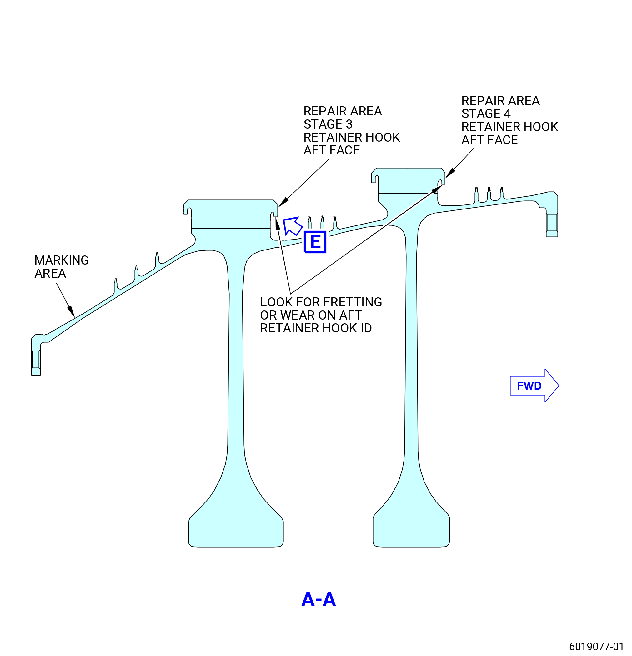
| C. | Do an inspection of the HPC stage 3-4 spool for repair marking and wear or fretting marking. Refer to Figure 1016 and as follows: |
| (1) | Do a visual inspection of the HPC stage 3-4 spool marking area to find, if the spool was previously repaired. |
| NOTE: |
|
| (2) | If the marking area found with the mark "R006-X" engraved on it, examine each dovetail aft retainer of the stage for “scallop repair” and put a mark "X" on the top of the dovetail slot outer surface where the scallop is found. Use an approved C05-003 marking pen or an equivalent. Refer to TASK 70-16-02-350-017 (TEMPORARY MARKING). |
| (3) | Check for fretting or wear marks on the aft retainer hook ID and put a mark "F" on the top of dovetail post, if it is not marked already. Use an approved C05-003 marking pen or an equivalent. Refer to TASK 70-16-02-350-017 (TEMPORARY MARKING). |
| (4) | If the 3-4 spool is neither repaired, nor wear, nor fretting marks are noticed, refer to Subtask 72-31-00-440-259 (paragraph 3.D.). |
| Subtask 72-31-00-440-259 |
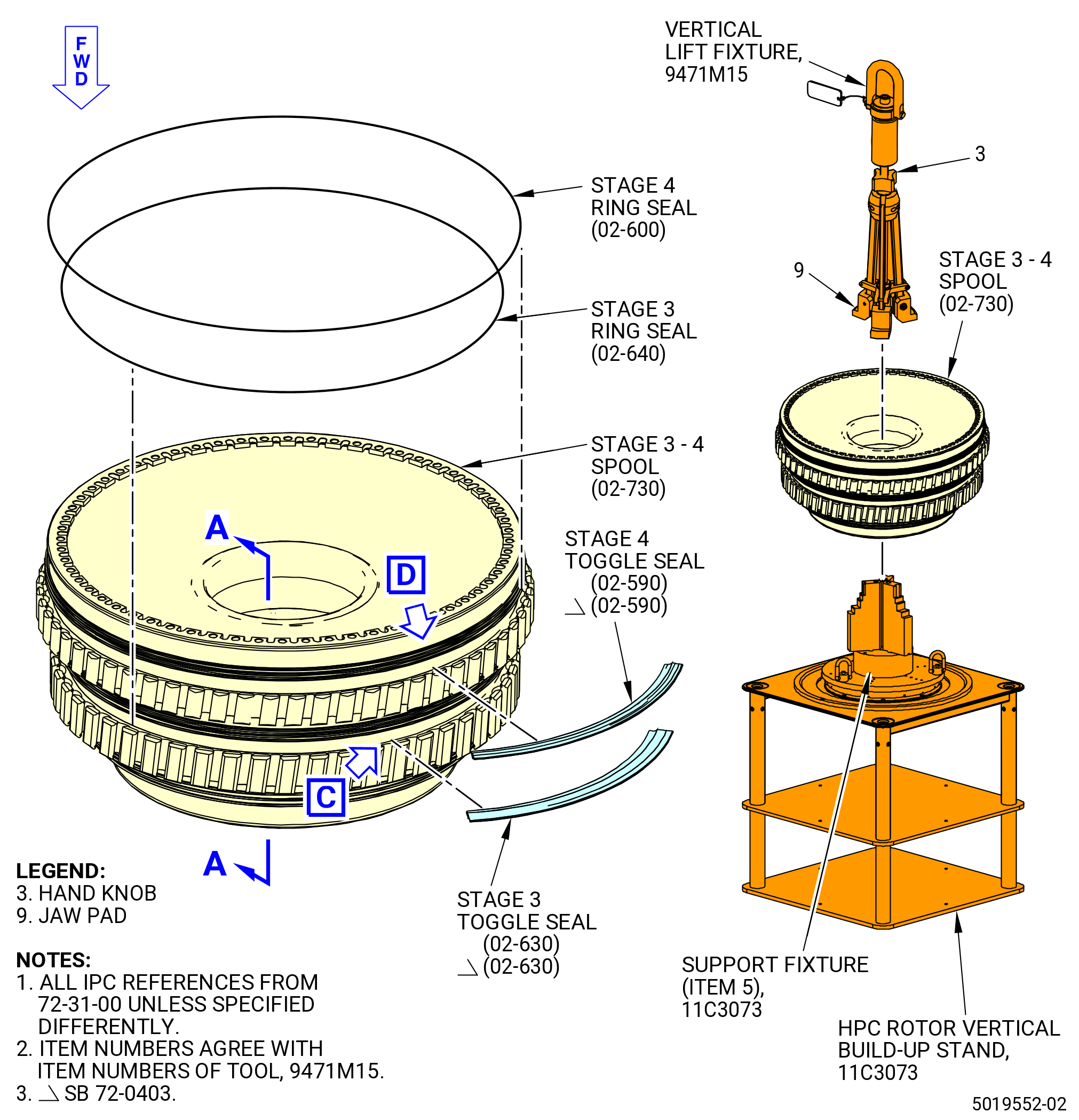
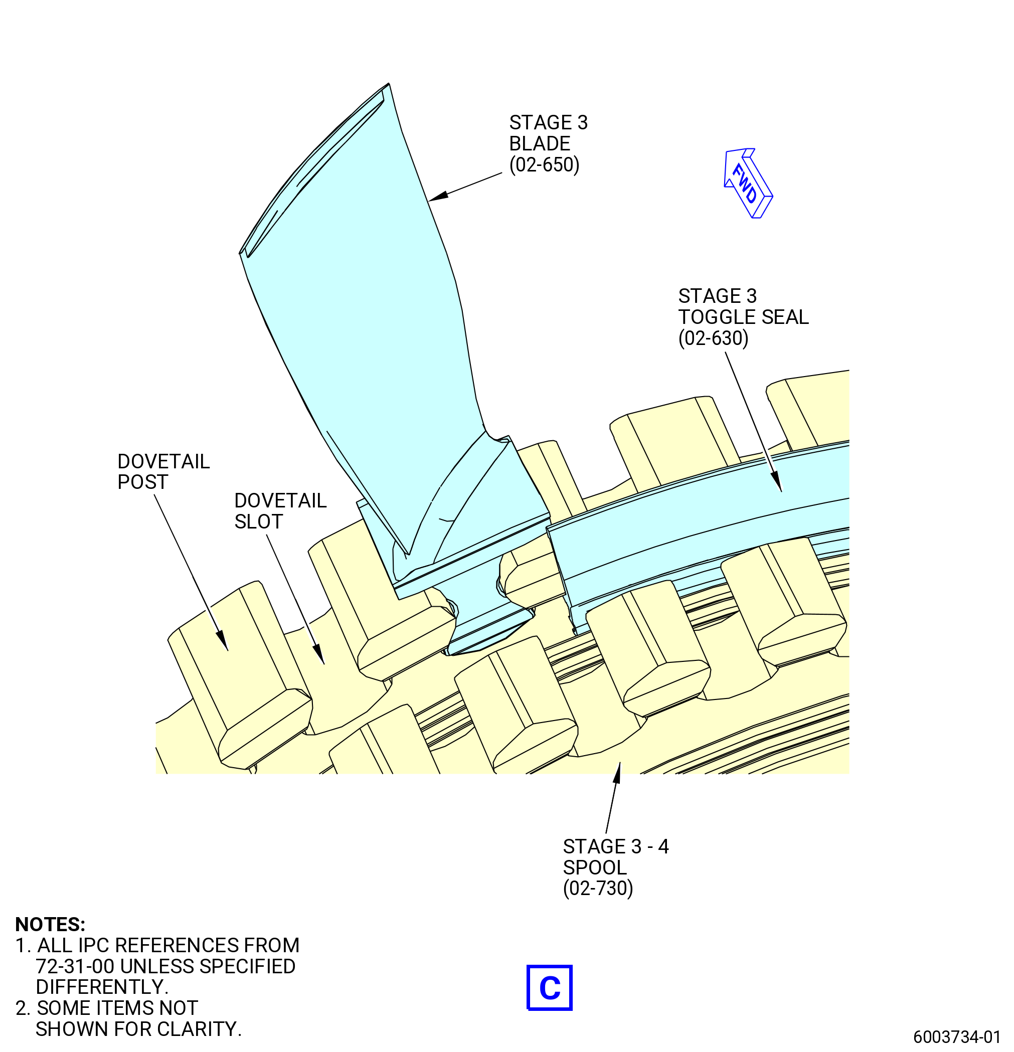
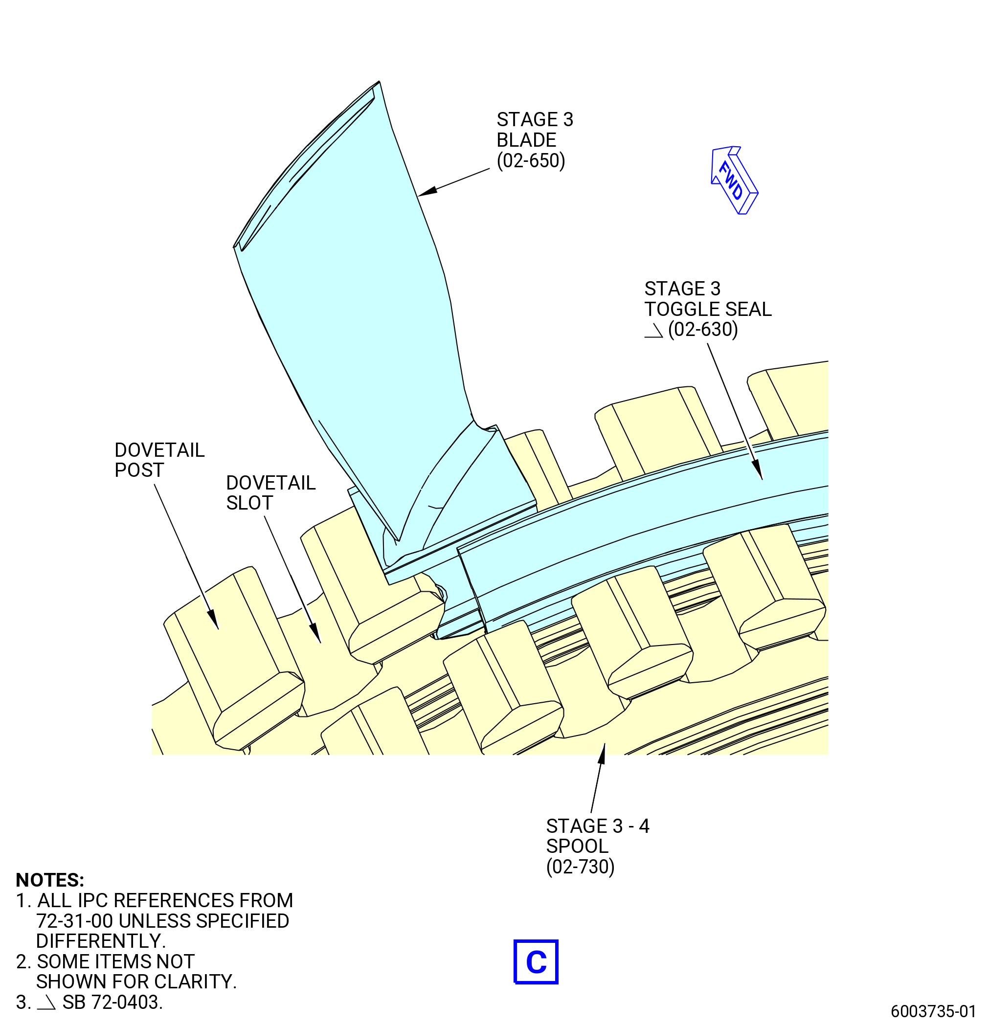
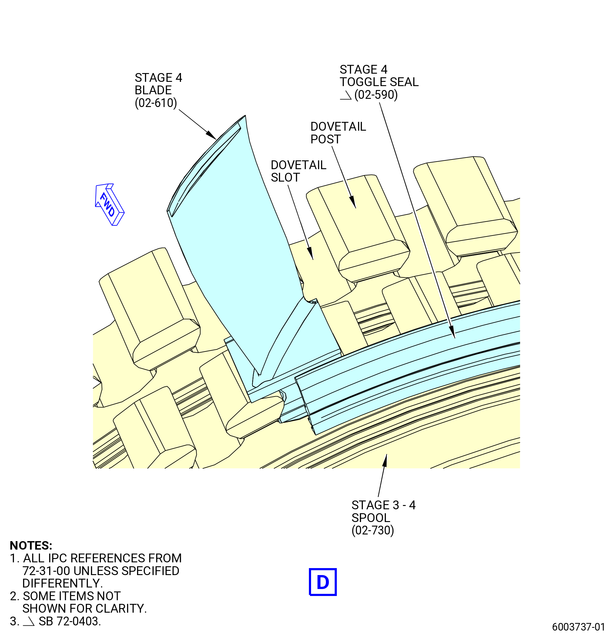
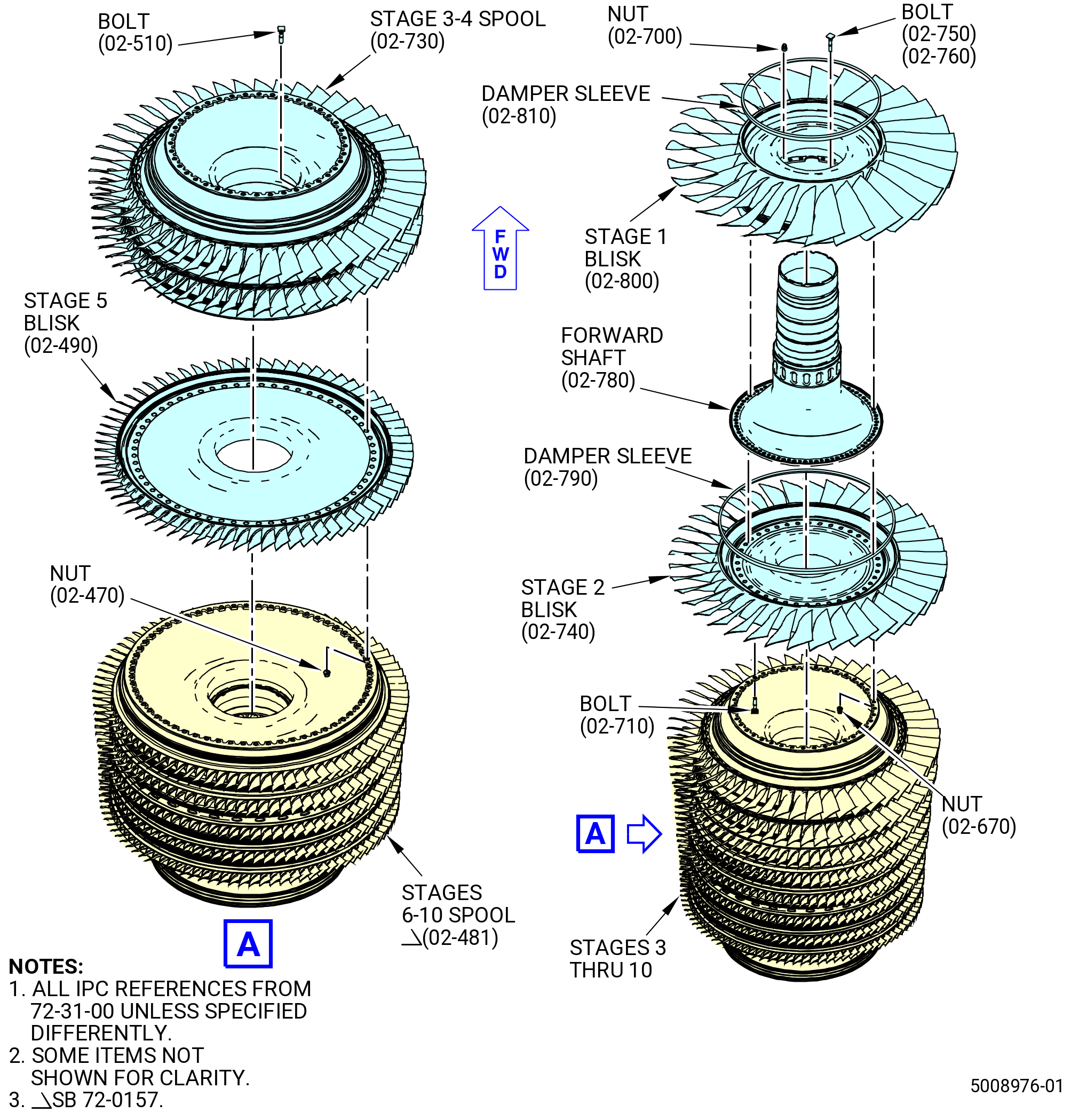
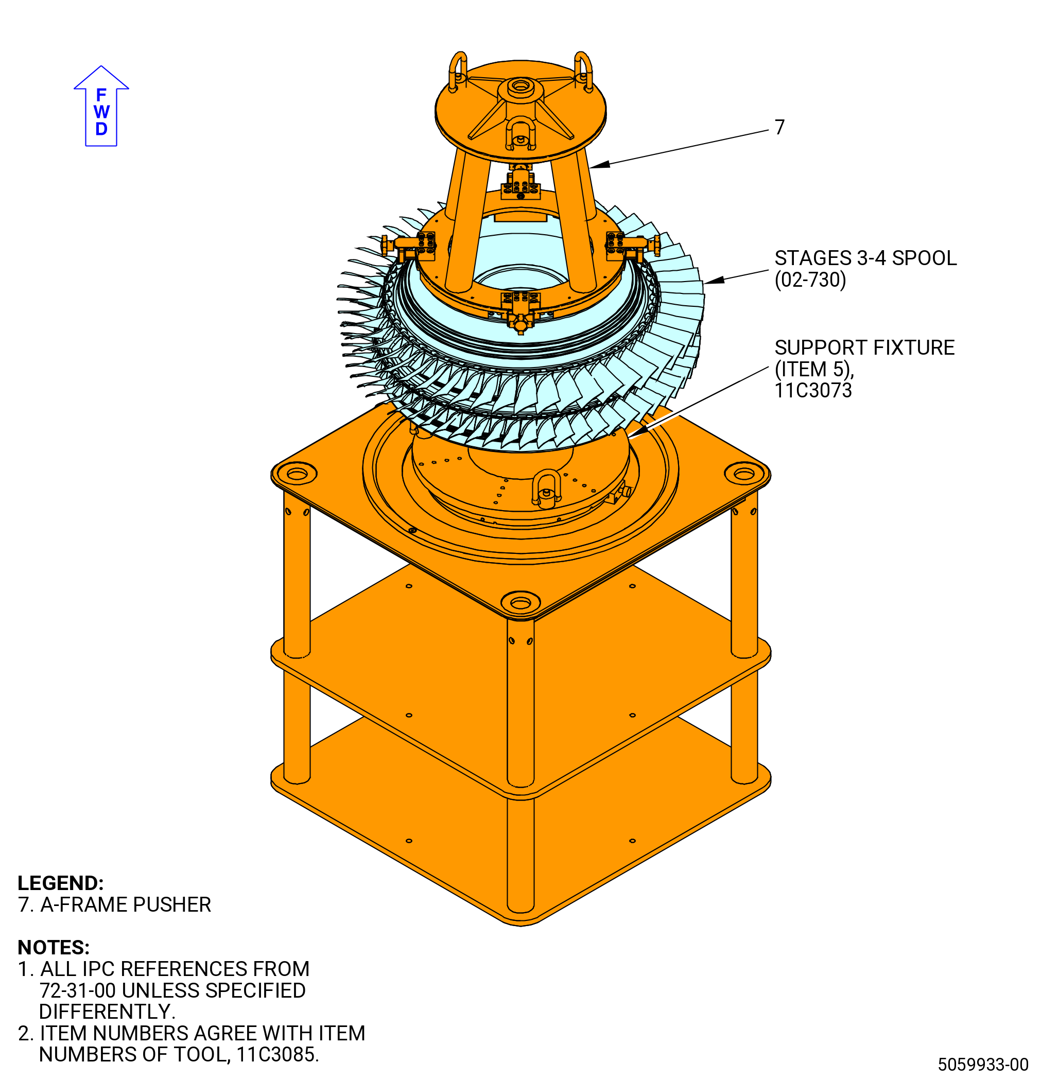
| D. | Install the stage 3 compressor rotor blades (stage 3 blades) (02-650) (SIN 057A3) and stage 4 compressor rotor blades (stage 4 blades) (02-610) (SIN 057A4) in the stage 3 and 4 compressor rotor spool (stages 3-4 spool) (02-730) (SIN 050B4). Refer to Figure 1016 and do as follows: |
| (1) | Put the stages 3-4 spool on the 11C3073 HPC rotor vertical build-up stand as follows: |
| (a) | Use the chuck wrench to compress the support fixture (item 5) until the stages 3-4 spool can be installed. |
| (b) | Attach a hoist to the 9471M15 vertical lift fixture. |
| (c) | Turn the hand knob (item 3) of the 9471M15 vertical lift fixture CCW to compress the three jaw pads (item 9). |
| (d) | Put the three jaw pads (item 9) in the aft bore of the stages 3-4 spool and on the stage 4 web. Turn the hand knob (item 3) CW to expand the jaw pads (item 9). |
| WARNING: |
|
| (e) | Lift the stages 3-4 spool and move it above the support fixture (item 5) of the 11C3073 HPC rotor vertical build-up stand. |
| (f) | Lower the stages 3-4 spool and put it on the support fixture (item 5) in the aft end up position. |
| (g) | Remove the 9471M15 vertical lift fixture from the stages 3-4 spool. Turn the hand knob (item 3) to compress the jaw pads (item 9). Move the 9471M15 vertical lift fixture up and away from the build-up stand. |
| CAUTION: |
|
| (h) | Use the chuck wrench to tighten the support fixture (item 5) of the 11C3073 HPC rotor vertical build-up stand sufficient to prevent radial movement of the stages 3-4 spool. |
| WARNING: |
|
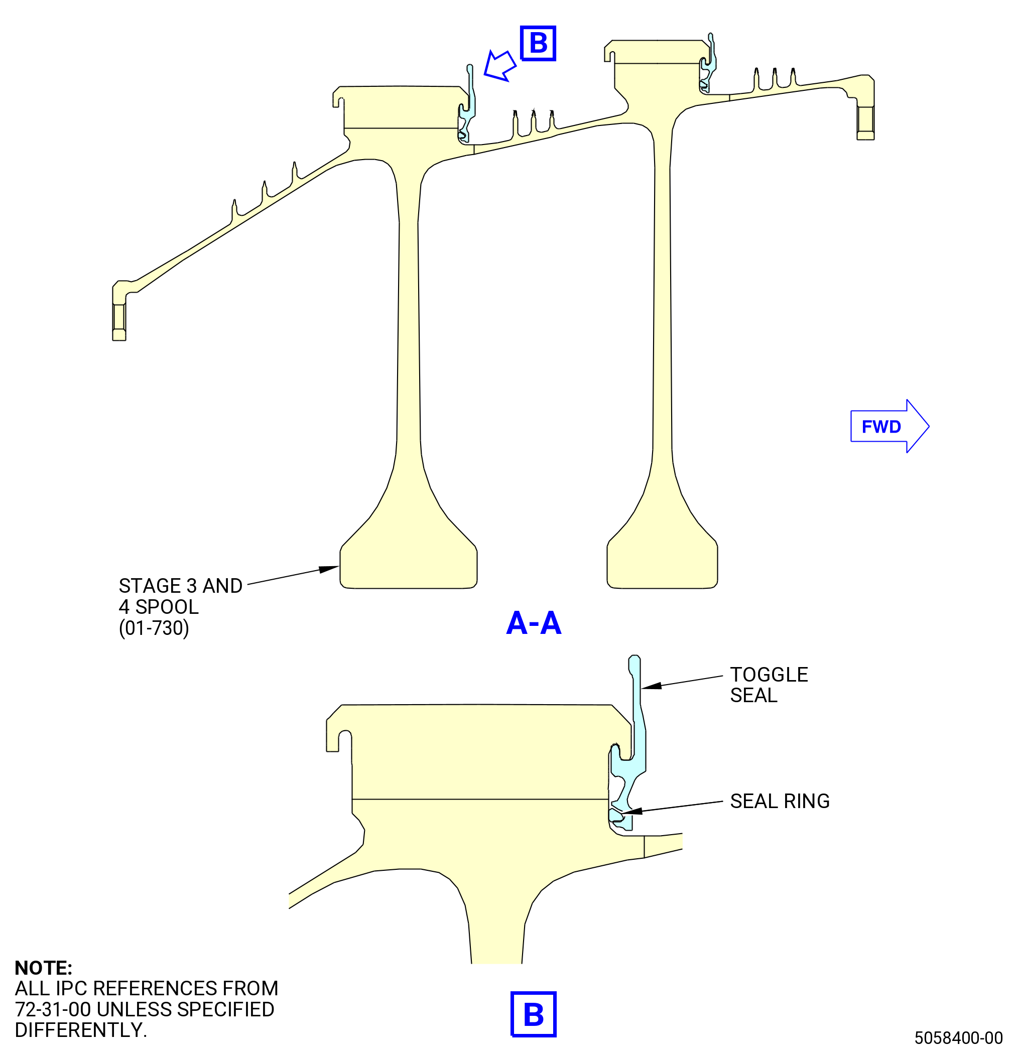
| (2) | Apply C02-033 petrolatum to the forward face of the seal (stage 3 toggle seal) (02-630) (SIN 050NA). |
| (3) | Apply C02-033 petrolatum to the forward face of the toggle seal (stage 4 toggle seal) (02-590) (SIN 050NB). |
| (4) | Install the ring seal (stage 3 ring seal) (02-640) (SIN 050P1) in the groove aft of the stage 3 dove tail posts. Expand the stage 3 ring seal sufficient to install it on the stages 3-4 spool. |
| (5) | Install the ring seal (stage 4 ring seal) (02-600) (SIN 050P2) in the groove aft of the stage 4 dovetail posts. Expand the stage 4 ring seal sufficient to install it on the stages 3-4 spool. |
| (6) | Install five stage 3 toggle seals (02-630) (SIN 050NA) on the stages 3-4 spool. Refer to Figure 1016 and do as follows: |
| Subtask 72-31-00-440-329 |
| * * * SB 72-0403( New Stage 3 and Stage 4 Toggle Seals Configuration ) |
| CAUTION: |
|
| (a) | If the spool is found with a temporary marking, refer to Subtask 72-31-00-440-328 (paragraph 3.C.), install the toggle seals in such a way that the repaired or worn aft retainer hook is positioned at the middle of the toggle seal segment. Refer to Figure 1016. |
| NOTE: |
|
| * * * END SB 72-0403 |
| Subtask 72-31-00-440-330 |
| (b) | Engage the groove of one of the stage 3 toggle seals with the stage 3 ring seal and put stage 3 toggle seal on the aft face of the dovetail posts. |
| Subtask 72-31-00-440-320 |
| * * * PRE SB 72-0403( Old Stage 3 and Stage 4 Toggle Seals Configuration ) |
| (c) | Make sure that the 11 hooks of the stage 3 toggle seal (02-630) (SIN 050NA) are between the stage 3 dovetail posts. Make sure that the ends of the stage 3 toggle seals (02-630) (SIN 050NA) are on the middle of a stage 3-4 spool (02-730) (SIN 050B4) post. |
| * * * END PRE SB 72-0403 |
| Subtask 72-31-00-440-321 |
| * * * SB 72-0403( New Stage 3 and Stage 4 Toggle Seals Configuration ) |
| (c).A. | Make sure that the 10 hooks of the stage 3 toggle seal (02-630) (SIN 050NA) are between the stage 3 dovetail posts. Make sure that the ends of the stage 3 toggle seals (02-630) (SIN 050NA) are on the middle of the dovetail slot. |
| * * * END SB 72-0403 |
| Subtask 72-31-00-440-322 |
| (d) | Install the remaining four stage 3 toggle seals on the stage 3 dovetail posts. |
| (e) | Move the stage 3 toggle seals in a circumferential direction to lock the hooks of the stage 3 toggle seals with the slots on the inboard side of the dovetail posts. |
| (7) | Install five stage 4 toggle seals (02-590) (SIN 050NB) on the stages 3-4 spool as follows: |
| Subtask 72-31-00-440-333 |
| * * * SB 72-0403( New Stage 3 and Stage 4 Toggle Seals Configuration ) |
| CAUTION: |
|
| (a) | If the spool is found with a temporary marking, refer to Subtask 72-31-00-440-328 (paragraph 3.C.), install the toggle seals in such a way that the repaired or worn aft retainer hook is positioned at the middle of the toggle seal segment. Refer to Figure 1016. |
| 1 | Deleted. |
| NOTE: |
|
| * * * END SB 72-0403 |
| Subtask 72-31-00-440-334 |
| (b) | Engage the groove of one of the stage 4 toggle seals with the stage 4 ring seal and put stage 4 toggle seal on the aft face of the dovetail posts. |
| Subtask 72-31-00-440-323 |
| * * * PRE SB 72-0403( Old Stage 3 and Stage 4 Toggle Seals Configuration ) |
| (c) | Make sure that the 13 hooks of the stage 4 toggle seal (02-590) (SIN 050NB) are between the stage 4 dovetail posts. Make sure that the ends of the stage 4 toggle seals (02-590) (SIN 050NB) are on the middle of a stage 3-4 spool (02-730) (SIN 050B4) post. |
| * * * END PRE SB 72-0403 |
| Subtask 72-31-00-440-324 |
| * * * SB 72-0403( New Stage 3 and Stage 4 Toggle Seals Configuration ) |
| (c).A. | Make sure that the 12 hooks of the stage 4 toggle seal (02-590) (SIN 050NB) are between the stage 4 dovetail posts. Make sure that the ends of the stage 4 toggle seals (02-590) (SIN 050NB) are on the middle of the dovetail slot. |
| * * * END SB 72-0403 |
| Subtask 72-31-00-440-319 |
| (d) | Install the remaining four stage 4 toggle seals on the stage 4 dovetail posts. |
| (e) | Move the stage 4 toggle seals in a circumferential direction to lock the hooks of the stage 4 toggle seals with the slots on the inboard side of the dovetail posts. |
|
|
|
|
| Subtask 72-31-00-220-046 |
| (8) | Do a visual inspection to make sure of a correct installation of the ring seals as follows: |
| (a) | Make sure that all the stage 3 toggle seal hooks are engaged in the grooves of the stage 3 dovetail posts. |
| (b) | Make sure that the stage 3 ring seal is correctly engaged in the groove of the stage 3 toggle seals. |
| (c) | Make sure that all the stage 4 toggle seal hooks are engaged in the grooves of the stage 4 dovetail posts. |
| (d) | Make sure that the stage 4 ring seal is correctly engaged in the groove of the stage 4 toggle seals. |
| Subtask 72-31-00-440-260 |
| (9) | Put a piece of C10-021 tape on one of the stage 3 toggle seals and across the dovetail posts to prevent movement of the toggle seals during assembly. |
| (10) | Put a piece of C10-021 tape on one of the stage 4 toggle seals and across the dovetail posts to prevent movement of the toggle seals during assembly. |
| Subtask 72-31-00-440-261 |
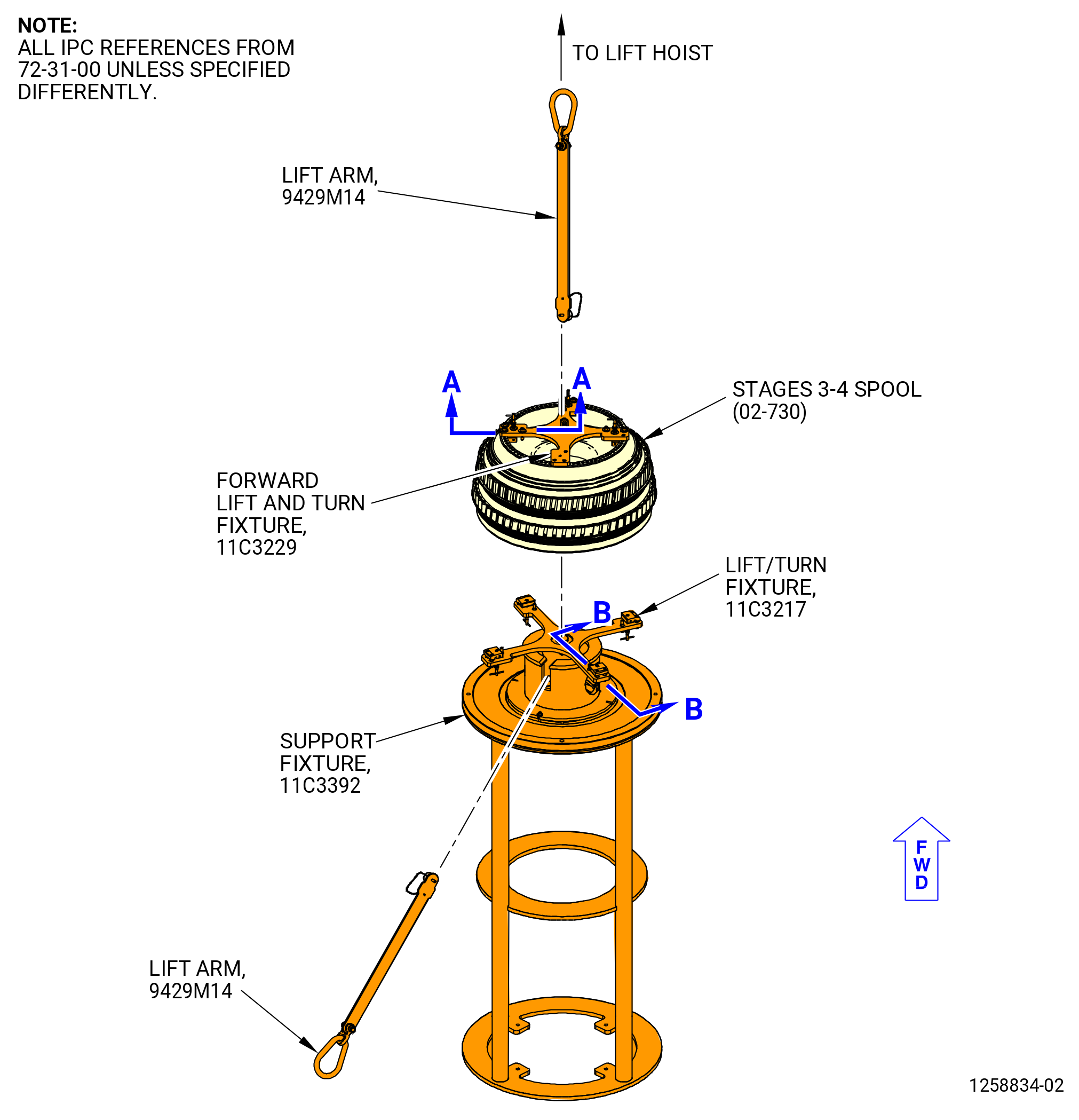
| (11) | Turn the stages 3-4 spool to the aft end down position. Refer to Figure 1017 and do as follows: |
| (a) | Make sure that the round (item 4), plate (item 5), plate (item 6), and capscrews (item 10) of the 11C3392 support fixture are installed on the support (item 2) of the 11C3392 support fixture. |
| (b) | Put the 11C3229 forward lift and turn fixture on the 11C3392 support fixture as follows: |
| 1 | Attach the 9429M14 lift arm to the 11C3229 forward lift and turn fixture with a ball lock pin (item 5) of the 9429M14 lift arm. |
| WARNING: |
|
| 2 | Put the 11C3229 forward lift and turn fixture on the round (item 4), plate (item 5), and plate (item 6) of the 11C3392 support fixture. |
| (c) | Install the 11C3217 lift/turn fixture on the aft flange of the stages 3-4 spool as follows: |
| 1 | Attach the 9429M14 lift arm to the 11C3217 lift/turn fixture with a ball lock pin (item 5) of the 9429M14 lift arm. |
| 2 | Loosen the eight captive screws (item 5) of the 11C3217 lift/turn fixture. |
| 3 | Push the pins (item 4) in and turn to move the clamps (item 3). |
| 4 | Align the boltholes of the 11C3229 forward lift and turn fixture with the boltholes on the aft flange of the stages 3-4 spool and put the 11C3229 forward lift and turn fixture on the aft flange. |
| 5 | Push the pins (item 4) in and turn them to put the clamps (item 3) above the aft face of the forward flange. |
| 6 | Tighten the eight captive screws (item 5). |
| (d) | Operate the hoist to put tension on the 9429M14 lift arm. |
| (e) | Use the chuck wrench to compress the support fixture (item 5) of the 11C3073 HPC rotor vertical build-up stand to remove the stages 3-4 spool. |
| (f) | Operate the hoist and move the stages 3-4 spool above the 11C3229 forward lift and turn fixture. |
| (g) | Align the boltholes of the stages 3-4 spool with boltholes of the 11C3229 forward lift and turn fixture and lower it on the 11C3229 forward lift and turn fixture. |
| (h) | Attach the 11C3229 forward lift and turn fixture to the forward flange of the stages 3-4 spool as follows: |
| 1 | Push the pins (item 4) in and turn them to put the clamps (item 3) above the aft face of the forward flange. |
| 2 | Tighten the eight captive screws (item 5). |
| WARNING: |
|
| (i) | Operate the hoist and lift the stages 3-4 spool from the 11C3392 support fixture. |
| (j) | Attach one more hoist to the 9429M14 lift arm that is attached to the 11C3229 forward lift and turn fixture. |
| (k) | Operate the hoists to lift the forward end and lower the aft end of the stages 3-4 spool. |
| (l) | Remove the 11C3217 lift/turn fixture. |
| (m) | Put the stages 3-4 spool on the 11C3073 HPC rotor vertical build-up stand as follows: |
| 1 | Lower the stages 3-4 spool and put it on the support fixture (item 5) of the 11C3073 HPC rotor vertical build-up stand. |
| 2 | Remove the 11C3229 forward lift and turn fixture from the stages 3-4 spool. |
| CAUTION: |
|
| 3 | Use the chuck wrench to tighten the support fixture (item 5) only sufficient to prevent radial movement of the stages 3-4 spool. |
| Subtask 72-31-00-440-262 |
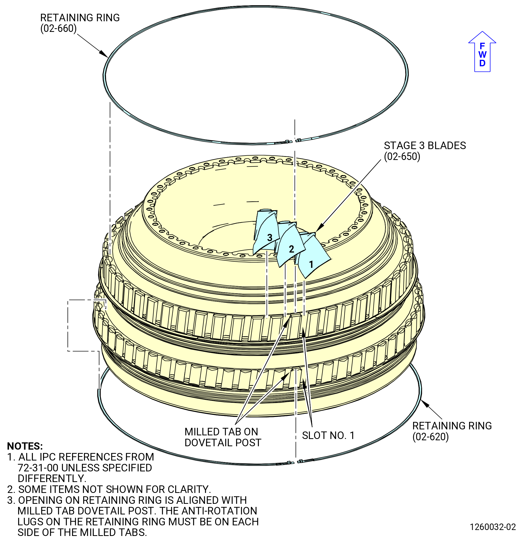
| (12) | Put marks of the dovetail post positions of stage 3 and stage 4. Refer to Figure 1018 and do as follows: |
| (a) | Find the milled tab on the stage 3 dovetail post. |
| NOTE: |
|
| (b) | Use the C05-003 marking pen to mark a number 1 on the dovetail post with the milled tab and on the first dovetail post CCW of it. Refer to TASK 70-16-02-350-017 (TEMPORARY MARKING). |
| (c) | Find the milled tab on the stage 4 dovetail post. |
| NOTE: |
|
| (d) | Use the C05-003 marking pen to mark a number 1 on the dovetail post with the milled tab and on the first dovetail post CCW of it. Refer to TASK 70-16-02-350-017 (TEMPORARY MARKING). |
| Subtask 72-31-00-440-263 |
| (13) | Find the mass weight and the installation sequence of the stage 3 blades (02-650) (SIN 057A3) as follows: |
| (a) | Use a digital scale to find the mass weight of each stage 3 blade. |
| (b) | Record the mass weight on each blade with a C05-003 marking pen. Refer to TASK 70-16-02-350-017 (TEMPORARY MARKING). |
| (c) | Put the blades in the sequence of their mass weight. Use the C05-003 marking pen to put a sequence number on each blade. Refer to TASK 70-16-02-350-017 (TEMPORARY MARKING). |
| (d) | Find the installation position for the stage 3 blades as follows: |
| 1 | Use the 9446M61 computer program and put the sequence number of each blade and its related mass weight in the computer. |
| 2 | Calculate the data with the computer and get the installation sequence. Print the computer installation sheet for the stage 3 blades (02-650) (SIN 057A3). |
| (e) | Remove the sequence number from each blade (one at a time) and identify the installation position of the blade with the C05-003 marking pen. Refer to TASK 70-16-02-350-017 (TEMPORARY MARKING). |
| Subtask 72-31-00-440-264 |
| (14) | Install the stage 3 blades. Refer to Figure 1018 and do as follows: |
| (a) | Remove the C10-021 tape from the stage 3 toggle seal and dovetail posts. |
| (b) | Use the computer installation sheet for the stage 3 blades and install the blades in the necessary sequence. |
| (c) | Begin at dovetail slot No. 1 and install the stage 3 blades CW FLA in the order specified on the computer installation sheet. Install the blades with the convex side facing up. |
| (d) | Install a retaining ring (02-660) (SIN 050W3) in the grooves on the inboard side of the stage 3 dovetail posts. |
| (e) | If necessary use a nylon bar to move the retaining ring so the opening is located on the dovetail post with the milled tab. Make sure that the ends of the retaining ring are seated in the milled tab and that the anti-rotation lugs on the ends of the retaining ring are on each side of the milled tab. |
| Subtask 72-31-00-440-265 |
| (15) | Find the mass weight and the installation sequence of the stage 4 blades (02-610) (SIN 057A4) as follows: |
| (a) | Use a digital scale to find the mass weight of each stage 4 blade. |
| (b) | Record the mass weight on each blade with a C05-003 marking pen. Refer to TASK 70-16-02-350-017 (TEMPORARY MARKING). |
| (c) | Put the blades in the sequence of their mass weight. Use a C05-003 marking pen to put a sequence number on each blade. Refer to TASK 70-16-02-350-017 (TEMPORARY MARKING). |
| (d) | Find the installation position for the stage 4 blades as follows: |
| 1 | Use the 9446M61 computer program and put the sequence number of each blade and its related mass weight in the computer. |
| 2 | Calculate the data with the computer and get the installation sequence. Print the computer installation sheet for the stage 4 of blades. |
| (e) | Remove the sequence number from each blade (one at a time) and identify the installation position of the blade with the C05-003 marking pen. Refer to TASK 70-16-02-350-017 (TEMPORARY MARKING). |
| Subtask 72-31-00-440-266 |
| (16) | Install the stage 4 blades (02-610) (SIN 057A4). Refer to Figure 1018 and do as follows: |
| (a) | Remove the C10-021 tape from the stage 4 toggle seal and dovetail posts. |
| (b) | Use the computer installation sheet for the stage 4 blades and install the blades in the necessary sequence. |
| (c) | Begin at dovetail slot No. 1 and install the stage 4 blades CW in the order specified on the computer installation sheet. Install the blades with the convex side facing up. |
| (d) | Install a retaining ring (02-620) (SIN 050W4) in the grooves on the inboard side of the stage 4 dovetail posts. |
| (e) | If necessary use a nylon bar to move the retaining ring so the opening is located on the dovetail post with the milled tab. Make sure that the ends of the retaining ring are seated in the milled tab and that the anti-rotation lugs on the ends of the retaining ring are on each side of the milled tab. |
| Subtask 72-31-00-440-267 |
| (17) | Put the two stage 3 covers (item 4) of the 11C3419 blade protector set on the stage 3 blades. Attach the covers together with the velcro fasteners. |
| (18) | Put the two stage 4 covers (item 5) on the stage 4 blades. Attach the covers together with the velcro fasteners. |
| Subtask 72-31-00-440-269 |
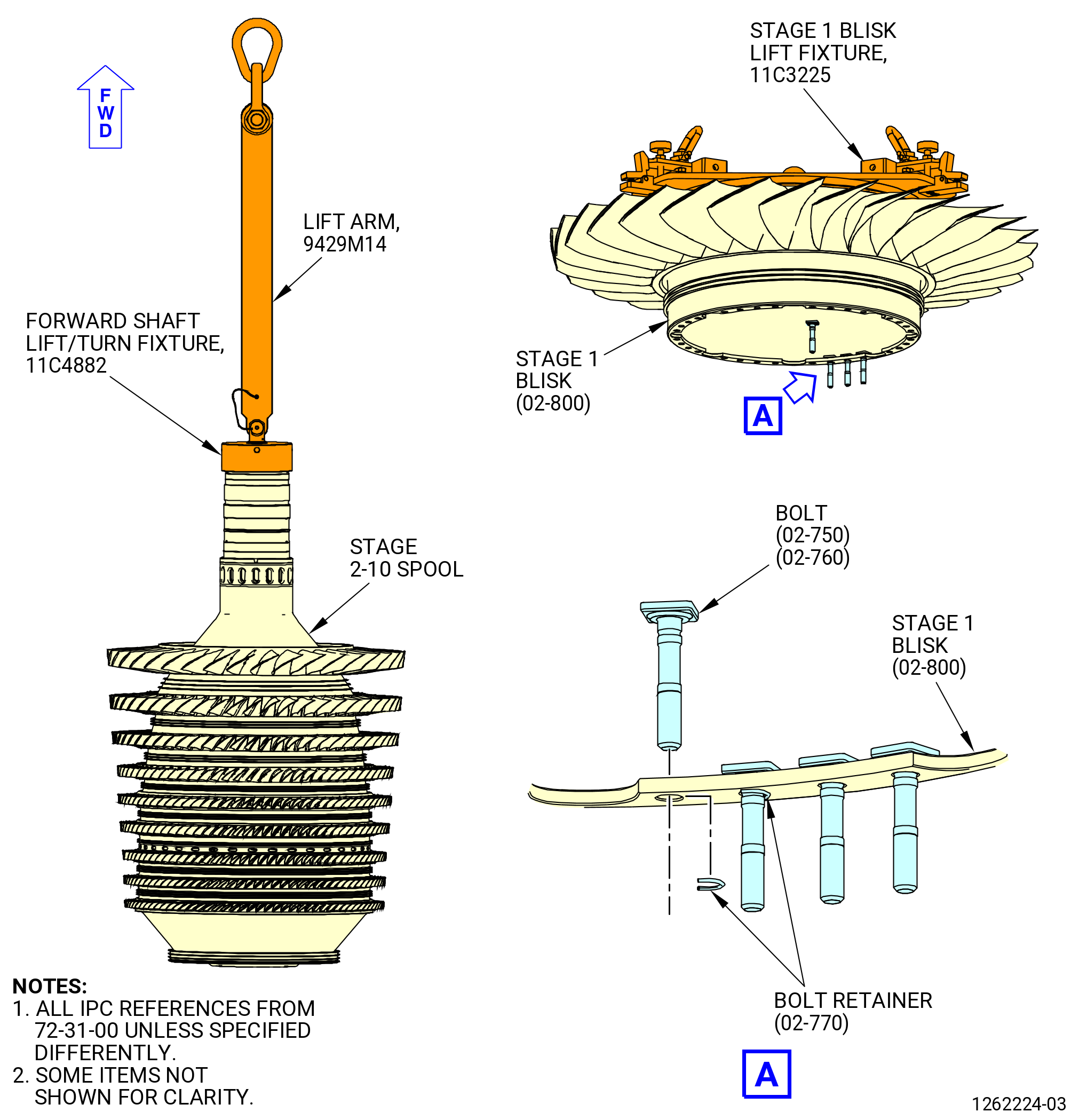
| E. | Install the square head bolts (bolts) (02-510) (SIN 050F0) and the bolt retainers (02-500) (SIN 050WH) in the stages 3-4 spool (02-730) (SIN 050B4). Refer to Figure 1021 and do as follows: |
| (1) | Install 60 bolts (02-510) (SIN 050F0) in the boltholes on the aft flange stages 3-4 spool. |
| (2) | Install the bolt retainers (02-500) (SIN 050WH) on the bolts. |
| Subtask 72-31-00-440-270 |
| F. | Alternative Procedure Available. High pressure compressor rotor stack procedure. |
| (1) | Find the predicted stack for the installation of the CDP seal (02-460) (SIN 050NC) as follows: |
| (a) | Find the stack projection value that is marked on the aft outer face of the stages 6-10 spool (02-481) (SIN 050AR). Refer to Figure 1019. |
| NOTE: |
|
| (b) | Record the stack projection value for the stages 6-10 spool into the 9471M13 inspection system. |
| (c) | Find the stack projection value that is marked on the aft face of the CDP seal. |
| NOTE: |
|
| (d) | Record the stack projection value for the CDP seal into the 9471M13 inspection system. |
| (e) | Get a computer printout of the predicted stack for the CDP seal. Keep the computer printout with the CDP seal. |
| NOTE: |
|
| Subtask 72-31-00-440-271 |
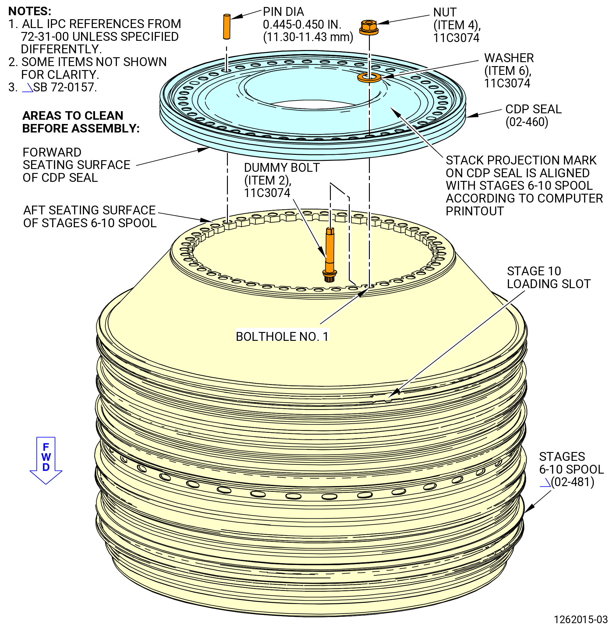
| (2) | Install the CDP seal (02-460) (SIN 050NC) on the stages 6-10 spool (02-481) (SIN 050AR). Refer to Figure 1019 and do as follows: |
| (a) | Install the two halves of the stage 6 cover (item 7) of the 11C3419 blades protector set above the stage 6 blades. Attach the two halves of the 11C3419 blades protector set together with the velcro fasteners. |
| (b) | Install the two halves of the stage 7 cover (item 8) above the stage 7 blades. Attach the two halves of the 11C3419 blades protector set together with the velcro fasteners. |
| (c) | Install the two halves of each of the stage 8 thru 10 covers (item 9) above the stage 8 trhu stage 10 blades. Attach the two halves of each of the 11C3419 blades protector set together with the velcro fasteners. |
| (d) | Install the stages 6-10 spool on the 11C3073 HPC rotor vertical build-up stand as follows: |
| 1 | Use the chuck wrench to compress the support fixture (item 5) until the stages 6-10 spool can be installed. |
| 2 | Attach a hoist to the 9471M15 vertical lift fixture. |
| 3 | Turn the hand knob (item 3) of the 9471M15 vertical lift fixture CCW to compress the three jaw pads (item 9). |
| 4 | Put the three jaw pads (item 9) in the bore of the stages 6-10 spool and on the stage 10 web. Turn the hand knob (item 3) CW to expand the jaw pads (item 9). |
| WARNING: |
|
| 5 | Lift the stages 6-10 spool and move it above the support fixture (item 5) of the 11C3073 HPC rotor vertical build-up stand. |
| 6 | Lower the stages 6-10 spool and put it on the support fixture (item 5) in the forward end down position. |
| 7 | Remove the 9471M15 vertical lift fixture from the stages 6-10 spool. |
| CAUTION: |
|
| 8 | Use the chuck wrench to tighten the support fixture (item 5) of the 11C3073 HPC rotor vertical build-up stand only sufficient to prevent radial movement of the stages 6-10 spool. |
| Subtask 72-31-00-160-019 |
| (e) | Install the CDP seal (02-460) (SIN 050NC) as follows: |
| WARNING: |
|
| 1 | Use C04-035 isopropyl alcohol, C04-002 Stoddard solvent, or a 50-50 blend of C04-035 isopropyl alcohol and C04-228 denatured alcohol to clean the aft seating surface of the stages 6-10 spool and the forward seating surface of the CDP seal. Refer to Figure 1019. |
| Subtask 72-31-00-440-272 |
| 2 | Put the CDP seal on the stages 6-10 spool as follows: |
| a | Attach a hoist to the 9471M15 vertical lift fixture. |
| b | Turn the hand knob (item 3) of the 9471M15 vertical lift fixture CCW to compress the three jaws pads (item 9). |
| c | Put the three jaw pads (item 9) in the aft bore of the CDP seal. Turn the hand knob (item 3) CW to expand the law pads (item 9). |
| WARNING: |
|
| d | Operate the hoist to lift the CDP seal and move it above the aft flange of the stages 6-10 spool. |
| e | Align the SP mark on the CDP seal to agree with the SP mark on the stages 6-10 spool at the stack orientation angle that is shown on the computer printout. Refer to Figure 1019. |
| Subtask 72-31-00-440-273 |
| (g) | Alternative Procedure Available. Attach the CDP seal (02-460) (SIN 050NC) to the stages 6-10 spool as follows: |
| 1 | Locate the No. 1 bolthole for the CDP seal. Refer to Figure 1019. |
| NOTE: |
|
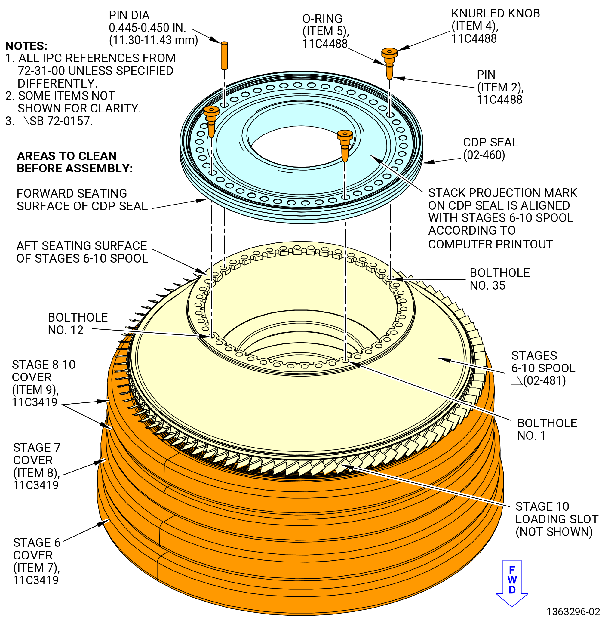
| 2 | Use four dummy bolts (item 2), washer (item 6), and nuts (item 4) of the 11C3074 dummy bolt tool kit and install the boltheads forward into the stages 6-10 spool/CDP seal flange at four equally-spaced locations at boltholes No. 1, 11, 23, and 35. |
| 3 | Do not torque the nuts (item 4), at this time. |
| 4 | Use a 0.445-0.450 inch (11.30-11.43 mm) diameter pin in one of the open boltholes to make sure that the boltholes are aligned. |
| WARNING: |
|
| CAUTION: |
|
| 5 | Heat the CDP seal to 190-210°F (88-99°C). |
| 6 | Make sure the CDP seal is properly seated when the 0.445-0.450 inch (11.30-11.43 mm) diameter pin can fully enter all of the open boltholes. |
| 7 | Slowly torque the eight nuts (item 4) to 240 lb in. (27.1 Nm) in a criss-cross pattern. |
| 8 | Let the temperature of the CDP seal decrease to ambient temperature. |
| 9 | Install the remaining dummy bolts (item 2) and nuts (item 4) in every other bolthole, for a total of 23 dummy bolts (item 2). |
| 10 | Torque all 23 nuts (item 4) to 100 lb in. (11.3 Nm) in a criss-cross pattern. |
| 11 | Torque all 23 nuts (item 4) to 300 lb in. (33.9 Nm) in a criss-cross pattern. |
| Subtask 72-31-00-440-274 |
| (g).A. | Alternative Procedure. Attach the CDP seal (02-460) (SIN 050NC) to the stages 6-10 spool (02-481) (SIN 050AR). Refer to Figure 1020 and do as follows: |
| 1 | Locate the No. 1 bolthole for the CDP seal. |
| NOTE: |
|
| WARNING: |
|
| 2 | Apply a light coating of C02-019 lubricant or C02-023 engine oil on the O-ring (item 5) of the 11C4488 alignment pin. |
| 3 | Install the O-ring (item 5) in the groove of each of three pins (item 2). |
| 4 | Install three pins (item 2) from aft to forward into the stages 6-10 spool and CDP seal flange at the boltholes No. 1, 12, and 35. |
| 5 | Make sure that the pins (item 2) are fully inserted and that the bottom of the knurled knobs (item 4) are in contact with the CDP seal. |
| 6 | Use a 0.445-0.450 inch (11.30-11.43 mm) diameter pin in one of the open boltholes to make sure that the boltholes are aligned. |
| WARNING: |
|
| CAUTION: |
|
| 7 | Use a propane torch in a circular motion and increase the temperature of the CDP seal until it is properly seated on the stages 6-10 spool. The CDP seal is properly seated when the 0.445-0.450 inch (11.30-11.43 mm) diameter pin can fully go into all of the open boltholes. |
| 8 | Let the temperature of the CDP seal decrease to ambient temperature. |
| 9 | Install 22 dummy bolts (item 2), washers (item 6), and nuts (item 4) of the 11C3074 dummy bolt tool kit in every other bolthole. Start from bolthole No. 2. |
| NOTE: |
|
| 10 | Pull and twist the knurled knobs (item 4) to remove the three pins (item 2) of the 11C4488 alignment pin. |
| 11 | Install the remaining dummy bolt (item 2), washer (item 6), and nut (item 4) in the bolthole No. 12, for a total of 23 dummy bolts. |
| 12 | Torque all 23 nuts (item 4) to 100 lb in. (11.3 Nm) in a criss-cross pattern. |
| Subtask 72-31-00-220-047 |
| (3) | Do a check of the CDP seal (02-460) (SIN 050NC) to stages 6-10 spool (02-481) (SIN 050AR) as follows: |
| (a) | Install the 11C3106 aft end lift/turn fixture or the 11C3060 lift/turn fixture on the aft flange of the CDP seal. Refer to Subtask 72-31-00-420-026 (paragraph 3.A.(16)) or Subtask 72-31-00-420-027 (paragraph 3.A.(16)A.) . |
| (b) | Install the 11C3217 lift/turn fixture on the forward flange of the stages 6-10 spool as follows: |
| 1 | Install the round (item 4), plates (item 5 and 6), and capscrews (item 10) of the 11C3392 support fixture on the support (item 2). |
| 2 | Attach the 9429M14 lift arm to the 11C3392 lift/turn fixture with a ball lock pin (item 5) of the 9429M14 lift arm. |
| 3 | Put the 11C3217 lift/turn fixture on the round (item 4), plates (item 5 and 6) of the 11C3392 support fixture. |
| 4 | Loosen the eight captive screws (item 5) of the 11C3217 lift/turn fixture. |
| 5 | Push the pins (item 4) in and turn to move the clamps (item 3). |
| 6 | Use the chuck wrench to compress the support fixture (item 5) of the 11C3073 HPC rotor vertical build-up stand until the CDP seal can be removed from the stages 6-10 spool assembly. |
| WARNING: |
|
| 7 | Operate the hoist to lift the CDP seal to stages 6-10 spool assembly and move it above the 11C3217 lift/turn fixture. Lower the CDP seal to stages 6-10 spool assembly on the forward lift fixture. |
| 8 | Attach the 11C3217 lift/turn fixture to the forward flange of the stages 6-10 spool as follows: |
| a | Push the pins (item 4) in and turn them to put the clamps (item 3) above the aft face of the forward flange. |
| b | Tighten the eight captive screws (item 5). |
| WARNING: |
|
| (c) | Operate the hoist and lift the CDP seal to stages 6-10 spool assembly. |
| (d) | Attach one more hoist to the 9429M14 lift arm that is attached to the 11C3217 lift/turn fixture. |
| WARNING: |
|
| (e) | Operate the hoist to lift the forward end and lower the aft end of the stages 6-10 spool. |
| (f) | Remove the 11C3106 aft end lift/turn fixture or the 11C3060 lift/turn fixture. |
| (g) | Install the CDP seal to the stages 6-10 spool assembly on the 9471M13 inspection system as follows: |
| 1 | Use the chuck wrench to compress the three jaw chuck (item 4) of the 11C3009 compressor rotor support fixture to let the installation of the CDP seal to stages 6-10 spool assembly. |
| 2 | Operate the hoist and lower the CDP seal to the stages 6-10 spool assembly on the three jaw chuck (item 4) in the aft end down position. |
| 3 | Use the chuck wrench to tighten the three jaw chuck (item 4) sufficient to prevent radial movement of the CDP seal to stages 6-10 spool assembly. |
| 4 | Remove the 11C3217 lift/turn fixture from the stages 6-10 spool. |
| (h) | Do a check of the CDP seal to stages 6-10 spool assembly. Refer to the 9471M13 inspection system manufacterer's instructions. |
| (i) | If the check is satisfactory, get the computer printout of the SP value for the CDP to stages 6-10 spool assembly. |
| (j) | If the check is not satisfactory, speak to your GEAE representative. |
| Subtask 72-31-00-440-275 |
| (4) | Find the predicted stack for the installation of the stages 3-4 spool (02-730) (SIN 050B4) and the stage 5 blisk (02-490) (SIN 056A5) on the stages 6-10 spool (02-481) (SIN 050AR) as follows: |
| (a) | Find the stack projection value from the computer printout for the CDP seal and stages 6-10 spool assembly. Refer to Subtask 72-31-00-220-047 (paragraph 3.G.(9)). |
| (b) | Record the stack projection value for the CDP seal and stages 6-10 spool assembly into the 9471M13 inspection system. |
| (c) | Find the stack projection value that is marked on the forward face of the stage 5 blisk. |
| NOTE: |
|
| (d) | Record the stack projection value for the stage 5 blisk into the 9471M13 inspection system. |
| (e) | Find the stack projection value that is marked on the forward outer face of the stages 3-4 spool. |
| NOTE: |
|
| (f) | Record the stack projection value for the stages 3-4 spool into the 9471M13 inspection system. |
| (g) | Get a computer printout of the predicted stack for the stage 5 blisk and the stages 3-4 spool. |
| NOTE: |
|
| Subtask 72-31-00-440-276 |
| (5) | Install the stage 5 blisk (02-490) (SIN 056A5) and the stages 3-4 spool (02-730) (SIN 050B4) on the stages 6-10 spool (02-481) (SIN 050AR). Refer to Figure 1021 and do as follows: |
| (a) | Install the stages 6-10 spool on the 11C3072 vertical support adapter as follows: |
| 1 | Install the 11C3217 lift/turn fixture on the forward flange of the stages 6-10 spool as follows: |
| a | Attach the 9429M14 lift arm to the 11C3217 lift/turn fixture with a ball lock pin (item 5) of the 9429M14 lift arm. |
| b | Loosen the eight captive screws (item 5) of the 11C3217 lift/turn fixture. |
| c | Push the pins (item 4) in and turn to move the clamps (item 3). |
| WARNING: |
|
| d | Operate the hoist and put the 11C3217 lift/turn fixture on the forward flange of the stages 6-10 spool. |
| e | Push the pins (item 4) in and turn to move the clamps (item 3) above the aft face of the forward flange. |
| f | Tighten the eight captive screws (item 5). |
| g | Operate the hoist and put tension on the 11C3217 lift/turn fixture. |
| Subtask 72-31-00-160-020 |
| WARNING: |
|
| 2 | Use C04-035 isopropyl alcohol to clean stages 6-10 aft side. |
| Subtask 72-31-00-440-277 |
| 3 | Use the chuck wrench to compress the three jaw chuck (item 4) of the of the 11C3009 compressor rotor support fixture until the stages 6-10 spool can be removed. |
| WARNING: |
|
| 4 | Operate the hoist and put the stages 6-10 spool on the 11C3072 vertical support adapter. |
| 5 | Remove the 11C3217 lift/turn fixture from the forward flange of the stages 6-10 spool. |
| 6 | Install the support puller arm (item 42) of the 11C3085 clamp fixture as follows: |
| a | Put the support puller arm (item 42) through the center of the stages 6-10 spool and engage the threads of the support puller arm (item 42) with the hydraulic cylinder (item 11). |
| b | Hand tighten the support puller arm (item 42). |
| (b) | Prepare the stages 3-4 spool for installation as follows: |
| Subtask 72-31-00-160-021 |
| WARNING: |
|
| 1 | Use C04-035 isopropyl alcohol to clean stages 3-4 aft side. |
| Subtask 72-31-00-440-278 |
| 2 | Install the 9471M15 vertical lift fixture on the stages 3-4 spool. |
| a | Attach a hoist to the 9471M15 vertical lift fixture. |
| b | Turn the hand knob (item 3) CCW to compress the three jaw pads (item 9) of the 9471M15 vertical lift fixture. |
| c | Put the three jaw pads (item 9) in the forward bore of the stages 3-4 spool and on the stages 3 web. Turn the hand knob (item 3) CW to expand the paw pads (item 9). |
| WARNING: |
|
| 3 | Operate the hoist and lift the stages 3-4 spool above a clean work surface. |
| Subtask 72-31-00-160-022 |
| WARNING: |
|
| 4 | Use C04-035 isopropyl alcohol, C04-002 Stoddard solvent, or a 50-50 blend of C04-035 isopropyl alcohol and C04-228 denatured alcohol to clean the forward and aft seating surfaces of the stages 3-4 spool. |
| Subtask 72-31-00-440-279 |
| (e) | Alternative Procedure Available. Install the stage 5 blisk (02-490) (SIN 056A5) on the stages 6-10 spool (02-481) (SIN 050AR). Refer to Figure 1021, Figure 1022 and do as follows: |
| 1 | Prepare the 9481M70 heat fixture for use as follows: |
| NOTE: |
|
| WARNING: |
|
| a | Make sure the 9446M18 controller power switch is in the OFF position. |
| b | Connect the junction box (item 41) and flanged male connector (item 40C) on the 9481M70 heat fixture to the controller's receptacle. |
| c | Make sure that both bayonet mount thermocouples (item 40) of the 9481M70 heat fixture are in the vertical position. |
| d | Put the insulation blanket (item 17) on the tray (item 42). |
| NOTE: |
|
| e | Turn the 9446M18 controller power switch is in the ON position. |
| f | Push the controller's reset timer button to activate the timer. Refer to the Controller's Operating Instructions. |
| WARNING: |
|
| CAUTION: |
|
| g | Set the gear/hardware temperature of the 9446M18 controller to 425°F (218°C). |
| NOTE: |
|
| h | Remove the insulation blanket (item 17) from the tray (item 42). |
| 2 | Install the 9471M15 vertical lift fixture on the stage 5 blisk as follows: |
| a | Attach one more hoist to the 9471M15 vertical lift fixture. |
| b | Turn the hand knob (item 3) CCW to compress the three jaw pads (item 9). |
| c | Put the three jaw pads (item 9) in the forward bore of the stage 5 blisk. |
| d | Turn the hand knob (item 3) CW to expand the jaw pads (item 9). |
| WARNING: |
|
| 3 | Operate the hoist and put the stage 5 blisk on the 9481M70 heat fixture. Refer to Figure 1022. |
| 4 | Make sure that the bayonet mount thermocouple (item 40) is in contact with the hardware to get correct temperature readings. |
| 5 | Put the insulation blanket (item 17) on the 9481M70 heat fixture to cover the stage 5 blisk and the tray (item 42) to prevent heat loss. |
| 6 | Press the button of the controller reset timer to activate timer circuit. Refer to the Controller's Operating Instructions. |
| WARNING: |
|
| CAUTION: |
|
| 7 | Set the temperature of the controller gear/hardware to 425°F (218°C). |
| 8 | Check the temperature indicated by the digital readout on the 9446M18 controller. Double check the temperature with a manual or infrared temperature sensor. |
| NOTE: |
|
| 9 | When the stage 5 blisk is at the correct temperature, remove the insulation blanket (item 17) from the tray (item 42) of the 9481M70 heat fixture. |
| WARNING: |
|
| 10 | Put two 11C3233 alignment pins in the boltholes of the stage 5 blisk. |
| 11 | Align the SP mark on the stage 5 blisk to agree with the SP mark on the stages 6-10 spool at the stack orientation angle that is shown on the computer printout. |
| 12 | Operate the hoist and lower the stage 5 blisk on the forward flange of the stages 6-10 spool. |
| 13 | Remove the two 11C3233 alignment pins from the stage 5 blisk. |
| 14 | Remove the 9471M15 vertical lift fixture from the stage 5 blisk. |
| Subtask 72-31-00-440-280 |
| (e).A. | Alternative Procedure. Install the stage 5 blisk on the stages 6-10 spool. Refer to Figure 1021 and do as follows: |
| 1 | Put the stage 5 covers (item 6) of the 11C3419 blade protector set on the blades of the stage 5 blisk. |
| 2 | Install one more hoist to the 9471M15 vertical lift fixture on the stage 5 blisk as follows: |
| a | Attach one more hoist to the 9471M15 vertical lift fixture. |
| b | Turn the hand knob (item 3) CCW to compress the three jaw pads (item 9). |
| c | Put the three jaw pads (item 9) in the forward bore of the stage 5 blisk. Turn the hand knob (item 3) CW to expand the jaw pads (item 9). |
| WARNING: |
|
| 3 | Operate the hoist and put the stage 5 blisk above the stages 6-10 spool. |
| WARNING: |
|
| CAUTION: |
|
| 4 | Use a propane torch to increase the temperature of the stage 5 blisk to a maximum of 425°F (218°C). Makse sure to continually move the torch around the stage 5 blisk and do not create any located hot spots. |
| 5 | Put two 11C3233 alignment pins in the boltholes of the stage 5 blisk. |
| 6 | Align the SP mark on the stage 5 blisk to agree with the SP mark on the stages 6-10 spool at the stack orientation angle that is shown on the computer printout. |
| WARNING: |
|
| 7 | Operate the hoist and lower the stage 5 blisk on the forward flange of the stages 6-10 spool. |
| 8 | Remove the two 11C3233 alignment pins from the stage 5 blisk. |
| 9 | Remove the 9471M15 vertical lift fixture from the stage 5 blisk. |
| Subtask 72-31-00-440-281 |
| (f) | Install the stages 3-4 spool on the stage 5 blisk and stages 6-10 spool. Refer to Figure 1021 and as follows: |
| WARNING: |
|
| 1 | Operate the hoist and move the stages 3-4 spool above the stage 5 blisk. |
| WARNING: |
|
| CAUTION: |
|
| 2 | Use a propane torch to momentarily increase the temperature of the stage 5 blisk. Make sure to continually move the torch and do not create any located hot spots, |
| 3 | Align the SP mark on the stages 3-4 spool to agree with the SP mark on the stages 6-10 spool at the stack orientation angle that is shown on the computer printout. |
| 4 | Align the bolts in the aft flange of the stages 3-4 spool with the boltholes of the stage 5 blisk and stages 6-10 spool and operate the hoist to lower the stages 3-4 spool an on the stage 5 blisk. |
| 5 | Remove the 9471M15 vertical lift fixture from the stages 3-4 spool. |
| Subtask 72-31-00-440-282 |
| (g) | Install the 11C3085 clamp fixture on the forward flange of the stages 3-4 spool. Refer to Figure 1023 and do as follows: |
| WARNING: |
|
| 1 | Put the middle puller arm (item 43) through the stages 3-4 spool and engage the threads of the middle puller arm (item 43) with the threads of the support puller arm (item 42). Hand tighten the middle puller arm (item 43). |
| 2 | Install the A-frame pusher (item 7) on the forward flange of the stages 3-4 spool. |
| 3 | Put the locking rod (item 9) through the A-frame pusher (item 7) and engage the threads of the locking rod (item 9) with the threads of the middle arm puller (item 43). Make sure that the parts and tooling are centered. Hand tighten the locking rod (item 9). |
| WARNING: |
|
| CAUTION: |
|
| 4 | Use the hydraulic hand pump (item 13) to apply 3000-5000 psi (20684-34474 kPa). |
| 5 | Let the temperature of the stage 5 blisk decrease to ambient temperature. |
| 6 | Release the hydraulic pressure and remove the 11C3085 clamp fixture. |
| Subtask 72-31-00-440-283 |
| (h) | Attach the stages 3-4 spool to the stage 5 blisk and stages 6-10 spool. Refer to Figure 1021 and do as follows: |
| WARNING: |
|
| 1 | Apply C02-058 lubricant to the threads and friction surfaces of 60 self-locking nuts (nuts) (02-470) (SIN 050K0). |
| 2 | Install the 11C4481 torque fixture on the forward flange of the stages 3-4 spool. Refer to the torque fixture manufacturer's instructions. |
| 3 | Put the 60 nuts (02-470) (SIN 050K0) on the 60 bolts (02-510) (SIN 050F0). |
| 4 | Torque the 60 nuts to 202-238 lb in. (22.8-26.9 Nm) in a criss-cross pattern. Refer to the torque fixture manufacterer's instructions. |
| 5 | Remove the 11C4481 torque fixture from the forward flange of the stages 3-4 spool. |
| Subtask 72-31-00-220-048 |
| (6) | Do a check of the CDP seal (02-460) (SIN 050NC) through the stages 3-4 spool (02-730) (SIN 050B4) assembly as follows: |
| (a) | Install the 9471M15 vertical lift fixture on the CDP seal through the stages 3-4 spool assembly as follows: |
| 1 | Attach a hoist to the 9471M15 vertical lift fixture. |
| 2 | Turn the hand knob (item 3) CCW to compress the three jaw pads (item 9). |
| 3 | Put the three jaw pads (item 9) in the bore of the stages 3-4 spool and on the stage 3 web. Turn the hand knob (item 3) CW to expand the jaw pads (item 9). |
| WARNING: |
|
| 4 | Operate the hoist and lift the CDP seal through stages 3-4 spool assembly from the 11C3072 vertical support adapter. |
| (b) | Install the CDP seal through stages 6-10 spool assembly on the 9471M13 inspection system as follows: |
| 1 | Use the chuck wrench to compress the three jaw chuck (item 4) of the 11C3009 compressor rotor support fixture to let the installation of the CDP seal through stages 3-4 spool assembly. |
| 2 | Operate the hoist to lower the CDP seal through stages 3-4 spool assembly on the three jaw chuck (item 4) in the aft end down position. |
| 3 | Use the chuck wrench to tighten the three jaw chuck (item 4) sufficient to prevent radial movement of the CDP seal through stages 3-4 spool assembly. |
| 4 | Remove the 9471M15 vertical lift fixture from the stages 3-4 spool. |
| (c) | Do an inspection of the CDP rotating seal through the stages 3-4 spool assembly. Refer to the 9471M13 inspection system manufacterer's instructions. |
| 1 | Maximum limit for runout is 0.002 inch (0.05 mm). |
| 2 | Maximum limit for concentricity is 0.002 inch (0.05 mm). |
| 3 | If the inspection is satisfactory, get the computer printout of the SP value for the CDP rotating seal through stage 3-4 spool assembly. |
| 4 | If the inspection is not satisfactory, speak to your GEAE representative. |
| Subtask 72-31-00-440-284 |
| (7) | Find the predicted stack for the installation of the stage 2 blisk (02-740) (SIN 056A2) and the forward shaft (02-780) (SIN 050B5) on the CDP seal through stages 3-4 spool assembly as follows: |
| (a) | Find the stack projection value from the computer printout for the CDP seal through stages 3-4 spool assembly. Refer to Subtask 72-31-00-220-048 (paragraph 3.J.(4)). |
| (b) | Record the stack projection value from the computer printout for the CDP seal through stage 3-4 spool assembly into the 9471M13 inspection system. |
| (c) | Find the stack projection value that is marked on the forward face of the stage 2 blisk. |
| NOTE: |
|
| (d) | Record the stack projection value for the stage 2 blisk into the 9471M13 inspection system. |
| (e) | Find the stack projection value that is marked on the aft outer face of the forward shaft. |
| NOTE: |
|
| (f) | Record the stack projection value for the forward shaft into the 9471M13 inspection system. |
| (g) | Get a computer printout of the predicted stack for the stage 2 blisk and the forward shaft. |
| NOTE: |
|
| Subtask 72-31-00-440-285 |
| (8) | Install the CDP seal through stages 3-4 spool assembly on the 11C3072 vertical support adapter as follows: |
| (a) | Install the 9471M15 vertical lift fixture on the CDP seal through stages 3-4 spool assembly as follows: |
| WARNING: |
|
| 1 | Attach a hoist to the 9471M15 vertical lift fixture. |
| 2 | Turn the hand knob (item 3) CCW to compress the three jaw pads (item 9). |
| 3 | Put the three jaw pads (item 9) in the bore of the stages 3-4 spool and on the stage 3 web. Turn the hand knob (item 3) CW to expand the jaw pads (item 9). |
| 4 | Operate the hoist to put tension on the 9471M15 vertical lift fixture. |
| (b) | Use the chuck wrench to compress the three jaw chuck (item 4) of the 11C3009 compressor rotor support fixture until the CDP seal can be removed through stages 3-4 spool assembly. |
| (c) | Operate the hoist and put the CDP seal through stages 3-4 spool assembly on the 11C3072 vertical support adapter. |
| (d) | Remove the 9471M15 vertical lift fixture. |
| Subtask 72-31-00-440-286 |
| (9) | Install the square head bolt (bolt) (02-710) (SIN 050F5) in the forward flange of the stages 3-4 spool. Refer to Figure 1021 and do as follows: |
| (a) | Find the H mark on the stage 1 blisk (02-800) (SIN 056A1) aft outer surface approximately 1.0 inch (25 mm) from the aft seating flange. |
| NOTE: |
|
| (b) | Find the H mark on the forward face of the stage 2 blisk (02-740) (SIN 056A2). |
| NOTE: |
|
| (c) | Put the stage 1 blisk in position with the H mark on the aft outer surface 180 degrees from the H mark on the stage 2 blik. |
| (d) | Find the eight scallops on the aft face on the stage 1 blisk. |
| (e) | Copy the eight scallop positions of the stage 1 blisk to the forward face of the stage 2 blisk. Mark the copied positions on the forward face of the stage 2 blisk with a C05-003 marking pen. Refer to TASK 70-16-02-350-017 (TEMPORARY MARKING). |
| (f) | Align the SP mark on the stage 2 blisk to agree with the SP mark on the stages 3-4 spool at the stack orientation angle that is shown on the computer printout. Refer to Subtask 72-31-00-440-284 (paragraph 3.K.(7)). |
| (g) | Copy the eight scallop positions that were marked on the forward face of the stage 2 blisk to the forward face of the stages 3-4 spool. Mark the copied positions on the forward face of the stages 3-4 spool with a C05-003 marking pen. Refer to TASK 70-16-02-350-017 (TEMPORARY MARKING). |
| (h) | Install eight bolts (02-710) (SIN 050F5) in the forward flange of the stages 3-4 spool at the positions that were marked. |
| (i) | Install a bolt retainer (02-720) (SIN 050WV) on each of the eight bolts. |
| Subtask 72-31-00-440-287 |
| (10) | Install the stage 2 blisk (02-740) (SIN 056A2) and the forward shaft (02-780) (SIN 050B5) on the stages 3-4 spool (02-730) (SIN 050B4). Refer to Figure 1021 and do as follows: |
| WARNING: |
|
| (a) | Apply C02-058 lubricant to the threads and friction surfaces of eight self-locking nuts (nut) (02-700) (SIN 050K5). |
| (b) | Put the 11C3224 chill fixture on a clean work surface. Refer to Figure 1024. |
| WARNING: |
|
| (c) | Fill the 11C3224 chill fixture with dry ice. |
| (d) | Install the 11C4882 forward shaft lift/turn fixture on the forward shaft as follows: |
| 1 | Attach the hoist to the 9429M14 lift arm. |
| 2 | Attach the 9429M14 lift arm to the 11C4882 forward shaft lift/turn fixture with a ball-lock pin (item 5) on the 9429M14 lift arm. |
| 3 | Engage the threads of the 11C4882 forward shaft lift/turn fixture with the threads on the forward shaft. Hand-tighten the 9429M14 lift arm. |
| Subtask 72-31-00-160-023 |
| WARNING: |
|
| (e) | Use C04-035 isopropyl alcohol, C04-002 Stoddard solvent, or a 50-50 blend of C04-035 isopropyl alcohol and C04-228 denatured alcohol to clean the aft seating surface of the forward shaft. |
| Subtask 72-31-00-440-288 |
| WARNING: |
|
| WARNING: |
|
| (f) | Operate the hoist and put the aft end of the forward shaft in the 11C3224 chill fixture for 30 minutes to decrease the temperature. Refer to Figure 1024. |
| (g) | Put the stage 2 covers (item 3) of the 11C3419 blade protector set around stage 2 blades. Attach the covers (item 3) together with the velcro fasteners. |
| (h) | Install the 9471M15 vertical lift fixture on the stage 2 blisk as follows: |
| 1 | Attach one more hoist to the 9471M15 vertical lift fixture. |
| 2 | Turn the hand knob (item 3) CCW to compress the three jaw pads (item 9). |
| 3 | Put the three jaw pads (item 9) in the bore of the stage 1 blisk. Turn the hand knob (item 3) CW to expand the jaw pads (item 9). |
| Subtask 72-31-00-160-024 |
| WARNING: |
|
| (i) | Use C04-035 isopropyl Alcohol, C04-002 Stoddard solvent, or a 50-50 blend of C04-035 isopropyl alcohol and C04-228 denatured alcohol to clean the forward and aft seating surfaces of the stage 2 blisk. |
| Subtask 72-31-00-440-289 |
| WARNING: |
|
| (j) | Operate the hoist and move the stage 2 blisk above the stages 3-4 spool. Refer to Figure 1021. |
| (k) | Align the SP mark on the stage 2 blisk to agree with the SP mark on the stages 3-4 spool at the stack orientation angle that is shown on the computer printout. Refer to Subtask 72-31-00-440-284 (paragraph 3.K.(7)). |
| WARNING: |
|
| CAUTION: |
|
| (l) | Use a propane torch to increase the temperature of the stage 2 blisk up to a maximum of 425°F (218°C). |
| (m) | Operate the hoist and put the stage 2 blisk on the stages 3-4 spool. |
| (n) | Install eight 5/16-24 inch free running nuts and spacers on the bolts (02-710) (SIN 050F5) to seat the shaft. Tighten the free running nuts in a criss-cross pattern. |
| (o) | Remove the 9471M15 vertical lift fixture from the stage 2 blisk. |
| (p) | Remove the eight 5/16-24 inch free running nuts and spacers. |
| WARNING: |
|
| (q) | Operate the hoist and move the forward shaft above the stage 2 blisk. |
| (r) | Align the SP mark on the forward shaft to agree with the SP mark on the stages 3-4 spool at the stack orientation angle that is shown on the computer printout. Refer to Subtask 72-31-00-440-284 (paragraph 3.K.(7)). |
| WARNING: |
|
| (s) | Operate the hoist and put the forward shaft on the stage 2 blisk. Make sure that there is no tension on the hoist. |
| (t) | Attach the forward shaft and the stage 2 blisk to the stages 3-4 spool with the eight nuts (02-700) (SIN 050K5). |
| NOTE: |
|
| (u) | Torque the nuts to 202 to 238 lb in. (22.8 to 26.9 Nm) in a criss-cross pattern. |
| (v) | Let the temperature of the parts to decrease to ambient temperature. |
| (w) | Break the torque on the nuts and then torque them again to 202-238 lb in. (22.8-26.9 Nm) in a criss-cross pattern. |
| (x) | Install the damper sleeve (02-790) (SIN 056B2) on the stage 2 blisk. |
| Subtask 72-31-00-220-049 |
| (11) | Do a final assembly measurement and a final assembly perpendicularity check as follows: |
| (a) | Install the CDP seal through forward shaft assembly on the 9471M13 inspection system as follows: |
| 1 | Use the chuck wrench to compress the three jaw chuck (item 4) of the 11C3009 compressor rotor support fixture to let the installation of the CDP seal through forward shaft. |
| WARNING: |
|
| 2 | Operate the hoist and move the CDP seal through the forward shaft above the three jaw chuck (item 4). |
| 3 | Operate the hoist and lower the CDP seal through the forward shaft on the three jaw chuck (item 4) in the aft end down position. |
| 4 | Use the chuck wrench to tighten the three jaw chuck (item 4) to prevent radial movement of the CDP seal through the forward shaft. |
| 5 | Remove the 11C4882 forward shaft lift/turn fixture from the forward shaft. |
| (b) | Do an inspection of the final assembly and the perpendicularity. Refer to the 9471M13 inspection system manufacturer's instructions: |
| 1 | Maximum limit for runout is 0.002 inch (0.05 mm). |
| 2 | Maximum limit for concentricity is 0.002 inch (0.05 mm). |
| 3 | If the inspection is satisfactory, get the computer printout of the inspection. |
| 4 | If the inspection is not satisfactory, speak to your GEAE representative. |
| Subtask 72-31-00-440-290 |
| (12) | Install the stage 1 blisk on the forward shaft. Refer to Figure 1025 and do as follows: |
| (a) | Put the stage 1 covers (item 2) of the 11C3419 blade protector set around the stage 1 blades. Attach the covers together with the velcro fasteners. |
| (b) | Install the 11C4882 forward shaft lift/turn fixture on the forward shaft as follows: |
| 1 | Attach a hoist to the 9429M14 lift arm. |
| NOTE: |
|
| WARNING: |
|
| 2 | Operate the hoist and move the 11C4882 forward shaft lift/turn fixture above the forward shaft. |
| 3 | Engage the threads of the 11C4882 forward shaft lift/turn fixture with the threads on the forward shaft. Hand-tighten the 9429M14 lift arm. |
| (c) | Put the CDP seal through the forward shaft assembly on the 11C3072 vertical support adapter as follows: |
| 1 | Use the chuck wrench to compress the three jaw chuck (item 4) of the 11C3009 compressor rotor support fixture until the CDP seal can be removed through stages 3-4 spool assembly. |
| WARNING: |
|
| 2 | Operate the hoist and put the CDP seal through the forward shaft assembly on the 11C3072 vertical support adapter. |
| 3 | Remove the 11C4882 forward shaft lift/turn fixture from the forward shaft. |
| (d) | Install the 11C3225 stage 1 blisk lift fixture on the forward face of the stage 1 blisk (02-800) (SIN 056A1) as follows: |
| 1 | Attach a hoist to a three-legged sling. |
| 2 | Attach the three-legged sling to each of the hoist rings (item 9). |
| 3 | Turn the knurled knobs (item 8) CCW to let the fingers (item 4) to pivot and lock in the groove of the clamps (item 5). |
| WARNING: |
|
| 4 | Operate the hoist and put the 11C3225 stage 1 blisk lift fixture on the forward face of the stage 1 blisk. |
| 5 | Move the clamps (item 5) radially out while turning the knurled knobs (item 8) CW to put the fingers (item 4) on the forward inner lip of the blades on the stage 1 blisk. |
| Subtask 72-31-00-160-025 |
| WARNING: |
|
| (e) | Use C04-035 isopropyl alcohol, C04-002 Stoddard solvent, or a 50-50 blend of C04-035 isopropyl alcohol and C04-228 denatured alcohol to clean the aft seating surface of the stage 1 blisk and the forward seating surface of the forward shaft. Refer to Figure 1026. |
| Subtask 72-31-00-440-291 |
| WARNING: |
|
| (f) | Operate the hoist and put the stage 1 blisk above a clean work surface. Do not lower the stage 1 blisk. |
| (g) | While the stage 1 blisk is suspended above the clean work surface, install square head bolts (bolts) (02-750) (SIN 050F1) and bolts (02-760) (SIN 050F2) in the aft flange of the stage 1 blisk. Refer to Figure 1025. |
| (h) | Bolts (02-760) (SIN 050F2) give approximately 28 gram-inches of balance correction. Add bolts (02-760) (SIN 050F2) as necessary to decrease the calculated vector sum of the stage 1 and stage 2 unbalance to less than 14 gram-inches. |
| (i) | Install a bolt retainer (02-770) (SIN 050WT) on each of the bolts. |
| (j) | Put the 11C3224 chill fixture on the clean work surface below the stage 1 blisk. Refer to Figure 1026. |
| WARNING: |
|
| (k) | Fill the chill fixture with dry ice. |
| CAUTION: |
|
| (l) | Operate the hoist and put the aft flange of the stage 1 blisk in the chill fixture for 20 minutes to decrease the temperature. |
| (m) | Put the 11C3436 forward shaft protector and the 11C3384 forward shaft protector on the forward shaft. Refer to Figure 1026. |
| WARNING: |
|
| (n) | Operate the hoist and move the stage 1 blisk above the forward shaft. |
| (o) | Find the H mark on the stage 1 blisk (02-800) (SIN 056A1) aft outer surface approximately 1.0 inch (25 mm) from the aft seating flange. |
| NOTE: |
|
| (p) | Find the H mark on the forward face of the stage 2 blisk (02-740) (SIN 056A2). |
| NOTE: |
|
| (q) | Put the stage 1 blisk in position with the H mark on the aft outer surface 180 degrees from the H mark on the stage 2 blisk. |
| (r) | Make sure that the bolts in the stage 1 blisk aft flange are aligned with the boltholes in the forward shaft. Make sure that the scallops on the aft face of the stage 1 blisk are aligned with the bolts installed in the stage 2 blisk and forward shaft. |
| (s) | Operate the hoist and lower the stage 1 blisk on the forward shaft. make sure that the bolts (02-750) (SIN 050F1) and (02-760) (SIN 050F2) are aligned with the boltholes of the forward shaft as the stage 1 blisk makes contact. |
| (t) | Remove the 11C3225 stage 1 blisk fixture fomr the stage 1 blisk. |
| (u) | Install the 11C3085 clamp fixture on the forward flange of the stage 1 blisk. Refer to Figure 1023 and do as follows: |
| 1 | Install the support puller arm (item 42) as follows: |
| a | Put the support puller arm (item 42) through the center of the forward shaft and engage the threads of the support puller arm with the hydraulic cylinder (item 11). |
| b | Hand tighten the support puller arm (item 42). |
| 2 | Put the middle puller arm (item 43) through the center of the forward shaft and engage the threads of the middle puller arm (item 43) with the threads of the support puller arm (item 42). Hand tighten the middle puller arm (item 43). |
| 3 | Put the upper puller arm (item 44) through the center of the forward shaft and engage the threads of the upper puller arm (item 44) with the threads of the middle puller arm (item 43). Hand tighten the middle puller arm (item 43). |
| 4 | Install the A-frame pusher (item 7) on the forward outer flange of the stage 1 blisk. |
| 5 | Put the locking rod (item 9) through the A-frame pusher (item 7) and engage the threads of the locking rod (item 9) with the threads of the upper puller arm (item 44). Make sure that the parts and tooling are centered. Hand tighten the locking rod (item 9). |
| WARNING: |
|
| CAUTION: |
|
| 6 | Use the hydraulic hand pump (item 13) to apply 2000 psi (13790 kPa). |
| 7 | Let the temperature of the stage 1 blisk decrease to ambient temperature. |
| 8 | Release the hydraulic pressure and remove the 11C3085 clamp fixture. |
| (v) | Attach the stage 1 blisk to the stage 2 blisk and forward shaft. Refer to Figure 1021 and do as follows: |
| WARNING: |
|
| 1 | Apply C02-058 lubricant to the threads and friction surfaces of 32 self-locking nuts (nut) (02-670) (SIN 050K2). |
| 2 | Install the 11C4481 torque fixture on the forward flange of the stage 1 blisk. Refer to the torque fixture manufacterer's instructions. |
| 3 | Put the 32 nuts (02-670) (SIN 050K2) down through the bore of the forward shaft and on the threads of the bolts (02-750) (SIN 050F1) and (02-760) (SIN 050F2). |
| 4 | Torque the 32 nuts to 202-238 lb in. (22.8-26-9 Nm) in a criss-cross pattern. Refer to the torque fixture manufacterer's instructions. |
| 5 | Remove the 11C4481 torque fixture from the forward flange of the stage 1 blisk. |
| 6 | Install the damper sleeve (02-810) (SIN 056B1) on stage 1 blisk. |
| (w) | Remove the 11C3436 forward shaft protector and the 11C3384 forward shaft protector from the forward shaft. |
| Subtask 72-31-00-220-050 |
| (13) | Do a check of the final assembly, final perpendicularity check, and 3R journal concentricity check of the HPC rotor assembly (15-012 , 72-30-00) (SIN 05000) as follows: |
| (a) | Install the 11C4882 forward shaft lift/turn fixture on the forward shaft (02-780) (SIN 050B5) and do as follows: |
| 1 | Attach a hoist to the 9429M14 lift arm. |
| 2 | Attach the 9429M14 lift arm to the 11C4882 forward shaft lift/turn fixture with a ball-lock pin (item 5) of the 9429M14 lift arm. |
| 3 | Engage the threads of the 11C4882 forward shaft lift/turn fixture with the threads on the forward shaft. Hand-tighten the 9429M14 lift arm. |
| (b) | Install the HPC rotor assembly on the 9471M13 inspection system as follows: |
| 1 | Use the chuck wrench to compress the three jaw chuck (item 4) of the 11C3009 compressor rotor support fixture to let the installation of the HPC rotor assembly. |
| WARNING: |
|
| 2 | Operate the hoist and move the HPC rotor assembly above the three jaw chuck (item 4), then lower the HPC rotor assembly in the aft end down position. |
| 3 | Use the chuck wrench to tighten the three jaw chuck (item 4) sufficient to prevent radial movement of the HPC rotor assembly. |
| 4 | Remove the 11C4882 forward shaft lift/turn fixture from the forward shaft. |
| (c) | Do an inspection of the final assembly, the final perpendicularity, and the 3R journal concentricity. Refer to the 9471M13 inspection system manufacterer's instructions: |
| 1 | Maximum limit for concentricity is 0.0025 inch (0.064 mm). Record the concentricity and the concentricity angle. |
| 2 | Maximum limit for perpendicularity is 0.002 inch (0.05 mm). Record the perpendicularity and the perpendicularity angle. |
| 3 | If the inspection is satisfactory, get the computer printout of the inspection. |
| 4 | If the inspection is not satisfactory, speak to your GEAE representative. |
| (d) | Deleted. |
| (e) | Put an H mark on the CDP seal (02-460) (SIN 050NC) as follows: |
| NOTE: |
|
| 1 | Find the high concentricity of the 3R journal. Refer to the 9471M13 inspection system manufacterer's instructions. |
| 2 | Use a C05-003 marking pen to put an H mark on the aft face of the CDP seal 180 degrees from the high concentricity of the 3R journal. Refer to TASK 70-16-02-350-017 (TEMPORARY MARKING). |
| Subtask 72-31-00-440-299 |
| F.A. | Alternative Procedure. High pressure compressor rotor stack procedure: |
| NOTE: |
|
| (1) | Determine the SP location of the high pressure compressor rotor parts as follows: |
| NOTE: |
|
| (a) | Install the parts on the 9471M13 inspection system and measure the stack projection for each of the HPC rotor parts as required. Refer to the 9471M13 inspection system manufacterer's instructions. |
| (b) | Set the gages to zero and adjust TILT and CENTER, before you measure each part on the 9471M13 inspection system. |
| (c) | Mark the measured SP value on the part at the specified location using the C05-003 marking pen. Refer to TASK 70-16-02-350-017 (TEMPORARY MARKING). |
| (2) | Calculate the predicted stack for the installation of each part as follows: |
| NOTE: |
|
| (a) | Find the stack projection value that is marked on the stages 6-10 spool (02-481) (SIN 050AR), the stage 5 blisk (02-490) (SIN 056A5), the stages 3-4 spool (02-730) (SIN 050B4), the stage 2 blisk (02-740) (SIN 056A2) and the forward shaft (02-780) (SIN 050B5). |
| (b) | Open the winSPstack and select the WinSP 0-180 stack program. |
| (c) | Enter the engine serial number, the SP magnitude of each part and click in CALCULATE. Print the results. Refer to Figure 1027. |
| (3) | Mark the HPC rotor parts in accordance with the results of winSPstack. Refer to Figure 1028 and do as follows: |
| (a) | Put an X mark on the forward side of the blade of the stage 5 blisk at the angle specified on the winSPstack, CW of the SP, part aft side down. Each bolthole is equivalent to 6 degrees. |
| NOTE: |
|
| (b) | Put an X mark on the forward and aft flanges of the stages 3-4 spool at the angle specified on the winSPstack, CW of the SP, part aft side down. Each aft flange bolthole is equivalent to 6 degrees and each forward flange bolthole is equivalent to 9 degrees. |
| NOTE: |
|
| (c) | Put an X mark on the forward side of a stage 2 blisk blade at the angle specified on the winSPstack, CW of the SP, part aft side down. |
| NOTE: |
|
| (d) | Put an X mark on the forward side of the forward shaft at the angle specified on the winSPstack, CW of the SP, part aft side down. With the part aft side down, each large bolthole is equivalent to 9 degrees of the flange. |
| NOTE: |
|
| (e) | Put an X mark on the CDP seal flange, at 180 degrees from the SP mark. |
| (f) | Put an X mark on the forward flange of the stages 6-10 spool, at the angle specified on winSPstack. |
| Subtask 72-31-00-440-300 |
| (4) | Prepare the stage 5 blisk (02-490) (SIN 056A5), the stages 3-4 spool (02-730) (SIN 050B4) and the stages 6-10 spool (02-481) (SIN 050AR) for installation as follows: |
| (a) | Install the stages 6-10 spool on the 11C3072 vertical support adapter on the 9429M21 vertical build-up stand as follows: |
| 1 | Install the 11C3106 aft end lift/turn fixture or the 11C3060 lift/turn fixture on the aft flange of the stages 6-10 spool. Refer to Subtask 72-31-00-420-026 (paragraph 3.A.(18)) or Subtask 72-31-00-420-027 (paragraph 3.A.(18)A.) . |
| WARNING: |
|
| 2 | Operate the hoist and lift the stages 6-10 spool. Move the stages 6-10 spool away from the stand. |
| 3 | Install the 11C3217 lift/turn fixture on the forward flange of the stages 6-10 spool as follows: |
| a | Install the round (item 4), plate (item 5), plate (item 6), and the capscrews (item 10) of the 11C3392 support fixture on the support (item 2). |
| b | Attach the 9429M14 lift arm to the 11C3217 lift/turn fixture with a ball lock pin (item 5) of the 9429M14 lift arm. |
| c | Put the 11C3217 lift/turn fixture on the round (item 4), plate (item 5), and plate (item 6) of the 11C3392 support fixture. |
| d | Loosen the eight captive screws (item 5) of the 11C3217 lift/turn fixture. |
| e | Push the pins (item 4) in and turn to move the clamps (item 3). |
| f | Move the stages 6-10 spool above the 11C3217 lift/turn fixture and lower it onto the 11C3217 lift/turn fixture. |
| g | Attach the 11C3217 lift/turn fixture to the forward flange of the stages 6-10 spool as follows: |
| (1) | Push the pins (item 4) in and turn them to put the clamps (item 3) above the aft face of the forward flange. |
| (2) | Tighten the eight captive screws (item 5). |
| WARNING: |
|
| 4 | Operate the hoist and lift the stages 6-10 spool. |
| 5 | Attach one more hoist to the 9429M14 lift arm that is attached to the 11C3217 lift/turn fixture. |
| 6 | Operate the hoists to lift the forward end and lower the aft end of the stages 6-10 spool. |
| 7 | Remove the 11C3259 aft end lift/turn fixture or the 11C3060 lift/turn fixture. |
| 8 | Install the 11C3259 dummy on the aft flange of the stages 6-10 spool as follows: |
| a | Install the 11C3259 dummy on the stages 6-10 spool with 23 dummy bolts (item 2), washers (item 6), and nuts (item 4) of the 11C3074 dummy bolt tool kit, boltheads forward. |
| NOTE: |
|
| b | Torque all 23 nuts (item 4) to 100 lb in. (11.3 Nm) in a criss-cross pattern. |
| c | Torque all 23 nuts (item 4) to 300 lb in. (33.9 Nm) in a criss-cross pattern. |
| 9 | Lower the stages 6-10 spool and put it on the 11C3072 vertical support adapter on the 9429M21 vertical build-up stand in the aft end down position. |
| 10 | Remove the 11C3217 lift/turn fixture from the forward flange of the stages 6-10 spool. |
| 11 | Install the support puller arm (item 42) of the 11C3085 clamp fixture as follows: |
| a | Put the support puller arm (item 42) through the center of the stages 6-10 spool and engage the threads of the support puller arm (item 42) with the threads of the hydraulic cylinder (item 11). |
| b | Hand tighten the support puller arm (item 42). |
| (b) | Prepare the stages 3-4 spool for installation as follows: |
| Subtask 72-31-00-160-027 |
| WARNING: |
|
| 1 | Use C04-035 isopropyl alcohol to clean the stages 3-4 spool aft side. |
| Subtask 72-31-00-440-301 |
| 2 | Install the A-frame pusher (item 7) of the 11C3085 tool on the forward flange of the stages 3-4 spool (02-730) (SIN 050B4). Refer to Figure 1029. |
| 3 | Attach a hoist to the 11C3085 clamp fixture. |
| WARNING: |
|
| 4 | Operate the hoist to lift the stages 3-4 spool above a clean work surface. |
| Subtask 72-31-00-160-028 |
| WARNING: |
|
| 5 | Use C04-035 isopropyl alcohol, C04-002 Stoddard solvent, or a 50-50 blend of C04-035 isopropyl alcohol and C04-228 denatured alcohol to clean the forward and aft seating surfaces of the stages 3-4 spool. |
| Subtask 72-31-00-440-302 |
| (c) | Chill the stages 3-4 spool (02-730) (SIN 050B4) aft flange and the stages 6-10 spool (02-481) (SIN 050AR) forward flange as follows: |
| WARNING: |
|
| WARNING: |
|
| WARNING: |
|
| 1 | Submerge the stage 4 of the stages 3-4 spool into C10-231 liquid nitrogen. Chill to approximately -150°F (-101°C). Measure at the bolt flange. |
| 2 | Chill the stage 6 of the stages 6-10 spool with C10-231 liquid nitrogen to approximately -150°F (-101°C). Measure at the bolt flange. |
| (d) | Install the stage 5 blisk (02-490) (SIN 056A5) on the stages 6-10 spool (02-481) (SIN 050AR) as follows. Refer to Figure 1021. |
| 1 | Install the 9471M15 vertical lift fixture on the stage 5 blisk as follows: |
| a | Attach one more hoist to the 9471M15 vertical lift fixture. |
| b | Turn the hand knob (item 3) CCW to compress the three jaw pads (item 9). |
| c | Put the three jaw pads (item 9) in the forward bore of the stage 5 blisk. |
| d | Turn the hand knob (item 3) CW to expand the three jaw pads (item 9). |
| 2 | Put two 11C3233 alignment pins on the forward side of the stage 5 blisk, at approximately 180 degrees from each other. |
| WARNING: |
|
| 3 | Operate the hoist and lower the stage 5 blisk on the forward flange of the stages 6-10 spool. |
| 4 | Align the X marks on both stages 6-10 spool and stage 5 blisk. Make sure that the boltholes are aligned. Make sure that the FORWARD mark is face up. |
| 5 | Remove the two 11C3233 alignment pins from the stage 5 blisk. |
| 6 | Remove the 9471M15 vertical lift fixture from the stage 5 blisk. |
| Subtask 72-31-00-440-303 |
| (e) | Install the stages 3-4 spool (02-730) (SIN 050B4) on the stage 5 blisk thru stages 6-10 spool assembly. Refer to Figure 1021 and do as follows: |
| WARNING: |
|
| 1 | Operate the hoist and lower the stages 3-4 spool onto the stage 5 blisk, align the X marks. |
| 2 | Install the middle puller arm (item 43) and the locking rod (item 9) of the 11C3085 clamp fixture. Refer to Figure 1021 and do as follows: |
| a | Put the middle puller arm (item 43) through the stages 3-4 spool and engage the threads of the middle puller arm (item 43) with the threads of the support puller arm (item 42). Hand-tighten the middle puller arm (item 43). |
| b | Put the locking rod (item 9) through the A-frame pusher (item 7), and engage the threads of the locking rod (item 9) with the threads of the middle puller arm (item 43). Make sure that the parts and tooling are centered. Hand-tighten the locking rod (item 9). |
| WARNING: |
|
| CAUTION: |
|
| 3 | Use the hydraulic hand pump (item 13) to apply 2000 psi (13790 KPa). |
| 4 | Wait until the rotor temperature decrease to ambient temperature. |
| 5 | Release the hydraulic pressure and remove the 11C3085 clamp fixture from the rotor assembly. |
| Subtask 72-31-00-440-304 |
| (f) | Attach the stages 3-4 spool to the stage 5 blisk and stages 6-10 spool assembly. Refer to Figure 1021 and do as follows: |
| WARNING: |
|
| 1 | Apply C02-058 lubricant to the threads and friction surfaces of the 60 self-locking nuts (nuts) (02-470) (SIN 050K0). |
| 2 | Install the 11C4481 torque fixture on the forward flange of the stages 3-4 spool. Refer to the torque fixture manufacterer's instructions. |
| 3 | Put the 60 nuts (02-470) (SIN 050K0) on the 60 bolts (02-510) (SIN 050K0). |
| 4 | Torque the 60 nuts to 202 to 238 lb in. (22.8 to 26.9 Nm) in a criss-cross pattern. Refer to the torque fixture manufacterer's instructions. |
| 5 | Remove the 11C4481 torque fixture from the forward flange of the stages 3-4 spool. |
| Subtask 72-31-00-440-305 |
| (5) | Prepare the stage 2 blisk (02-740) (SIN 056A2) and the forward shaft (02-780) (SIN 050B5) for installation on the stages 3-4 spool (02-730) (SIN 050B4) thru stages 6-10 spool (02-481) (SIN 050AR) assembly. Refer to Figure 1021 and do as follows: |
| (a) | Find the H mark on the stage 1 blisk (02-800) (SIN 056A1) aft outer surface, at approximately 1.0 inch (25 mm) from the aft seating flange. |
| NOTE: |
|
| (b) | Find the H mark on the forward face of the stage 2 blisk (02-740) (SIN 056A2). |
| NOTE: |
|
| (c) | Put the stage 1 blisk in position with the H mark on the aft outer surface 180 degrees from the H mark on the stage 2 blisk. |
| (d) | Find the eight scallops on the aft face of the stage 1 blisk. |
| (e) | Copy the eight scallop positions of the stage 1 blisk to the forward face of the stage 2 blisk. Mark with a C05-003 marking pen. Refer to TASK 70-16-02-350-017 (TEMPORARY MARKING). |
| (f) | Align the X mark on the stage 2 blisk to agree with the X mark on the stages 3-4 spool. |
| (g) | Copy the eight scallop positions that were marked on the forward face of the stage 2 blisk, to the forward face of the stages 3-4 spool. Mark the copied positions on the forward face of the stages 3-4 spool with a C05-003 marking pen. Refer to TASK 70-16-02-350-017 (TEMPORARY MARKING). |
| (h) | Install the eight bolts (02-710) (SIN 050F5) in the forward flange of the stages 3-4 spool at the positions that were marked. |
| (i) | Install a bolt retainer (02-720) (SIN 050WV) on each of the eight bolts. |
| Subtask 72-31-00-440-306 |
| (6) | Install the stage 2 blisk (02-740) (SIN 056A2) and the forward shaft (02-780) (SIN 050B5) on the stages 3-4 spool (02-730) (SIN 050B4) thru stages 6-10 spool (02-481) (SIN 050AR) assembly. Refer to Figure 1021 and do as follows: |
| WARNING: |
|
| (a) | Apply C02-058 lubricant to the threads and friction surfaces of the eight self-locking nuts (nut) (02-700) (SIN 050K5). |
| Subtask 72-31-00-160-029 |
| WARNING: |
|
| (b) | Use C04-035 isopropyl alcohol, C04-002 Stoddard solvent, or a 50-50 blend of C04-035 isopropyl alcohol and C04-228 denatured alcohol to clean the aft seating surface of the forward shaft. |
| Subtask 72-31-00-440-307 |
| WARNING: |
|
| WARNING: |
|
| WARNING: |
|
| (c) | Chill the forward flange of the 3-4 spool and the forward shat flange with C10-231 liquid nitrogen to approximately -150°F (-101°C), measured at the bolt flange. |
| (d) | Stack the stage 2 blisk on the stages 3-4 spool as follows: |
| 1 | Put the stage 2 covers (item 3) of the 11C3419 blade protector set around the stage 2 blades. Attach the covers (item 3) together with the velcro fasteners. |
| 2 | Install the 9471M15 vertical lift fixture on the stage 2 blisk as follows: |
| a | Attach one more hoist to the 9471M15 vertical lift fixture. |
| b | Turn the hand knob (item 3) CCW to compress the three jaw pads (item 9). |
| c | Put the three jaw pads (item 9) in the bore of the stage 1 blisk. |
| d | Turn the hand knob (item 3) CW to expand the three jaw pads (item 9). |
| Subtask 72-31-00-160-031 |
| WARNING: |
|
| 3 | Use C04-035 isopropyl alcohol, C04-002 Stoddard solvent, or a 50-50 blend of C04-035 isopropyl alcohol and C04-228 denatured alcohol to clean the forward and aft seating surfaces of the stage 2 blisk. |
| Subtask 72-31-00-440-312 |
| WARNING: |
|
| 4 | Operate the hoist and move the stage 2 blisk over the stages 3-4 spool. Refer to Figure 1021. |
| 5 | Align the X marks on the stage 2 blisk and the stages 3-4 spool. |
| 6 | Operate the hoist and put the stage 2 blisk on the stages 3-4 spool. |
| 7 | Remove the 9471M15 vertical lift fuxture from the stage 2 blisk. |
| (f) | Stack the forward shaft on the stage 2 blisk as follows: |
| 1 | Install the 11C4882 forward shaft lift/turn fixture on the forward shaft and do as follows: |
| a | Attach a hoist to the 9429M14 lift arm. |
| b | Attach the 9429M14 lift arm to the 11C4882 forward shaft lift/turn fixture with a ball-lock pin (item 5) of the 9429M14 lift arm. |
| c | Engage the threads of the 11C4882 forward shaft lift/turn fixture with the threads on the forward shaft. Hand-tighten the lift ring. |
| WARNING: |
|
| 2 | Operate the hoist and move the forward shaft above the stage 2 blisk. |
| 3 | Align the X marks on the stage 2 blisk and forward shaft. |
| 4 | Operate the hoist and put the forward shaft on the stage 2 blisk. Make sure that there is no tension on the hoist. |
| 5 | Attach the forward shaft and the stage 2 blisk to the stages 3-4 spool with eight nuts (02-700) (SIN 050K5). |
| 6 | Torque the nuts to 202 to 238 lb in. (22.8 to 26.9 Nm) in a criss-cross pattern. |
| 7 | Let the temperature of the parts decrease to ambient temperature. |
| 8 | Break the torque on the nuts and then torque them again to 202 to 238 lb in. (22.8 to 26.9 Nm) in a criss-cross pattern. |
| 9 | Install the damper sleeve (02-790) (SIN 056B2) on the stage 2 blisk. |
| 10 | Locate the bolt or nut most aligned with the one of the castellation on the forward shaft and arrow this direction on it with an approved marker for tooling alignment. |
| Subtask 72-31-00-440-308 |
| (7) | Install the stage 1 blisk (02-800) (SIN 056A1) on the forward shaft (02-780) (SIN 050B5). Refer to Figure 1025 and do as follows: |
| (a) | Put the stage 1 covers (item 2) of the 11C3419 blade protector set around the stage 1 blades. Attach the covers together with the velcro fasteners. |
| (b) | Install the 11C3225 stage 1 blisk lift fixtrue on the forward face of the stage 1 blisk as follows: |
| 1 | Attach a hoist to a three-legged sling. |
| 2 | Attach the three-legged sling to each of the hoist rings (item 9). |
| 3 | Turn the knurled knobs (item 8) CCW to let the fingers (item 4) to pivot and lock in the groove of the clamps (item 5). |
| WARNING: |
|
| 4 | Operate the hoist and put the 11C3225 stage 1 blisk lift fixture on the forward face of the stage 1 blisk. |
| 5 | Move the clamps (item 5) radially out while turning the knurled knobs (item 8) CW, to put the fingers (item 4) on the forward inner lip of the blades on the stage 1 blisk. |
| Subtask 72-31-00-160-030 |
| WARNING: |
|
| (c) | Use C04-035 isopropyl alcohol, C04-002 Stoddard solvent, or a 50-50 blend of C04-035 isopropyl alcohol and C04-228 denatured alcohol to clean the aft seating surface of the stage 1 blisk and the forward seating surface of the forward shaft. Figure 1026. |
| Subtask 72-31-00-440-309 |
| (d) | Locate the bolt or nut most aligned to one of the castellation on the forward shaft and arrow this direction on it with an approved marker for tooling alignment. |
| WARNING: |
|
| WARNING: |
|
| WARNING: |
|
| (e) | Chill the stage 1 blisk with C10-231 liquid nitrogen to approximately -150°F (-101°C). Measure at the bolt flange. |
| WARNING: |
|
| (f) | Operate the hoist and put the stage 1 blisk above a clean work surface. Do not lower the stage 1 blisk. |
| (g) | While the stage 1 blisk is suspended above the clean work surface, install the square head bolts (bolts) (02-750) (SIN 050F1) and bolts (02-760) (SIN 050F2) in the aft flange of the stage 1 blisk. Refer to Figure 1025. |
| (h) | Each bolt (02-760) (SIN 050F2) provides approximately 28 gram-inches of balance correction. Add botls (02-760) (SIN 050F2) as necessary to decrease the calculated vector sum of the stage 1 and stage 2 unbalance to less than 14 gram-inches. |
| (i) | Install a bolt retainer (02-770) (SIN 050WT) on each of the bolts. |
| (j) | Put the 11C3436 forward shaft protector and the 11C3384 forward shaft protector on the forward shaft. Refer to Figure 1026. |
| WARNING: |
|
| (k) | Operate the hoist and move the stage 1 blisk above the forward shaft. |
| (l) | Find the H mark on the stage 1 blisk on the aft outer surface approximately 1.0 inch (25 mm) from the aft seating flange. |
| NOTE: |
|
| (m) | Find the H mark on the forward face of the stage 2 blisk (02-740) (SIN 056A2). |
| NOTE: |
|
| (n) | Put the stage 1 blisk in position with the H mark on the aft outer surface 180 degrees from the H mark on the stage 2 blisk. |
| (o) | Make sure that the bolts in the stage 1 blisk aft flange are aligned with the boltholes in the forward shaft. Make sure that the scallops on the aft face of the stage 1 blisk are aligned with the bolts installed in the stage 2 blisk and forward shaft. |
| WARNING: |
|
| (p) | Operate the hoist and lower the stage 1 blisk on the forward shaft. Make sure that the bolts (02-750) (SIN 050F1) and (02-760) (SIN 050F2) are aligned with the boltholes of the forward shaft as the stage 1 blisk makes contact. |
| (q) | Remove the 11C3225 stage 1 blisk lift fixture from the stage 1 blisk. |
| (r) | Install the 11C3085 clamp fixture on the forward flange of the stage 1 blisk. Refer to Figure 1023 and do as follows: |
| 1 | Install the support puller arm (item 42) as follows: |
| a | Put the support puller arm (item 42) through the center of the forward shaft and engage the threads of the support puller arm with the hydraulic cylinder (item 11). |
| b | Hand-tighten the support puller arm (item 42). |
| 2 | Put the middle puller arm (item 43) through the center of the forward shaft and engage the threads of the middle puller arm (item 43) with the threads of the support puller arm (item 42). Hand-tighten the middle puller arm (item 43). |
| 3 | Put the upper puller arm (item 44) through the center of the forward shaft and engage the threads of the upper puller arm (item 44) with the threads of the middle puller arm (item 43). Hand-tighten the middle puller arm (item 43). |
| 4 | Install the A-frame pusher (item 7) on the forward outer flange of the stage 1 blisk. |
| 5 | Put the locking rod (item 9) through the A-frame pusher (item 7) and engage the threads of the locking rod (item 9) with the threads of the upper puller arm (item 44). Make sure that the parts and tooling are centered. Hand-tighten the locking rod (item 9). |
| WARNING: |
|
| CAUTION: |
|
| 6 | Use the hydraulic hand pump (item 13) to apply 2000 psi (13790 kPa). |
| 7 | Let the temperature of the stage 1 blisk decrease to ambient temperature. |
| 8 | Release the hydraulic pressure and remove the 113085 clamp fixture. |
| (s) | Attach the stage 1 blisk to the stage 2 blisk and forward shaft. Refer to Figure 1021 and do as follows: |
| WARNING: |
|
| 1 | Apply C02-058 lubricant to the threads and friction surfaces of the 32 self-locking nuts (nut) (02-670) (SIN 050K2). |
| 2 | Install the 11C4481 torque fixture on the forward flange of the stage 1 blisk. Lower the 11C4481 torque fixture and align the arrow marks on the forward shaft and the 11C4481 torque fixture. Follow the 11C4481 torque fixture instructions on the screen for the stage 2 blisk tooling installation. Refer to the torque fixture manufacterer's instructions. |
| 3 | Put the 32 nuts (02-670) (SIN 050K2) down through the bore of the forward shaft and on the threads of the bolts (02-750) (SIN 050F1) and (02-760) (SIN 050F2). |
| 4 | Torque the 32 nuts to 202 to 238 lb in. (22.8 to 26.9 Nm) in a criss-cross pattern. Refer to the torque fixture manufacterer's instructions. |
| 5 | Remove the 11C4481 torque fixture from the forward flange of the stage 1 blisk. |
| 6 | Install the damper sleeve (02-810) (SIN 056B1) on the stage 1 blisk. |
| (t) | Remove the 11C3436 forward shaft protector and the 11C3384 forward shaft protector from the forward shaft. |
| Subtask 72-31-00-440-310 |
| (8) | Install the CDP seal (02-460) (SIN 050NC) to the stage 1 blisk (02-800) (SIN 056A1) thru stages 6-10 spool (02-481) (SIN 050AR) assembly as follows: |
| (a) | Install the 11C4882 forward shaft lift/turn fixture on the forward shaft (02-780) (SIN 050B5) and do as follows: |
| 1 | Attach a hoist to the 9429M14 lift arm. |
| 2 | Attach the 9429M14 lift arm to the 11C4882 forward shaft lift/turn fixture with a ball-lock pin (item 5) of the 9429M14 lift arm. |
| 3 | Engage the threads of the 11C4882 forward shaft lift/turn fixture with the threads on the forward shaft. Hand-tighten the 9429M14 lift arm. |
| WARNING: |
|
| (b) | Operate the hoist and lift the rotor assembly from the 11C3072 vertical support adapter. Refer to Figure 1030. |
| (c) | Remove the 11C3259 dummy from the aft flange of the stages 6-10 spool. |
| (d) | Install the rotor assembly on the 9471M13 inspection system as follows: |
| 1 | Use the chuck wrench to compress the three jaw chucks (item 4) of the 11C3009 compressor rotor support fixture to let the installation of the HPC rotor assembly. |
| WARNING: |
|
| 2 | Operate the hoist and move the HPC rotor assembly above the three jaw chucks (item 4), then lower the HPC rotor assembly in the aft end down position. |
| 3 | Use the chuck wrench to tighten the three jaw chucks (item 4) sufficient to prevent radial movement of the HPC rotor assembly. |
| 4 | Remove the 11C4882 forward shaft lift/turn fixture from the forward shaft. |
| (e) | Measure the rotor assembly stack projection. Refer to Figure 1031 and set up the gages as follows: |
| 1 | The gages are placed at the stages 6-10 spool aft rabbet (gage No. 3), aft face (gage No. 2) and at the forward shaft 3R journal (gage No. 1). |
| 2 | Zero the gages on GENSPECT program and adjust TILT and CENTER. |
| 3 | Select program GENX HPC WITHOUT CDP SEAL. |
| 4 | Measure the rotor assembly stack projection using the stages 6-10 spool SP as '0' reference for the gage No. 3. Spin the rotor CCW. |
| 5 | Rotate the rotor until the angle on the program screen is the same than the angle found. At this position mark the assembly SP on the gage No. 3 direction with an approved marker. |
| (f) | Install the 11C4882 forward shaft lift/turn fixture on the forward shaft (02-780) (SIN 050B5) and do as follows: |
| 1 | Attach a hoist to the 9429M14 lift arm. |
| 2 | Attach the 9429M14 lit arm to the 11C4882 forward shaft lift/turn fixture with a ball-lock pin (item 5) of the 9429M14 lift arm. |
| 3 | Engage the threads of the 11C4882 forward shaft lift/turn fixture with the threads of the forward shaft. Hand-tighten the 9429M14 lift arm. |
| WARNING: |
|
| (g) | Operate the hoist and lift the rotor assembly from the 9471M13 inspection system. |
| (h) | Install the 11C3106 aft end lift/turn fixture or the 11C3060 lift/turn fixture on the aft flange of the stages 6-10 spool. Refer to Subtask 72-31-00-420-026 (paragraph 3.A.(18)) or Subtask 72-31-00-420-027 (paragraph 3.A.(18)A.) . |
| WARNING: |
|
| (i) | Operate the hoist and lift the stage a blisk trhu stages 6-10 spool assembly. |
| (j) | Attach one more hoist to the 9429M14 lift arm that is attached to the 11C3217 lift/turn fixture. |
| WARNING: |
|
| (k) | Operate the hoists to lower the forward end and lift the aft end of the stage 1 blisk thru stages 6-10 spool assembly. |
| (l) | Remove the 11C3106 aft end lift/turn fixture or the 11C3060 lift/turn fixture. |
| (m) | Put the HPC rotor assembly on the 11C3422 balance arbor installation stand. |
| Subtask 72-31-00-440-311 |
| WARNING: |
|
| WARNING: |
|
| WARNING: |
|
| (n) | Chill the stages 6-10 spool aft flange with C10-231 liquid nitrogen to approximately -50°F (-45°C). Measure at the bolt flange. |
| (o) | Install the CDP seal (02-460) (SIN 050NC) as follows: |
| 1 | Put the CDP seal on the stages 6-10 spool as follows: |
| a | Attach a hoist to the 9471M15 vertical lift fixture. |
| b | Turn the hand knob (item 3) of the 9471M15 vertical lift fixture CCW to compress the three jaw pads (item 9). |
| c | Put the three jaw pads (item 9) in the aft bore of the CDP seal. Turn the hand knob (item 3) CW to expand the three jaw pads (item 9). |
| WARNING: |
|
| d | Operate the hoist to lift the CDP seal and move it above the aft flange of the stages 6-10 spool. |
| e | Align the X mark on the CDP seal to agree with the X mark on the stages 6-10 spool. |
| 2 | Attach the CDP seal to the stages 6-10 spool as follows: |
| a | Locate the No. 1 bolthole for the CDP seal. Refer to Figure 1019. |
| NOTE: |
|
| b | Use four dummy bolts (item 2), washer (item 6), and nuts (item 4) of the 11C3074 dummy bolt tool kit and install them with the boltheads forward into the stages 6-10 spool/CDP seal flange at four equally-spaced bolthole locations, at bolthole No. 1, 11, 23, and 35. |
| c | Do not torque the nuts (item 4), at this time. |
| d | Use a 0.445-0.450 inch (11.30-11.43 mm) diameter pin in one of the open boltholes to make sure that the boltholes are aligned. |
| e | Install the remaining 19 bolts, washers and nuts at every other bolthole. |
| f | Let the temperature of the assembly decrease to ambient temperature. |
| g | Torque the first installed four nuts to 220 lb in. (24.8 Nm) in a criss-cross pattern. |
| h | Torque the remaining nuts to 220 lb in. (24.8 Nm) in a criss-cross pattern. |
| Subtask 72-31-00-220-055 |
| (9) | Do an inspection of the final assembly, final perpendicularity check, and 3R journal concentricity check of the HPC rotor assembly (15-012 , 72-30-00) (SIN 05000). Refer to Subtask 72-31-00-220-050 (paragraph 3.E.(13)(a) thru paragraph 3.E.(13)(c)) and do as follows: |
| (a) | Put an H mark on the CDP seal (02-460) (SIN 050NC) as follows: |
| NOTE: |
|
| 1 | Identify the lesser value between the CDP seal SP and the marked assembly SP. Mark an H at this location on the CDP seal aft face with an approved marker. |
| Subtask 72-31-00-440-292 |
| G. | Install the HPC rotor assembly (15-012 , 72-30-00) (SIN 05000) in the 11C3338 HPC rotor dolly or the 11C3352 shipping container . Refer to Figure 1032, Figure 1033, and do as follows: |
| (1) | Install the 11C4882 forward shaft lift/turn fixture on the forward shaft (02-780) (SIN 050B5). Refer to Figure 1032 and do as follows: |
| (a) | Thread the 11C4882 forward shaft lift/turn fixture on the threads of the forward shaft. Hand-tighten the fixture. |
| (2) | Install the 11C3106 aft end lift/turn fixture or the 11C3060 lift/turn fixture on the aft flange of the CDP seal. Refer to Subtask 72-31-00-420-026 (paragraph 3.A.(16)) or Subtask 72-31-00-420-027 (paragraph 3.A.(16)A.) . |
| (3) | Install a 9429M14 lift arm to the 11C4882 forward shaft lift/turn fixture with the ball-lock pin (item 5) of the 9429M14 lift arm. |
| (4) | Attach two overhead hoists to the sling link (item 9) of the 9429M14 lift arm. |
| WARNING: |
|
| (5) | Operate the two hoists to lift the HPC rotor assembly from the 9471M13 inspection system. |
| (6) | Carefully use the hoists to turn the HPC rotor assembly to the vertical position with the 11C4882 forward shaft lift/turn fixture and the shaft of the HPC rotor assembly up. |
| Subtask 72-31-00-440-293 |
| (7) | Alternative Procedure Available. Install the HPC rotor assembly on the 11C3338 HPC rotor dolly. Refer to Figure 1033 and do as follows: |
| (a) | Put the floor locks (item 12) of the 11C3338 HPC rotor dolly down to prevent movement of the dolly. |
| (b) | Loosen the knobs (item 35) at the upper front clamp ring (item 29) and upper rear clamping ring (item 42). |
| (c) | Turn the knobs (item 35) and swing bolts (item 36) 180 degrees. |
| (d) | Move the upper front clamp ring (item 29) and upper rear clamping ring (item 42). |
| WARNING: |
|
| (e) | Lower the HPC rotor assembly and put it on the 11C3338 HPC rotor dolly. |
| (f) | Move the upper rear clamping ring (item 42), upper front clamp ring (item 29), and knobs (item 35). |
| (g) | Turn the swing bolts (item 36) 180 degrees and knobs (item 35). Hand tighten the knobs. |
| (h) | Remove the 11C3106 aft end lift/turn fixture or the 11C3060 lift/turn fixture. |
| Subtask 72-31-00-440-294 |
| (7).A. | Alternative Procedure. Install the HPC rotor assembly on the 11C3352 shipping container. Refer to Figure 1034 and do as follows: |
| (a) | Loosen the knobs (item 34) at the upper front clamp ring (item 27) and the upper rear clamping ring (item 38). |
| (b) | Turn the knobs (item 34) and the rod ends (item 29) 180 degrees. |
| (c) | Move the upper front clamp ring (item 27) and the upper rear clamping ring (item 38). |
| WARNING: |
|
| (d) | Use a hoist to lower the HPC rotor assembly and put it on the 11C3352 shipping container. |
| (e) | Move the upper rear clamping ring (item 38), upper front clamp ring (item 27), and the knobs (item 34). |
| (f) | Turn the rod ends (item 29) and knobs (item 34) 180 degrees. Hand tighten the knobs. |
| (g) | Remove the 11C3106 aft end lift/turn fixture or the 11C3060 lift/turn fixture. |
| (h) | Put the 11C3356 blanket on the HPC rotor assembly. Refer to Figure 1034. |
| WARNING: |
|
| (i) | Attach an overhead hoist to hoist rings (item 11) and lift the cover (item 10). |
| (j) | Install the cover (item 10) on the frame (item 2). Do not let the cover touch the four pipes (item 8). |
| (k) | Attach the cover (item 10) to the frame (item 2) with the four cap screws (item 19) and washers (item 25). |
| Subtask 72-31-00-320-007 |
| H. | Grind the tips of the HPC stage 3, stage 4, and stages 6 thru 10 blades. Refer to Figure 1036 and do as follows: |
| (1) | Install the 11C3114 compressor rotor grind adapter on the CDP seal as follows: |
| (a) | Attach a hoist to the 9429M14 lift arm. |
| (b) | Attach the 9429M14 lift arm to the 11C3438 aft grind lift and turn fixture with a ball lock pin (item 5) of the lift arm. |
| WARNING: |
|
| (c) | Operate the hoist and put the 11C3438 aft grind lift and turn fixture on the 11C3114 compressor rotor grind adapter. |
| (d) | Attach the 11C3438 aft grind lift and turn fixture to the 11C3114 compressor rotor grind adapter with four bolts (item 4) of the 11C3438 aft grind lift and turn fixture. Lightly tighten the bolts. |
| WARNING: |
|
| (e) | Put the grind adapter (item 9) of the 11C3114 compressor rotor grind adapter in dry ice for 20 minutes to decrease the temperature. |
| (f) | Operate the hoist and put the 11C3114 compressor rotor grind adapter on the CDP seal. |
| (g) | Attach the grind adapter to the CDP seal with 23 nuts (item 5) of the 11C3074 dummy bolt tool kit. |
| (h) | Lightly tighten the nuts (item 5) in a criss-cross pattern. |
| (i) | Remove the 11C3438 aft grind lift and turn fixture from the 11C3114 compressor rotor grind adapter. |
| (2) | Remove the 11C4882 forward shaft lift/turn fixture from the forward shaft. |
| (3) | Install the hydraulic chuck of the grind machine on the HPC rotor assembly. Refer to the grind machine manufacturer's instructions. |
| WARNING: |
|
| (4) | Lift the HPC rotor assembly and put it in the grind machine. |
| (5) | Remove the 11C3419 blade protector set from each stage of blades. |
| WARNING: |
|
| CAUTION: |
|
| (6) | Grind the tips of the HPC stage 3, stage 4, and stages 6 thru 10 blades. Rotate the balance machine at 1200 RPM minimum. Refer to Figure 1037 for the maximum grind radius of each stage. |
| Subtask 72-31-00-320-008 |
| (7) | Optional Procedure. Put a notch or notches in the stage 1-10 HPC rotor assembly airfoil and blade tips as follows: |
| (a) | Select blades to be notched as follows: |
| • |
|
| • |
|
| • |
|
| (b) | If possible, make sure that the blades are axially aligned with blades in an adjacent stage that have the same notch depth. |
| (c) | Notch the selected blades at location N or P to depth S, refer to Figure 1035. For stages with multiple depths S in Figure 1035, one blade is to be notched to each depth S spaced 120 degrees apart. |
| (d) | Machine a 45-degree chamfer in the leading edge of the notched blades. Refer to Figure 1035 for the location and dimensions of the 45-degree chamfer. |
| Subtask 72-31-00-440-295 |
| (8) | Remove the hydraulic chuck of the grind machine from the HPC rotor assembly. Refer to grind machine manufacturer's instructions. |
| WARNING: |
|
| (9) | Lift the HPC rotor assembly and put it in the 11C3338 HPC rotor dolly. |
| (10) | Attach the HPC rotor assembly to the 11C3338 HPC rotor dolly with two straps (item 13). |
| (11) | Remove the 11C4882 forward shaft lift/turn fixture from the forward shaft. |
| (12) | Remove the 11C3114 compressor rotor grind adapter from the CDP seal as follows: |
| (a) | Attach a hoist to the 9429M14 lift arm. |
| (b) | Attach the 9429M14 lift arm to the 11C3438 aft grind lift and turn fixture with a ball lock pin (item 5) of the 9429M14 lift arm. |
| WARNING: |
|
| (c) | Operate the hoist and put the 11C3438 aft grind lift and turn fixture on the 11C3114 compressor rotor grind adapter. |
| (d) | Attach the 11C3438 aft grind lift and turn fixture to the 11C3114 compressor rotor grind adapter with four bolts (item 4) of the 11C3438 aft grind lift and turn fixture. Lightly tighten the bolts. |
| (e) | Put the puller (item 8) of the 11C3114 compressor rotor grind adapter on the hydraulic chuck adapter (item 9). |
| (f) | Remove the 23 nuts (item 5) of the 11C3074 dummy bolt tool kit that attach the grind adapter to the CDP seal. |
| (g) | Install 23 capscrews (item 5) of the 11C3114 compressor rotor grind adapter through the puller (item 8) and into the hydraulic chuck adapter (item 9). Tighten the 23 capscrews (item 5) in a criss-cross pattern. |
| (h) | Remove the 11C3438 aft grind lift and turn fixture and the 11C3114 compressor rotor grind adapter from the CDP seal. |
| Subtask 72-31-00-160-026 |
| WARNING: |
|
| (13) | Use C04-035 isopropyl alcohol, C04-002 Stoddard solvent, or a 50-50 blend of C04-035 isopropyl alcohol and C04-228 denatured alcohol to clean the inner diameter and the outer diameter of the forward shaft. Make sure that to clean the air holes in the forward shaft. |
| Subtask 72-31-00-440-296 |
| I. | Do a balance of the HPC rotor assembly as follows: |
| (1) | Install the 11C3114 compressor rotor grind adapter on the HPC rotor assembly as follows: |
| (a) | Remove the HPC rotor assembly from the 11C3338 HPC rotor dolly. Refer to Figure 1032 and Figure 1033. |
| 1 | Install the 11C4882 forward shaft lift/turn fixture on the forward shaft. Refer to Figure 1032 and do as follows: |
| a | Thread the 11C4882 forward shaft lift/turn fixture on the threads of the forward shaft. Hand-tighten the 11C4882 forward shaft lift/turn fixture. |
| b | If necessary, install the 11C3074 dummy bolt tool kit on the CDP seal as follows: |
| (1) | Install the eight dummy bolts (item 2) in the CDP bolt flange on the aft end of the HPC rotor assembly. |
| (2) | Install the bolts that align with the boltholes of the 11C3106 aft end lift/turn fixture. |
| (3) | Attach the dummy bolts (item 2) with the washers (item 6) and nuts (item 4). |
| (4) | Torque the nuts (item 4) to 100 lb in. (11.3 N.m) in a criss-cross pattern. |
| c | Install the 11C3106 aft end lift/turn fixture or the 11C3060 lift/turn fixture on the aft flange of the stages 6-10 spool. Refer to Subtask 72-31-00-420-026 (paragraph 3.A.(16)) or Subtask 72-31-00-420-027 (paragraph 3.A.(16)A.) . |
| d | Attach two overhead hoists to the lift fixtures. |
| e | Remove the HPC rotor assembly from the 11C3338 HPC rotor dolly. Refer to Figure 1033 and do as follows: |
| (1) | Put the floor locks (item 12) of the 11C3338 HPC rotor dolly down to prevent movement of the dolly. |
| (2) | Loosen the knobs (item 35) at the upper front clamp ring (item 29) and upper rear clamping ring (item 42) of the 11C3338 HPC rotor dolly. |
| (3) | Turn the knobs (item 35) and swing bolts (item 36) 180 degrees. |
| (4) | Move the upper front clamp ring (item 29) and upper rear clamping ring (item 42) from the compressor rotor. |
| WARNING: |
|
| (5) | Operate the two hoists to lift the HPC rotor assembly from the 11C3338 HPC rotor dolly. |
| (6) | Move the HPC rotor assembly away from the 11C3338 HPC rotor dolly. |
| f | Carefully use the hoists to turn the HPC rotor assembly to the vertical position with the 11C4882 forward shaft lift/turn fixture and the shaft of the HPC rotor assembly up. |
| 2 | Put the HPC rotor assembly on the 11C3422 balance arbor installation stand. Refer to Figure 1038. |
| 3 | Remove the 11C3106 aft end lift/turn fixture or the 11C3060 lift/turn fixture. |
| (b) | Install the 9429M14 lift arm on the aft face of the 11C3114 compressor rotor grind adapter. |
| (c) | Attach one more hoist to the 9429M14 lift arm. Operate the hoist and put the 11C3422 balance arbor installation stand on a clean work surface. |
| WARNING: |
|
| (d) | Put the 11C3422 balance arbor installation stand in dry ice for 20 minutes to decrease the temperature of the forward shaft. |
| WARNING: |
|
| (e) | Operate the hoist and move the 11C3422 balance arbor installation stand above the CDP seal of the HPC rotor assembly. |
| (f) | Align the holes on the 11C3422 balance arbor installation stand with the installed dummy bolts (item 2) of the 11C3074 dummy bolt tool kit. |
| (g) | Lightly tighten the dummy bolts (item 2) with the nuts (item 5) of the 11C3074 dummy bolt tool kit in a criss-cross pattern. |
| (h) | Operate the hoist to make sure that there is not tension on the 11C3422 balance arbor installation stand. |
| (i) | Torque the nuts (item 5) to 110 lb in. (12.4 N.m). |
| (j) | Let the temperature of the 11C3422 balance arbor installation stand increase to ambient temperature. |
| (k) | Break the torque on the nuts (item 5). Torque the nuts to 110 lb in. (12.4 N.m) in a criss-cross pattern. |
| (l) | Torque the nuts to 300 lb in. (33.9 N.m) in a criss-cross pattern. |
| (2) | Install the HPC rotor assembly on the balance machine as follows: |
| WARNING: |
|
| (a) | Operate the hoist and lift the HPC rotor assembly from the 11C3422 balance arbor installation stand. |
| (b) | If not already attached, attach one more hoist to the 9429M14 lift arm that is attached to the 11C4882 forward shaft lift/turn fixture. |
| WARNING: |
|
| (c) | Operate the hoists to lift the forward end and lower the aft end to put the HPC rotor assembly in the horizontal position. |
| (d) | Install the HPC rotor assembly in the balance machine. Refer to the balance machine manufacturer's instructions. |
| (e) | Remove the 11C4882 forward shaft lift/turn fixture from the forward shaft. |
| (f) | Remove the 9429M14 lift arm from the 11C3114 compressor rotor grind adapter. |
| (3) | Put tongue depressors or C10-099 wax 180 degrees apart, between the stage 9 and stage 10 blade platforms to divide the blade platforms into two equal distances. |
| WARNING: |
|
| (4) | Operate the balance machine at 600 to 650 rpm. Make a two plane setup to read in planes AC (stage 3) and AB (stage 10). Find the initial imbalance of the HPC rotor assembly. Refer to the balance machine manufacturer's instructions. |
| • |
|
| • |
|
| (5) | If necessary, install the 11C3114 compressor rotor grind adapter specified in the balance machine manufacturer's instructions at a different position as follows: |
| (a) | Install the 9429M14 lift arm on the aft face of the 11C3114 compressor rotor grind adapter. |
| (b) | Attach a hoist to the 9429M14 lift arm. |
| (c) | Install the 11C4882 forward shaft lift/turn fixture on the forward shaft as follows: |
| 1 | Attach one more hoist to the 9429M14 lift arm. |
| 2 | Attach the 9429M14 lift arm to the 11C4882 forward shaft lift/turn fixture with a ball-lock pin (item 5) of the 9429M14 lift arm. |
| 3 | Engage the threads of the 11C4882 forward shaft lift/turn fixture with the threads on the forward shaft. Hand-tighten the lift ring. |
| (d) | Remove the HPC rotor assembly from the balance machine. Refer to the balance machine manufacturer's instructions. |
| WARNING: |
|
| (e) | Operate the hoists to lift the aft end and lower the forward end of the HPC rotor assembly. |
| (f) | Put the HPC rotor assembly on the 11C3422 balance arbor installation stand. |
| (g) | Remove the 11C3114 compressor rotor grind adapter from the CDP seal. |
| WARNING: |
|
| (h) | Put the 11C3422 balance arbor installation stand in dry ice for 20 minutes to decrease the temperature of the forward shaft. |
| WARNING: |
|
| (i) | Operate the hoist and move the 11C3422 balance arbor installation stand above the CDP seal of the HPC rotor assembly. |
| (j) | Align the holes on the 11C3422 balance arbor installation stand with the installed dummy bolts (item 2) of the 11C3074 dummy bolt tool kit. |
| (k) | Lightly tighten the dummy bolts (item 2) with the nuts (item 5) of the 11C3074 dummy bolt tool kit in a criss-cross pattern. |
| (l) | Operate the hoist to make sure that there is not tension on the 11C3422 balance arbor installation stand. |
| (m) | Torque the nuts (item 5) to 110 lb in. (12.4 N.m). |
| (n) | Let the temperature of the 11C3422 balance arbor installation stand increase to ambient temperature. |
| (o) | Break the torque on the nuts (item 5). Torque the nuts to 110 lb in. (12.4 N.m) in a criss-cross pattern. |
| (p) | Torque the nuts (item 5) to 300 lb in. (33.9 N.m) in a criss-cross pattern. |
| (6) | Install the HPC rotor assembly on the balance machine as follows: |
| WARNING: |
|
| (a) | Operate the hoist and lift the HPC rotor assembly from the 11C3422 balance arbor installation stand. |
| (b) | Operate the hoists to lift the forward end and lower the aft end to put the HPC rotor assembly in the horizontal position. |
| (c) | Install the HPC rotor assembly in the balance machine. Refer to the balance machine manufacturer's instructions. |
| (d) | Remove the 11C4882 forward shaft lift/turn fixture from the forward shaft. |
| (e) | Remove the 9429M14 lift arm from the 11C3114 compressor rotor grind adapter. |
| WARNING: |
|
| (7) | Operate the balance machine at 600 to 650 rpm. Make a two plane setup to read in planes AC (stage 3) and AB (stage 10). Find the imbalance of the HPC rotor assembly. Refer to the balance machine manufacturer's instructions. |
| (a) | Record the location and total unbalance value of each balance plane (stage 3 and stage 10). |
| (b) | Planes AC (stage 3) radius is 9.8 inches (249 mm). |
| (c) | Planes AB (stage 10) radius is 11.2 inches (284 mm). |
| (8) | If the unbalance is more than 600 gram-inches in either plane or if the vector sum is more than 1000, check seating of the balance machine drive adapter. |
| (a) | Make sure that the maximum unbalance in each plane is 25 gram-inches (63.5 gm-cm) or less. |
| (9) | If necessary, correct the unbalance of each plane to 25 gram-inches (63.5 gm-cm) or less by adding balance weights. Refer to Figure 1039 and do as follows: |
| (a) | Remove stage 3 and stages 6-10 blades, as necessary, to add balance weights. Refer to TASK 72-31-00-040-801 (72-31-00, DISASSEMBLY 001). |
| (b) | When a correction in stage 3 is necessary, add weights (balance weights) (02-690) (SIN 050WU) and/or (02-680) (SIN 050WY). Do not add more than 35.3 grams (345 g in.). |
| (c) | When a correction in stage 4 is necessary, add balance weights (02-645) (SIN 050WZ). Do not add more than 28.6 grams (300 g in.). |
| CAUTION: |
|
| (d) | When a correction in stage 6 is necessary, add stage 6 weights (balance weights) (02-420) (SIN 050WC) and/or (02-430) (SIN 050WJ). Do not add more than 27 grams (300 g in.). |
| (e) | When a correction in stage 7 is necessary, add stage 7 weights (balance weights) (02-330) (SIN 050WD) and/or (02-340) (SIN 050WK). Do not add more than 26.8 grams (300 g in.). |
| (f) | When a correction in stage 8 is necessary, add stage 8 weights (balance weights) (02-240) (SIN 050WE) and/or (02-250) (SIN 050WL). Do not add more than 26.8 grams (300 g in.). |
| (g) | When a correction in stage 9 is necessary, add stage 9 weights (balance weights) (02-150) (SIN 050WF) and/or (02-160) (SIN 050WM). Do not add more than 26.8 grams (300 g in.). |
| (h) | When a correction in stage 10 is necessary, add stage 10 weights (balance weights) (02-040) (SIN 050WG) and/or (02-050) (SIN 050WN). Do not add more the 26.8 grams (300 g in.). |
| (i) | If removed, install stages 3-4 blades. Refer to Subtask 72-31-00-440-259 (paragraph 3.D.). |
| CAUTION: |
|
| (j) | If removed, install stages 6-10 blades. Refer to Subtask 72-31-00-440-229 (paragraph 3.B.). |
| (10) | Remove the tongue depressors or C10-099 wax from the stage 9 and stage 10 blade platforms. |
| Subtask 72-31-00-440-297 |
| J. | Put the HPC rotor assembly in the 11C3338 HPC rotor dolly. Refer to Figure 1032, Figure 1033, and do as follows: |
| (1) | Install the 11C4882 forward shaft lift/turn fixture on the forward shaft and do as follows: |
| (a) | Attach one more hoist to the 9429M14 lift arm. |
| (b) | Attach the 9429M14 lift arm to the 11C4882 forward shaft lift/turn fixture with a ball-lock pin (item 5) of the 9429M14 lift arm. |
| (c) | Engage the threads of the 11C4882 forward shaft lift/turn fixture with the threads on the forward shaft. Hand-tighten the 9429M14 lift arm. |
| WARNING: |
|
| (d) | Operate the hoists to lift the forward of the HPC rotor assembly. |
| (2) | Install the 11C3106 aft end lift/turn fixture or the 11C3060 lift/turn fixture on the aft flange of the stages 6-10 spool. Refer to Subtask 72-31-00-420-026 (paragraph 3.A.(16)) or Subtask 72-31-00-420-027 (paragraph 3.A.(16)A.) . |
| (3) | Operate the two hoists to lift the forward end and lower the aft end to turn the HPC rotor assembly to the horizontal position. |
| (4) | Put the 11C3338 HPC rotor dolly below of the HPC rotor assembly. |
| (a) | Put the floor locks (item 12) down to prevent movement of the dolly. |
| (b) | Loosen the knobs (item 35) at the upper front clamp ring (item 29) and upper rear clamping ring (item 42). |
| (c) | Turn the knobs (item 35) and swing bolts (item 36) 180 degrees. |
| (d) | Move the upper front clamp ring (item 29) and upper rear clamping ring (item 42). |
| WARNING: |
|
| (5) | Operate the hoists and put the HPC rotor assembly in the 11C3338 HPC rotor dolly. |
| (6) | Remove the 11C3106 aft end lift/turn fixture or the 11C3060 lift/turn fixture. |
| (7) | Move the upper rear clamping ring (item 42) and swing bolts (item 36) 180 degrees. |
| (8) | Turn the knobs (item 35) CW to secure the HPC rotor assembly on the 11C3338 HPC rotor dolly. Hand tighten the knobs. |
| (9) | Remove the nuts (item 5) of the 11C3074 dummy bolt tool kit from the dummy bolts (item 2). |
| (10) | Remove the 9429M14 lift arm from the 11C4882 forward shaft lift/turn fixture. |
| (11) | Remove the 11C4882 forward shaft lift/turn fixture from the forward shaft. |
| Subtask 72-31-00-220-051 |
| K. | Do a dimensional inspection of the HPC rotor assembly. Refer to Figure 1040 and do as follows: |
| (1) | Measure from the aft flange of the CDP seal to the forward land on the forward shaft in four equally-spaced locations. Make a record of dimension C102R. |
| (2) | Measure from the forward tip of the forward shaft to the forward land of the forward shaft in four equally-spaced locations. Make a record of dimension CX. |