| GENX-1B ENGINE MANUAL | Dated: 12/27/2024 | |
| EM 72-41-00 , DISASSEMBLY 001 | ||
| COMBUSTOR DIFFUSER ASSEMBLY - DISASSEMBLY 001 - CONFIGURATION 02 | ||
| GENX-1B ENGINE MANUAL | Dated: 12/27/2024 | |
| EM 72-41-00 , DISASSEMBLY 001 | ||
| COMBUSTOR DIFFUSER ASSEMBLY - DISASSEMBLY 001 - CONFIGURATION 02 | ||
| * * * FOR ALL PIP 2 |
| TASK 72-41-00-040-802 |
| 1 . | General. |
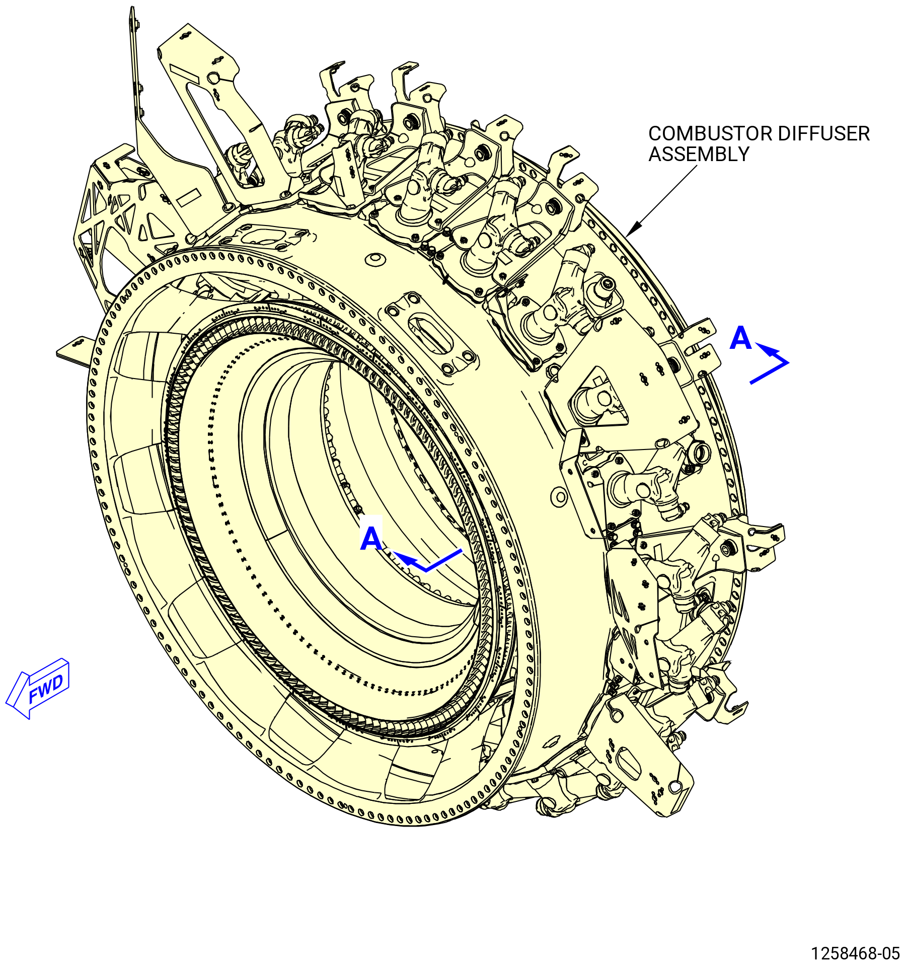
| A. | This procedure gives instructions to disassemble the combustor diffuser assembly (01-093 , 72-40-00) (SIN 12000) or (01-093A , 72-40-00) (SIN 12000). Refer to Figure 501. |
| B. | The combustor diffuser is on the 9429M60 roll-over stand with the 11C3052 restraint fixture installed. |
| C. | The fuel manifolds were removed in TASK 72-50-00-030-801 (72-50-00, DISASSEMBLY 001) . |
| D. | If the engine is operated in an abnormal condition, tag the parts for special inspections. Do an inspection of areas or parts exposed by removal of an assembly and note any discrepancies. |
| E. | The following procedure is applicable if the high pressure turbine (HPT) stage 1 nozzle is removed from the combustor diffuser assembly. |
| F. | Install protective caps on fuel nozzles when you remove them. |
| 2 . | Tools, Equipment, and Materials. |
| NOTE: |
|
| A. | Tools and Equipment. |
| (1) | Special Tools. |
| (2) | Standard Tools and Equipment. |
|
| (3) | Locally Manufactured Tools. None. |
| B. | Consumable Materials. |
|
| C. | Referenced Procedures. |
|
| D. | Expendable Parts. None. |
| 3 . | Procedure. |
| Subtask 72-41-00-040-042 |
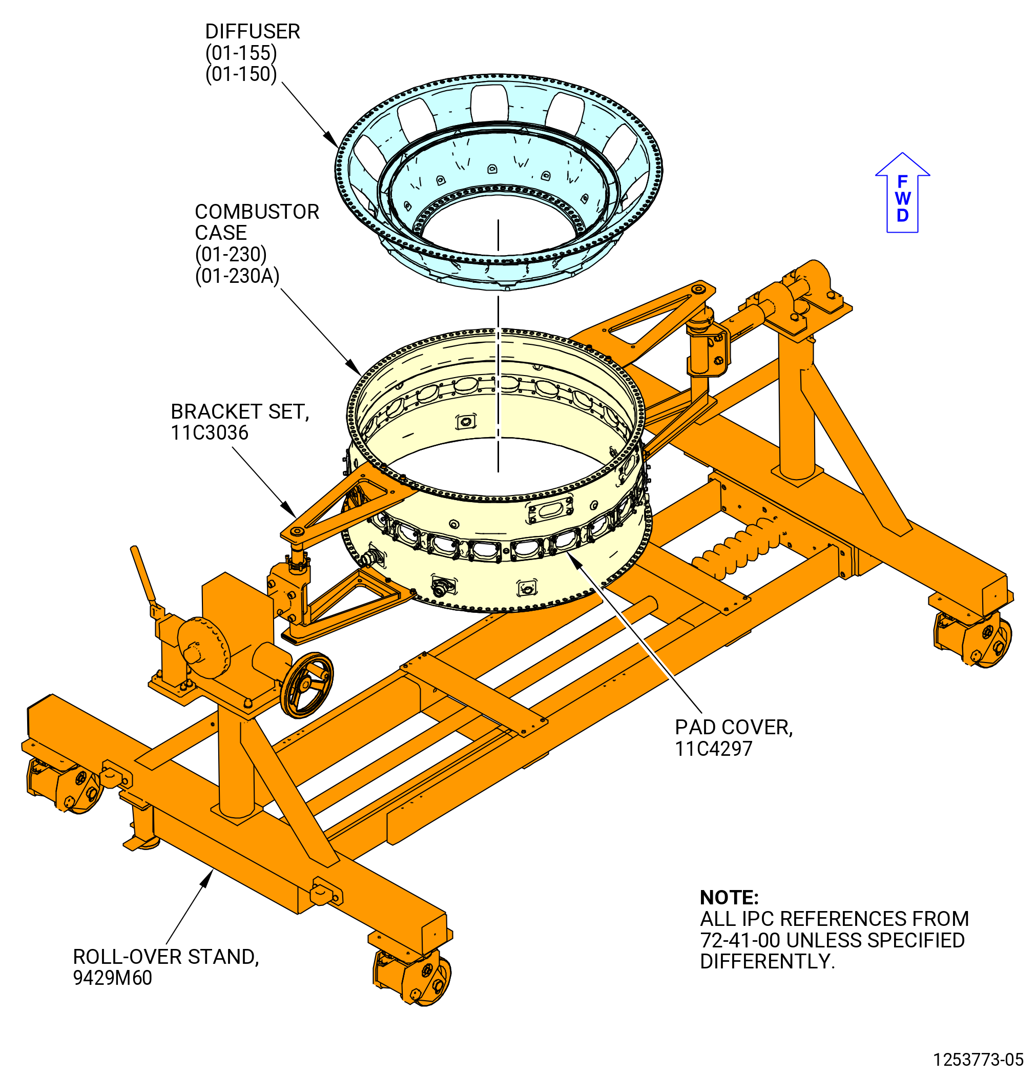
| A. | Make sure that the combustor diffuser assembly is correctly installed in the 9429M60 roll-over stand, aft end up, with the 11C3052 restraint fixture installed. Refer to Figure 502. |
| Subtask 72-41-00-040-043 |
| B. | Put location marks on the combustor case (01-230) (SIN 12001) or (01-230A) (SIN 12001) as follows: |
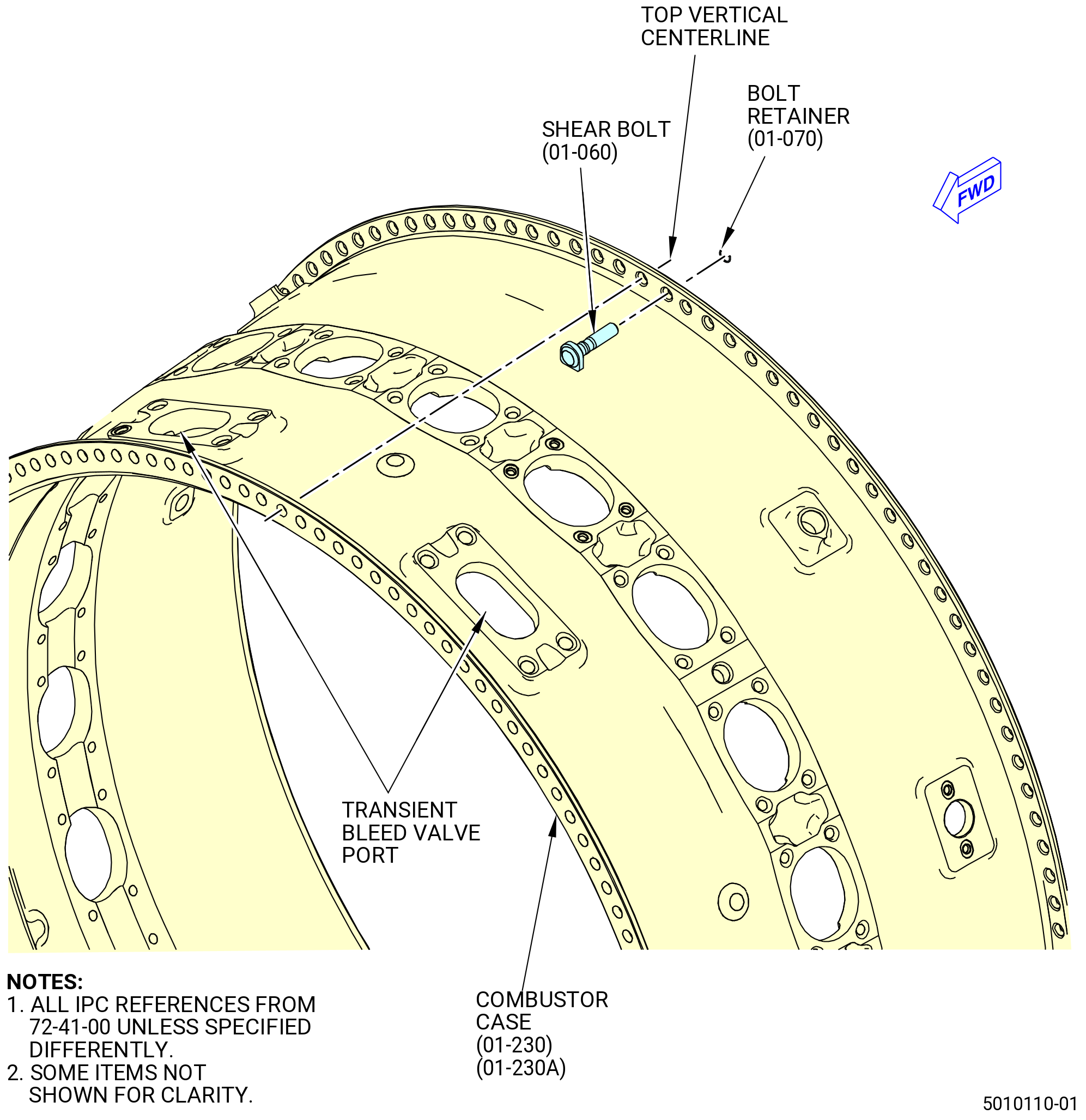
| (1) | Find the two transient bleed valve ports near the forward flange of the combustor case. The No. 1 fuel nozzle is aligned between the two transient bleed valve ports, at the top vertical center line (TVCL). Use the C05-003 pen to put a mark on the No. 1 fuel nozzle position. |
| (2) | Use the C05-003 pen to put a mark on the remaining fuel nozzle positions, clockwise (CW) aft looking forward, from fuel nozzle No. 2 thru fuel nozzle No. 22. |
| (3) | Find the center of the No. 1 fuel nozzle pad. This is the top vertical center line (TVCL) of the combustor case. Use the C05-003 pen to put a mark on the TVCL on the forward and aft flanges of the combustor case. |
| (4) | Locate the bolthole at TVCL on the aft flange of the combustor case. The offset bolthole is the first bolthole CCW of the bolthole at TVCL, aft looking forward (ALF). Use the C05-003 pen to put a mark on the offset bolthole location on the aft flange of the combustor case. |
| Subtask 72-41-00-040-044 |
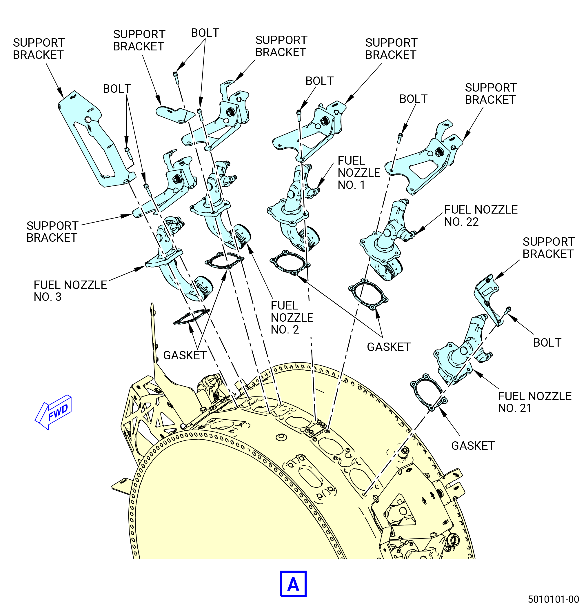
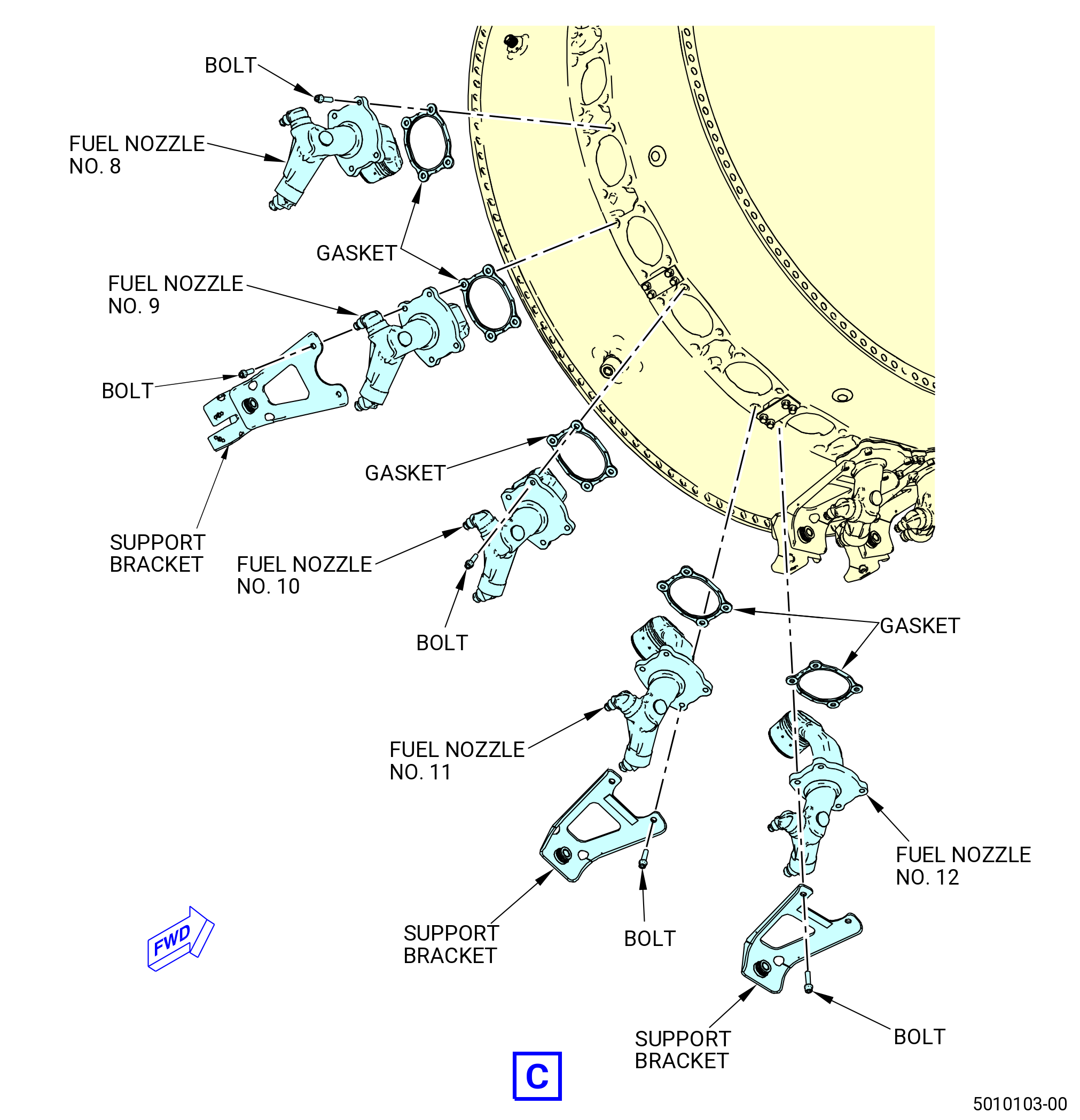
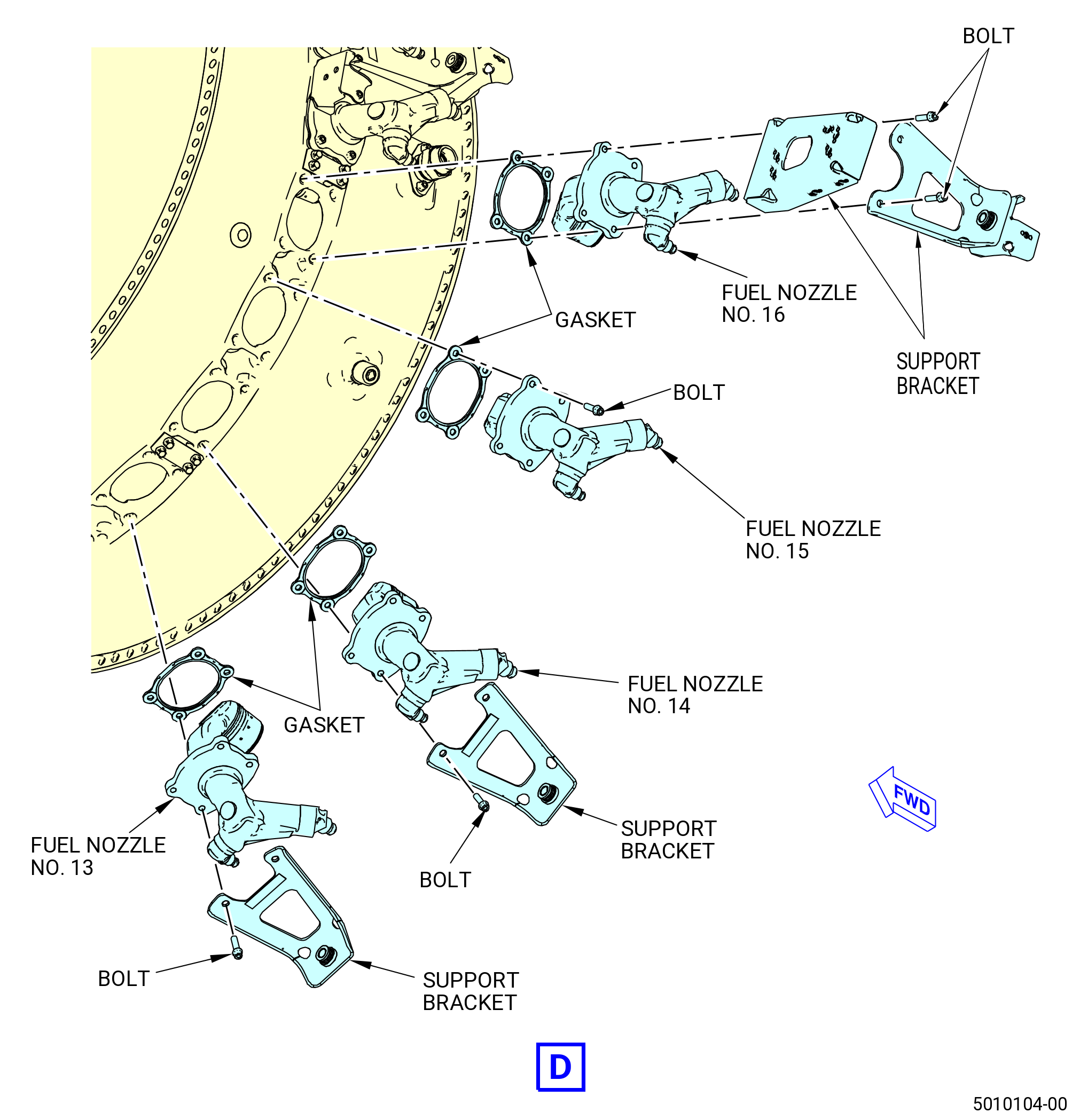
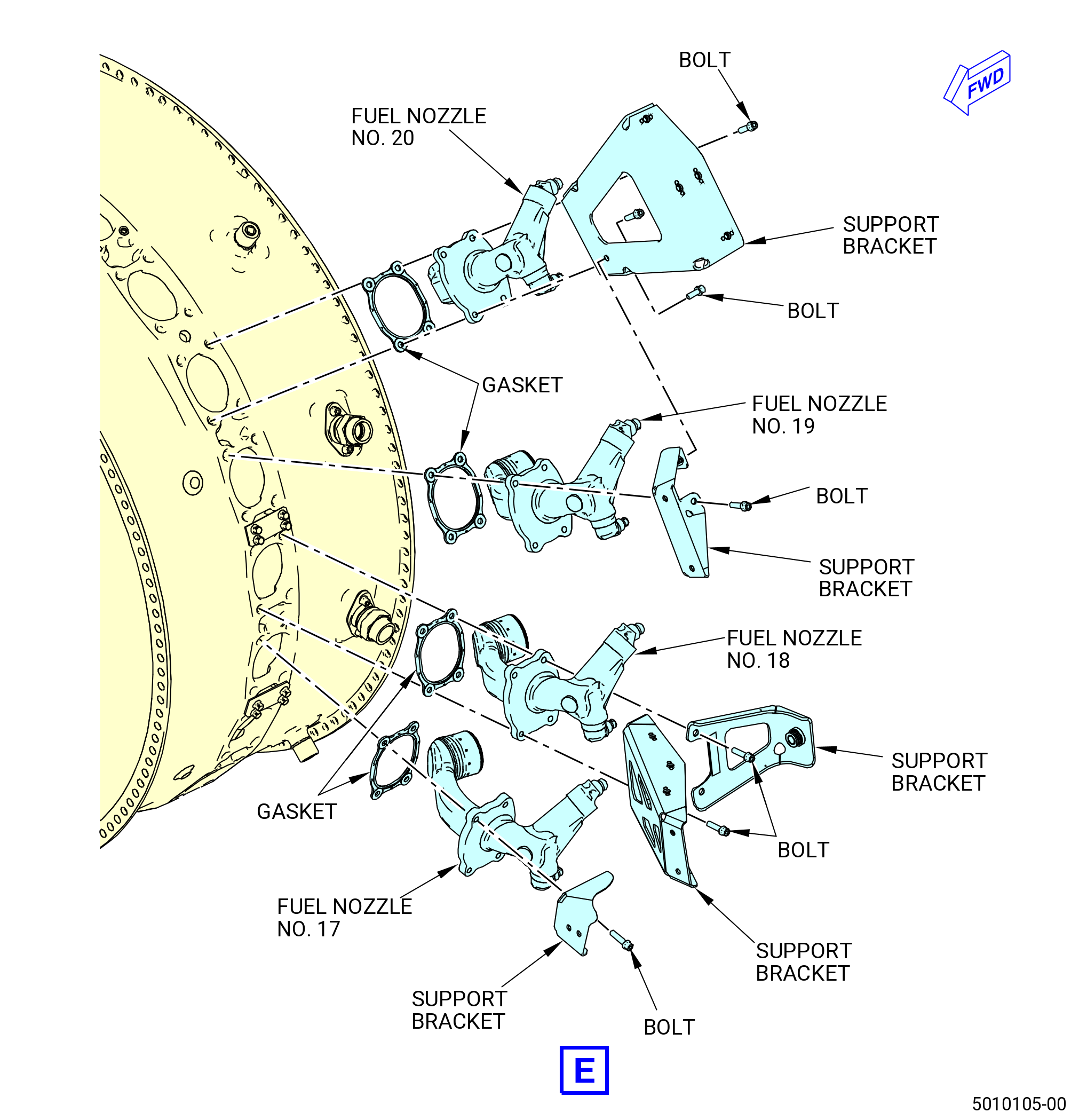
| C. | Remove the brackets and fuel nozzles from the combustor case (01-230) (SIN 12001) or (01-230A) (SIN 12001) as follows. Refer to Figure 503. |
| NOTE: |
|
| (1) | Remove and discard the bolts that attach the brackets and the fuel nozzles to the combustor case. |
| CAUTION: |
|
| (2) | If a bolt breaks during fuel nozzle removal, remove the broken bolt, refer to TASK 72-00-40-800-801 (72-00-40, SPECIAL PROCEDURES 001). |
| (3) | Remove the brackets and the fuel nozzles. |
| (4) | Remove and discard the fuel nozzle seal assemblies (06-020 , 73-11-30) (SIN 12550). |
| (5) | Remove and discard the preformed packings from the seal assemblies. |
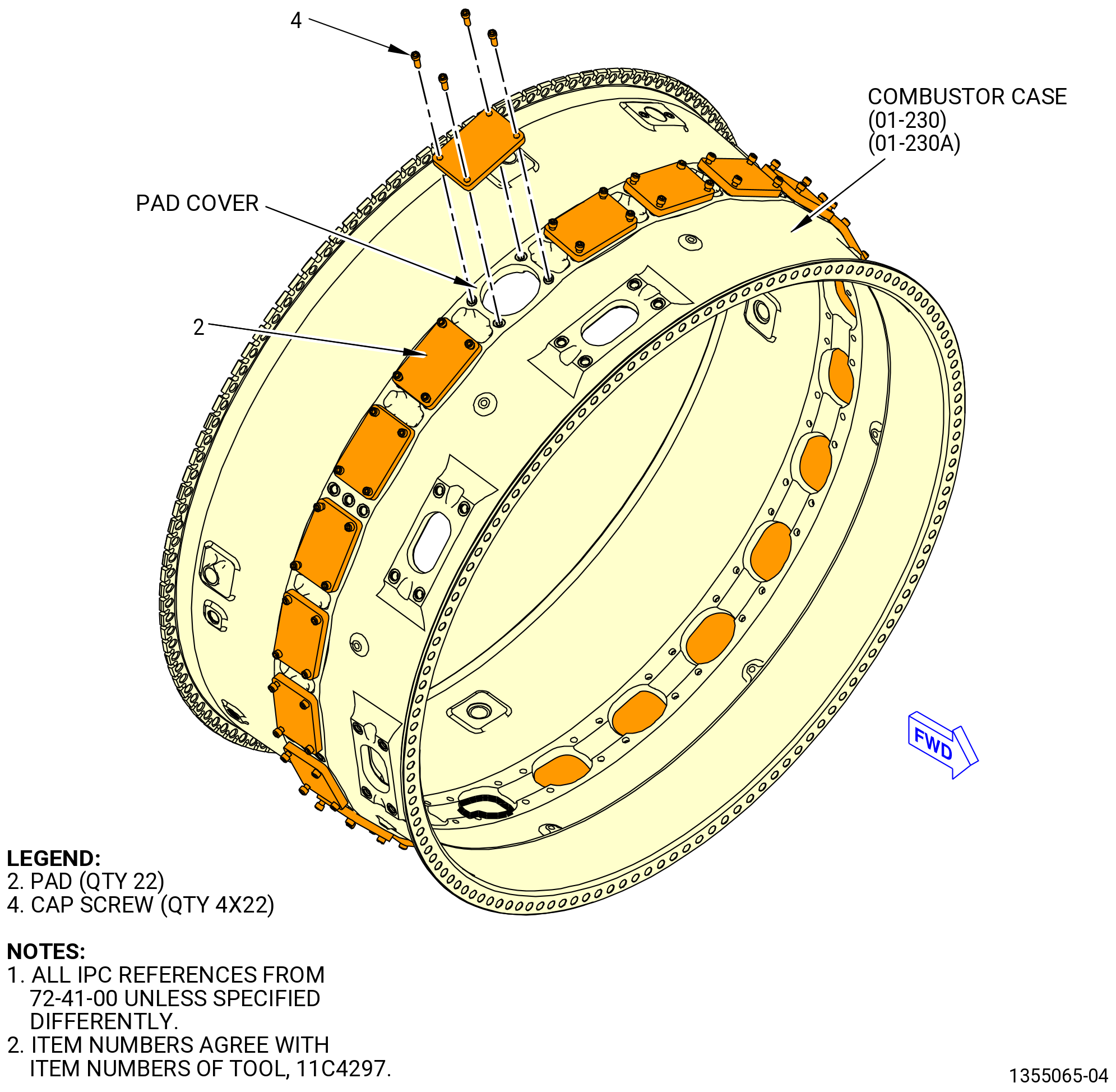
| D. | Install the 11C4297 pad covers on the combustor case (01-230) (SIN 12001) or (01-230A) (SIN 12001) as follows. Refer to Figure 504. |
| (1) | Install a pad (item 2) on the combustor case fuel nozzle pad using four cap screws (item 4). |
| (2) | Tighten the four cap screws (item 4) to 10 lb in. (1.1 N.m) to minimize wear on the threaded inserts in the combustor case. |
| (3) | Do again Subtask 72-41-00-040-044 paragraph 3.D.(1) thru paragraph 3.D.(2) for installation of each pad (item 2). |
| Subtask 72-41-00-040-045 |
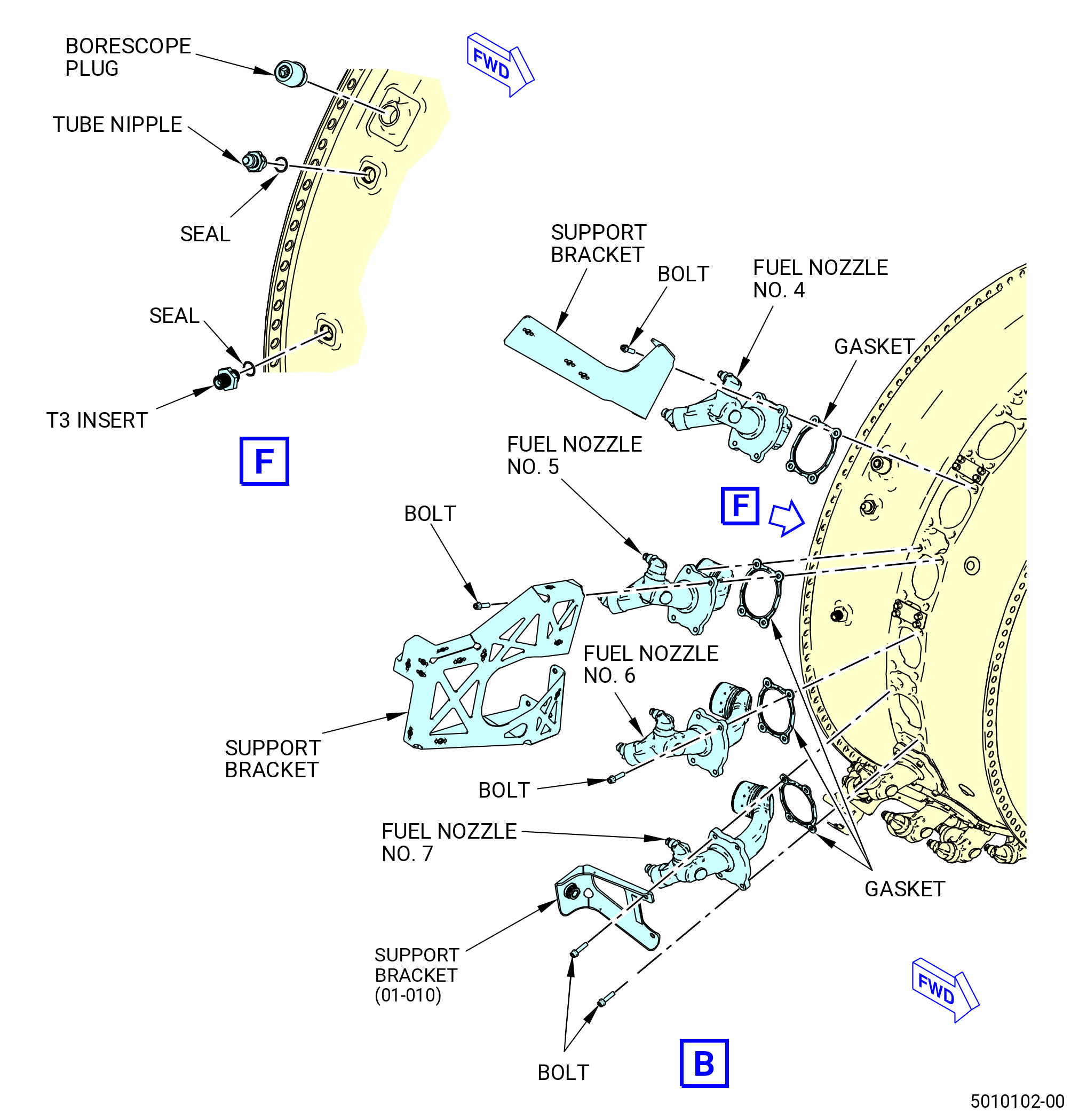
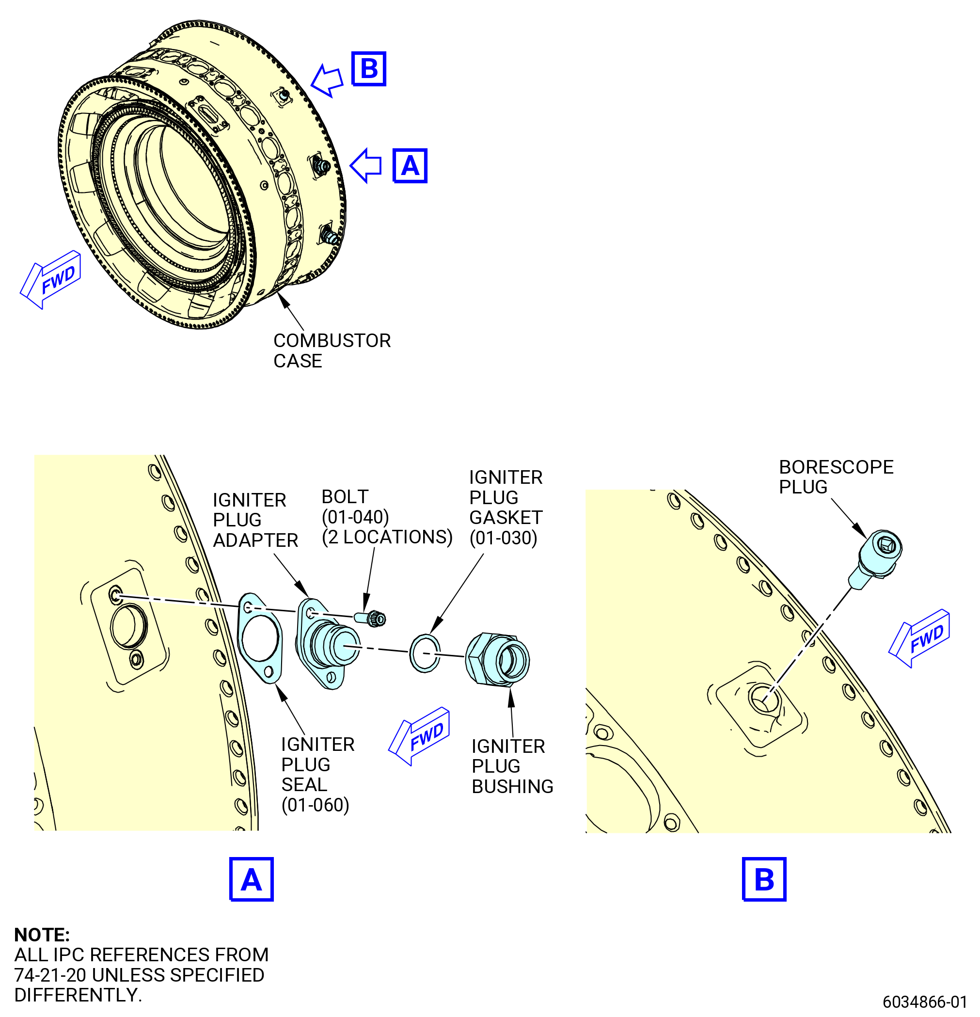
| E. | Remove the borescope plugs as follows. Refer to Figure 503 and Figure 505. |
| (1) | Remove the borescope plugs from the No. 4, No. 10, No. 15, and No. 21 fuel nozzle locations on the combustor case. |
| Subtask 72-41-00-040-046 |
| F. | Remove the T3 insert from the combustor case as follows. Refer to Figure 503. |
| (1) | Remove the T3 insert from the combustor case at the No. 6 fuel nozzle position. |
| (2) | Remove and discard the seal (01-070 , 73-21-10) (SIN 65N71) from the T3 insert. |
| Subtask 72-41-00-040-047 |
| G. | Remove the tube nipple from the combustor case as follows. Refer to Figure 503. |
| (1) | Remove the tube nipple from the combustor case between the No. 4 and No. 5 fuel nozzles. |
| (2) | Remove and discard the preformed packing (01-020) (SIN 61550) from the tube nipple. |
| Subtask 72-41-00-040-048 |
| H. | Remove the igniter plug adapters from the combustor case at the 8:45 o'clock and at 10:00 o'clock positions, refer to Figure 505 and as follows: |
| (1) | Remove the igniter plug bushings from the igniter plug adapters. |
| (2) | Remove and discard the igniter plug gaskets (01-030 , 74-21-20) (SIN 66270) from each of the adapters. |
| (3) | Remove and discard the bolts (01-040 , 74-21-20) (SIN 66220) that attach the igniter plug adapters to the combustor case. |
| (4) | Remove the igniter plug adapters from the combustor case. |
| (5) | Remove and discard the igniter plug seal assembly (01-060 , 74-21-20) (SIN 66250) from each of the igniter plug adapters. |
| Subtask 72-41-00-040-049 |
| I. | Remove the combustor assembly (01-092) (SIN 12400) or (01-093) (SIN 12400) from the combustor case as follows: |
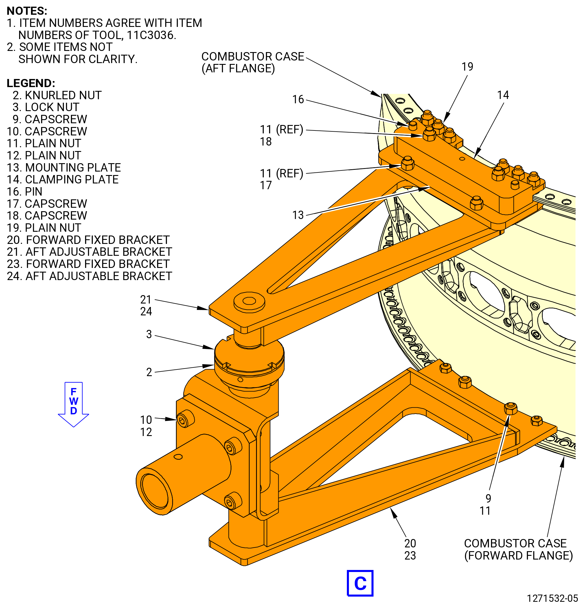
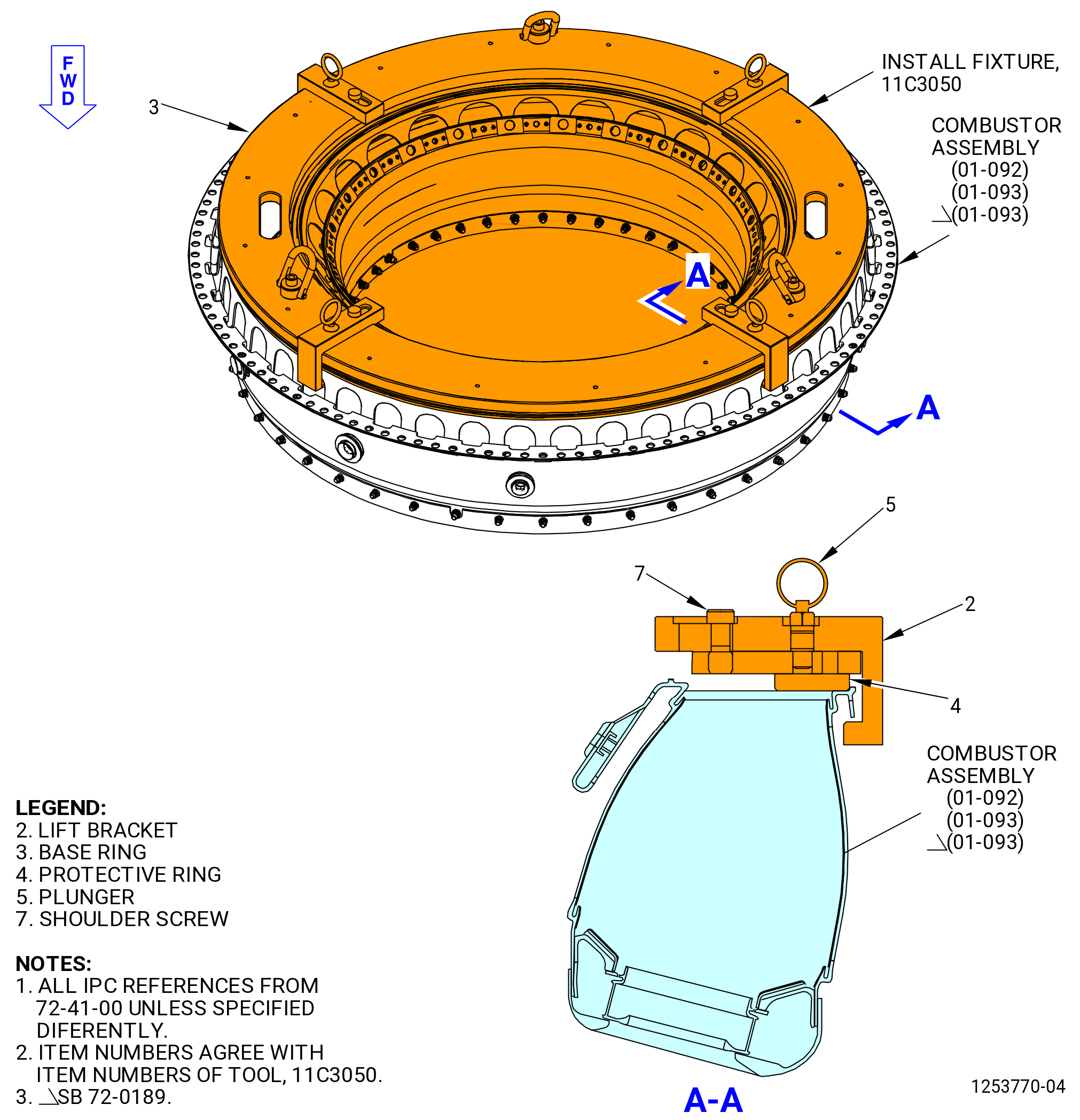
| (1) | Remove the nuts (item 11), nuts (item 19), capscrews (item 18), and clamping plate (14) that attach the 11C3036 bracket set to the combustor case aft flange to install the 11C3050 install fixture. Refer to Figure 502. |
| (2) | Attach the 11C3050 install fixture to the combustor assembly as follows. Refer to Figure 506. |
| (a) | Remove the plungers (item 5) and loosen the four shoulder screws (item 7). |
| (b) | Move the lift brackets (item 2) radially out. |
| WARNING: |
|
| (c) | Attach an overhead hoist to the three-legged sling. |
| (d) | Attach a three-legged sling to the 11C3050 install fixture and move it above the combustor case. |
| (e) | Lower the 11C3050 install fixture to the combustor assembly aft flange. |
| (f) | Make sure that the protective ring (item 4) is fully against the combustion chamber outer flange. |
| (g) | Move the lift brackets (item 2) radially in against the combustor assembly. |
| (h) | Tighten the four shoulder screws (item 7). |
| (i) | Install the four plungers (item 5) in the lift bracket (item 2). |
| (3) | Use the hoist to lift the combustor assembly from the combustor case. Put the combustor assembly on a table. |
| CAUTION: |
|
| (4) | Re-install the 11C3036 bracket set on the combustor case, remove nuts (item 11), nuts (item 19), capscrews (item 18), and clamping plate (14) that attach the 11C3036 bracket set to the combustor case aft flange to install the 11C3050 install fixture. Refer to Figure 502. |
| (5) | Remove the 11C3050 install fixture from the combustor assembly as follows: |
| (a) | Remove the four plungers (item 5) from the lift bracket (item 2). |
| (b) | Loosen the four shroud screws (item 7) and move the lift bracket (item 2) away from the combustion liner. |
| (c) | Use the hoist to remove the 11C3050 install fixture. |
| Subtask 72-41-00-040-050 |
| J. | Remove the combustor discharge manifold (09801) from the combustor case as follows. Refer to Figure 507. |
| (1) | Remove the self-locking nut (nut) (01-190) (SIN 09841) from the bolts that attach the combustor discharge manifold and the combustor case. Discard the nut. |
| (2) | Remove the bolts (09821) from the combustor discharge manifold and the combustor case. |
| (3) | Remove the bolts that attach the combustor discharge manifold to the diffuser. |
| Subtask 72-41-00-040-068 |
| * * * SB 72-0530 |
| (4) | Remove the bolts and washers that attaches the combustor discharge manifold to the diffuser. Discard the washers. |
| * * * END SB 72-0530 |
| Subtask 72-41-00-040-069 |
| (5) | Remove the combustor discharge manifold from the combustor case. |
| Subtask 72-41-00-040-051 |
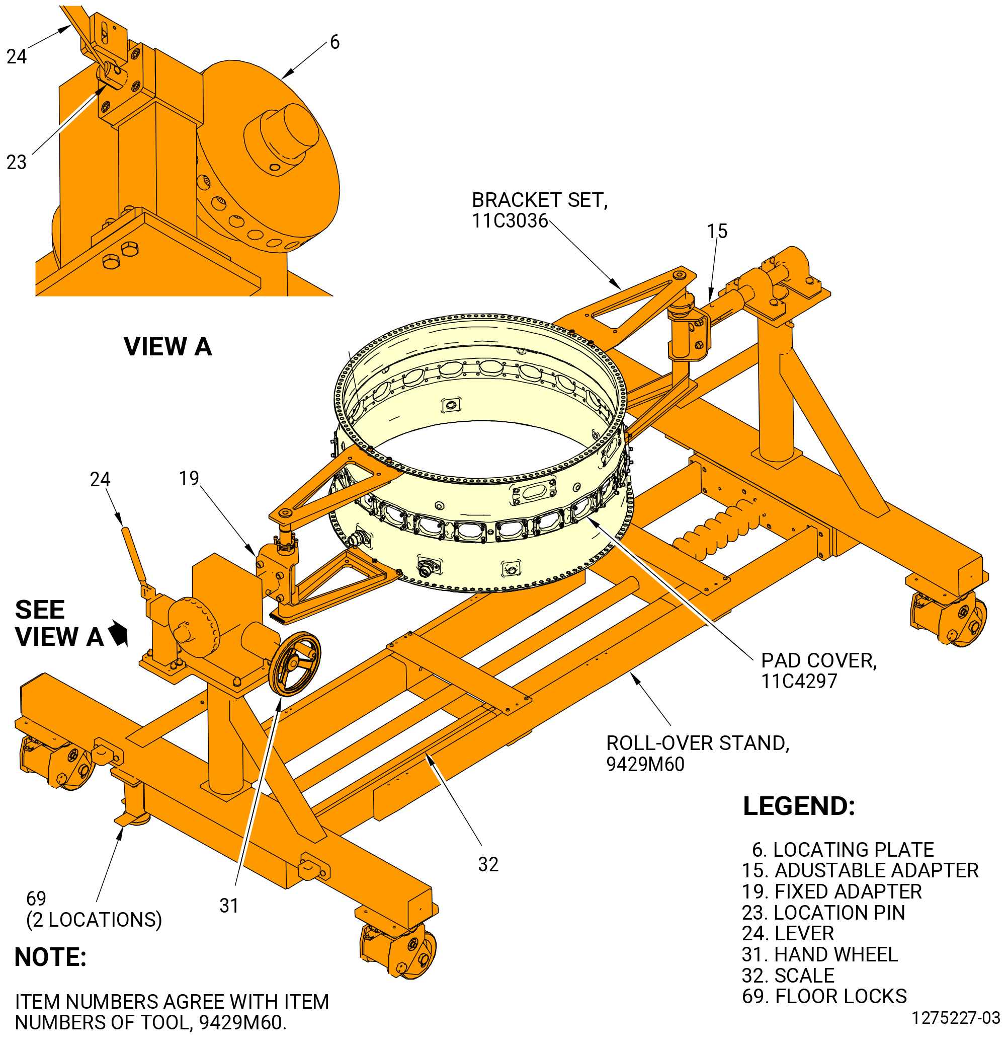
| K. | Turn the combustor case forward end up in the 9429M60 roll-over stand as follows. Refer to Figure 508. |
| CAUTION: |
|
| (1) | Make sure that the combustor case is correctly installed in the 11C3036 bracket set. |
| CAUTION: |
|
| (a) | Lower the floor locks (item 69) of the 9429M60 roll-over stand until they touch the floor. The floor locks must stay in contact with the floor to prevent movement of the roll-over stand. Make sure that the roll-over stand is level. |
| (2) | Push the lever (item 24) to unlock the hand wheel (item 31). |
| (3) | Turn the hand wheel (item 31) to put the forward end of the combustor case up. |
| CAUTION: |
|
| (4) | Pull the lever (item 24) to engage the locating pin (item 23) into the locating plate (item 6) to lock the hand wheel (item 31). |
| Subtask 72-41-00-040-052 |
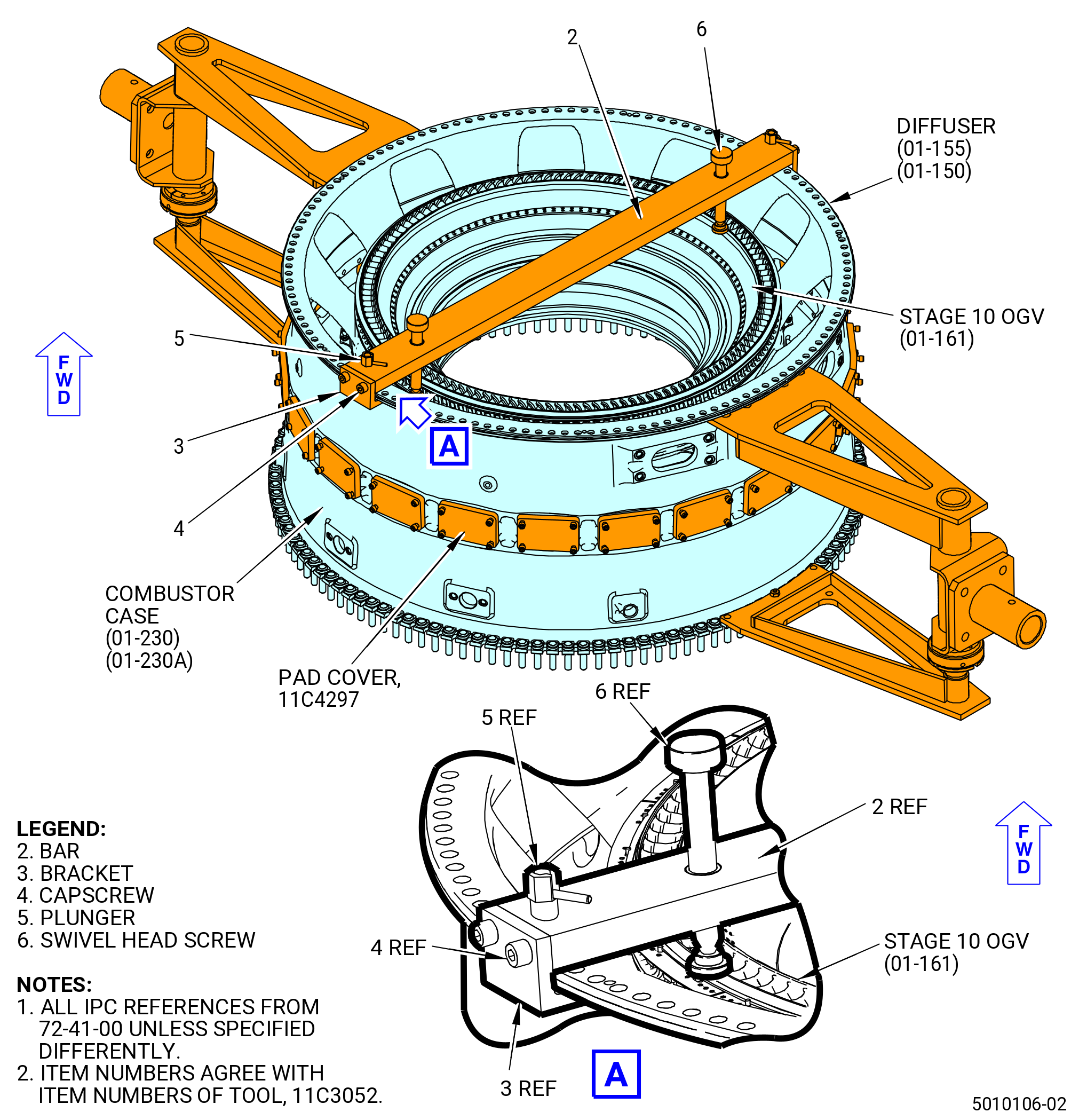
| L. | Remove the 11C3052 restraint fixture from the forward side of the combustor diffuser assembly as follows. Refer to Figure 509. |
| (1) | Turn the swivel head screws (item 6) CCW to retract them away from the stage 10 outlet guide vane (OGV). |
| (2) | Disengage the plungers (item 5) from the combustor case. |
| (3) | Move the bar (item 2) to the 4:00 o'clock and 8:00 o'clock positions of the combustor case. |
| (4) | Remove the 11C3052 restraint fixture from the combustor diffuser assembly. |
| Subtask 72-41-00-040-053 |
| M. | Alternative Procedure Available. Install the 11C3079 OGV lift fixture on the stage 10 OGV (01-161) (SIN 08001) as follows. Refer to Figure 510. |
| (1) | Turn the four vertical hand knobs (item 18) on the extension rods (item 5) clockwise (CW) to fully retract the segments of the lower clamp plate (item 25). |
| (2) | Turn the four horizontal hand knobs (item 18) CW to fully retract the segments of the upper clamp plate (item 24). |
| (3) | Turn the four knurled knobs (item 26) CCW to loosen the positioning stops (item 9). |
| (4) | Turn the adjustment nut (item 10) with the torque handle (item 4) to move the lower guide plate (item 6) and the upper guide plate (item 7) apart approximately 0.25 inch (6.4 mm). |
| (5) | Turn the hex head screw on the side of the fixator (item 44). |
| (6) | Turn the nut (item 42) CCW to lift it above the fixator (item 44). |
| (7) | Remove the ball lock pins (item 51) from the storage stand (item 31). |
| (8) | Move the retaining plates of the storage stand from the support beam (item 2). |
| WARNING: |
|
| (9) | Attach an overhead hoist to the lift eye (item 46) and lift the 11C3079 OGV lift fixture from the storage stand (item 31). |
| (10) | Align the 11C3079 OGV lift fixture above the stage 10 OGV. |
| (11) | Lower the 11C3079 OGV lift fixture on the combustor diffuser nozzle (CDN) assembly. Align the pins on the support beam (item 2) with two of the boltholes on the CDN forward flange. The positioning stops (item 9) will touch the forward face of the stage 10 OGV. |
| (12) | Attach the support beam (item 2) to the CDN forward flange with the capscrews (item 37). Torque the capscrews to 221-259 lb inch (25.0-29.3 N.m). |
| (13) | Adjust the lower clamp plate (item 25) radially until the segments lightly touch the inside diameter of the stage 10 OGV. Turn the nut (item 42) to adjust the axial position of the lower clamp plate. |
| (14) | Lower the fixator (item 44) into position and turn the nut (item 42) until the bottom edge of the lower clamp plate (item 25) is fully against the bottom edge of the stage 10 OGV. |
| (15) | Look through the holes in the upper guide plate (item 7) with a white light to make sure that the lower clamp plate is fully against the stage 10 OGV. Make sure that you can see the white scribed circle line on the lower guide plate. Make sure that the scribed circle line and the lower clamp plate (item 25) are concentric. |
| (16) | Turn the vertical hand knobs (item 18) CCW to tighten the lower clamp plate (item 25) against the stage 10 OGV. |
| (17) | Turn the horizontal knobs (item 18) CCW and move the upper clamp plate segments (item 24) until they lightly touch the inside diameter groove of the stage 10 OGV. |
| (18) | Use the torque handle (item 4) to turn the adjustment nut (item 10) up or down to align the radius of the 11C3079 OGV lift fixture with the radius of the stage 10 OGV. |
| (19) | Turn the horizontal knobs (item 18) CCW and tighten the upper clamp plate segments (item 24) against the inside diameter groove of the stage 10 OGV. |
| (20) | Look at the white circle line to make sure that the plates are concentric. |
| (21) | Move the positioning stops (item 9) above the stage 10 OGV flange. Tighten the knurled knobs (item 26) to hold the guide plates in position. |
| Subtask 72-41-00-040-054 |
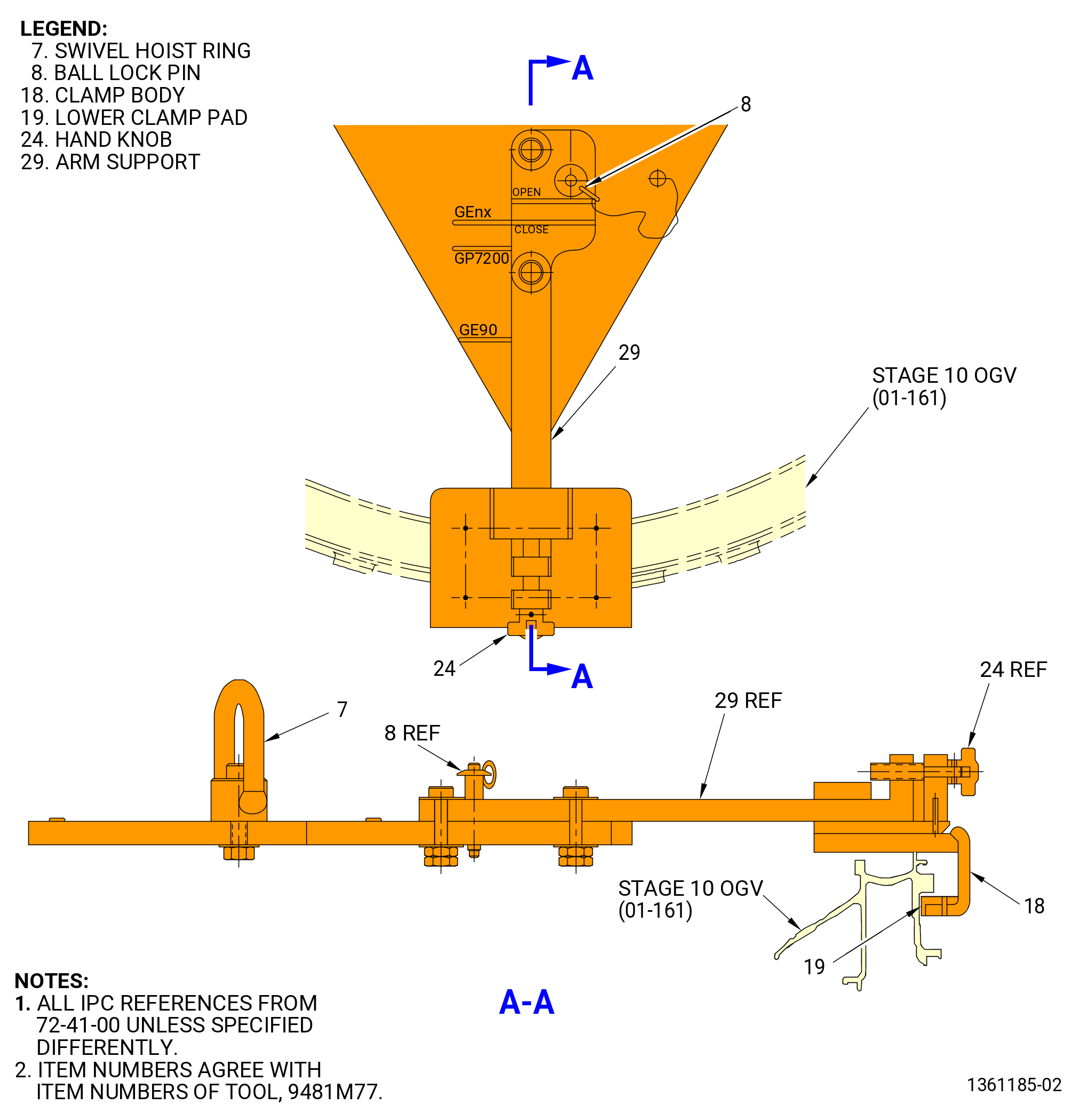
| M.A. | Alternative Procedure. Install the 9481M77 OGV lift/install fixture on the stage 10 OGV (01-161) (SIN 08001) and the diffuser (01-150) (SIN 09800) or (01-155) (SIN 09800) as follows. Refer to Figure 511. |
| (1) | Remove the ball-lock pins (item 8) from the three arm supports (item 29). |
| (2) | Turn each hand knob (item 24) to open the engagement diameter between the stage 10 OGV and the clamp body (item 18). |
| (3) | Put the 9481M77 OGV lift/install fixture on the stage 10 OGV. Make sure that the arm supports (item 29) are extended to the OPEN position for GEnx Engine application. |
| (4) | Install the arm supports (item 29) on the OGV as follows: |
| (a) | Put the arm supports (item 29) in the CLOSED position for the GEnx Engine application. |
| (b) | Insert the ball-lock pins (item 8) into the arm supports (item 29). |
| WARNING: |
|
| WARNING: |
|
| (5) | Turn the hand knob (item 24) to adjust the clamp body (item 18) until there is zero gap between the lower clamp pad (item 19) and the stage 10 OGV. |
| Subtask 72-41-00-040-055 |
| N. | Alternative Procedure Available. Remove the stage 10 OGV (01-161) (SIN 08001) from the diffuser (01-150) (SIN 09800) or (01-155) (SIN 09800) with the 11C3079 OGV lift fixture as follows. Refer to Figure 510. |
| (1) | Make sure that the upper clamp plate (item 24) and the lower clamp plate (item 25) are fully engaged. Use a white light and look through the holes in the upper guide plate (item 7) to make sure that the segments of the lower clamp plate are fully engaged. |
| (2) | Make sure that the acme nut (item 50) is 2.0 inches (51 mm) or more from the bottom of the support beam (item 2). |
| (3) | Turn the nut (item 42) with a wrench. |
| (4) | Turn the hex head screw on the side of the fixator (item 44) with a wrench to remove the stage 10 OGV from the diffuser. |
| (5) | Remove the capscrews (item 37) from the support beam (item 2) of the 11C3079 OGV lift fixture. Refer to Figure 510. |
| WARNING: |
|
| (6) | Use the hoist to remove the 11C3079 OGV lift fixture, with the stage 10 OGV installed, and put it on a clean surface. |
| (7) | Remove the 11C3079 OGV lift fixture from the stage 10 OGV as follows. Refer to Figure 510. |
| (a) | Use the torque handle (item 4) to turn the nut (item 10) CCW until the shoulder face of the lower plate (item 25) is disengaged from the stage 10 OGV. |
| (b) | Turn the capscrews (item 32) CW to retract the four segments of the lower plate (item 6). |
| (c) | Loosen the four positioning stops (item 9) from the stage 10 OGV. |
| (d) | Loosen the bolts (item 28) to retract the four segments of the upper guide plate (item 7). |
| (e) | Lift the 11C3079 OGV lift fixture from the stage 10 OGV. |
| Subtask 72-41-00-040-056 |
| (8) | Put the 11C3079 OGV lift fixture on the storage stand (item 31) as follows: |
| (a) | Lower the 11C3079 OGV lift fixture on the storage stand (item 31). |
| (b) | Move the retaining plates of the storage stand into position on the support beam (item 2). |
| (c) | Install the ball lock pins (item 51) in the retaining plates to attach the support beam (item 2) to the storage stand (item 31). |
| (d) | Remove the hoist from the lift eye (item 46). |
| Subtask 72-41-00-040-057 |
| N.A. | Alternative Procedure. Remove the stage 10 OGV (01-161) (SIN 08001) from the diffuser (01-150) (SIN 09800) or (01-155) (SIN 09800) with the 9481M77 OGV lift/install fixture as follows. Refer to Figure 511. |
| (1) | Connect the swivel hoist ring (item 7) to an overhead hoist with minimum lift capacity of 126 kg (278 lb). |
| (2) | Remove the stage 10 OGV from the diffuser with the 9481M77 OGV lift/install fixture as follows: |
| (a) | Remove the slave washers and the nuts from the shear bolts (01-100) (SIN 17221). |
| (b) | Use the hoist to lift the 9481M77 OGV lift/install fixture and stage 10 OGV and put it on a clean surface. |
| (c) | Remove the hoist from the swivel hoist ring (item 7). |
| (3) | Open the clamp body (item 18) by turning the hand knob (item 24) until there is sufficient clearance between the lower clamp pads (item 19) and the stage 10 OGV to remove the tool. |
| (4) | Remove the arm supports (item 29) from the stage 10 OGV as follows: |
| (a) | Remove the ball-lock pins (item 8). |
| (b) | Move the arm supports radially outwards until they are in the OPEN position for the GEnx Engine application. |
| (c) | Fully re-insert the ball-lock pins (item 8). |
| (5) | Remove the 9481M77 OGV lift/install fixture from the stage 10 OGV and store the 9481M77 OGV lift/install fixture tool. |
| Subtask 72-41-00-040-058 |
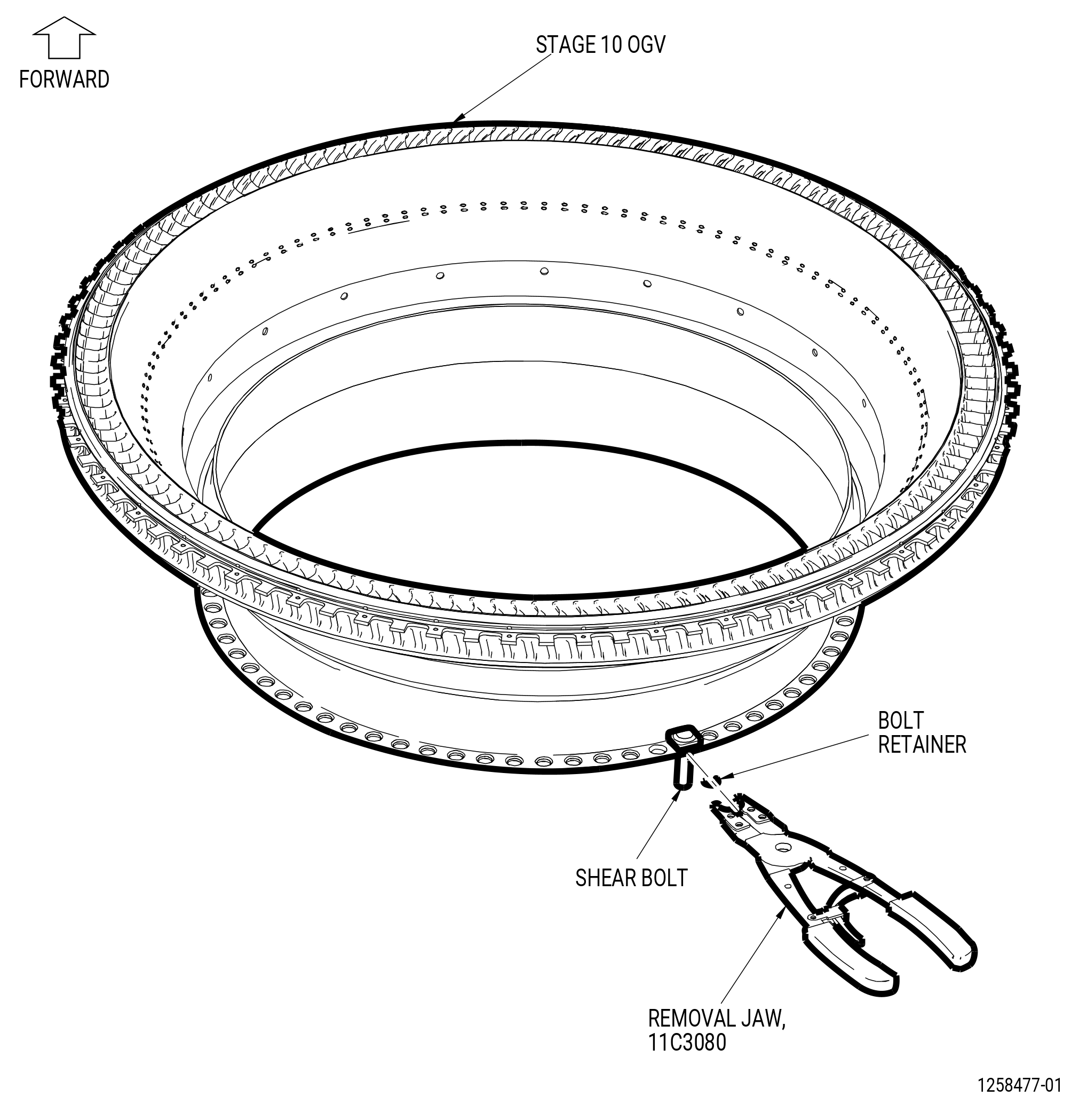
| O. | Remove the shear bolts (01-100) (SIN 17221) from the stage 10 OGV (01-161) (SIN 08001). Refer to Figure 512 and do as follows: |
| (1) | Put the removal jaw (item 3) of the 11C3080 retaining clip fixture around the bolt retainer (01-111) (SIN 17291) on the shear bolt. Align the split in the bolt retainer with the opening in the removal jaw. Close the removal plier (item 2) to engage the ends of the removal jaw with the ends of the bolt retainer. |
| (2) | Pull on the removal plier to pull the bolt retainer (01-111) (SIN 17291) from the shear bolt. |
| (3) | Remove and discard the shear bolt from the inner flange of the stage 10 OGV. |
| (4) | Do this procedure again to remove all the shear bolts. |
| Subtask 72-41-00-040-059 |
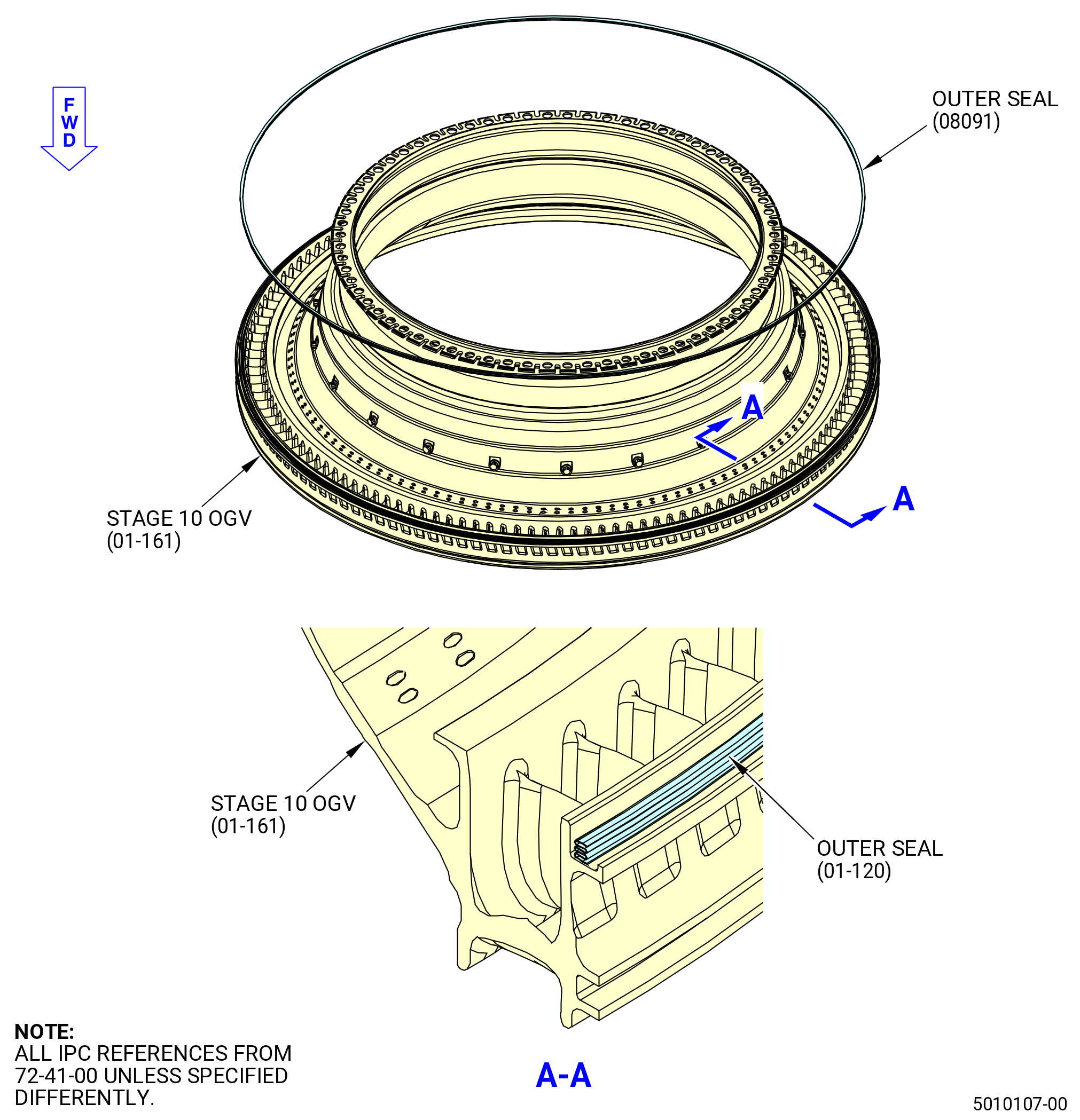
| P. | Remove the external pressure seal (01-120) (SIN 08091) from the stage 10 OGV (01-161) (SIN 08001). Discard the seal. Refer to Figure 513. |
| Subtask 72-41-00-040-065 |
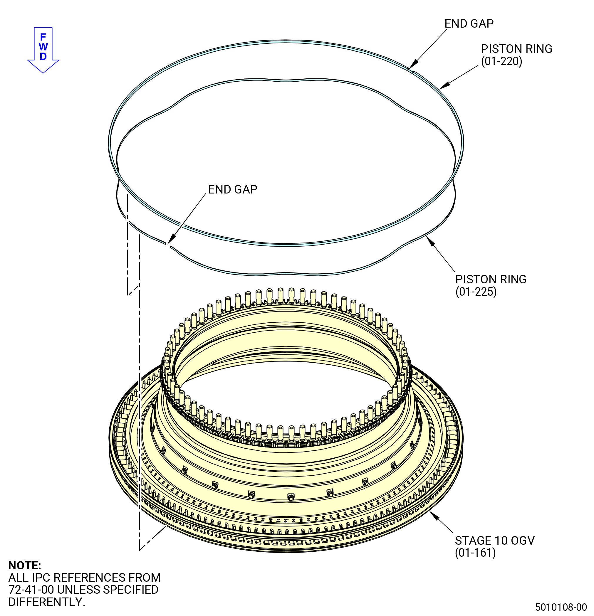
| Q. | Remove the piston rings (01-220) (SIN 122A0) and (01-225) (SIN 122A1) from the OD groove of the stage 10 OGV (01-161) (SIN 08001) and discard. Refer to Figure 514. |
| Subtask 72-41-00-040-060 |
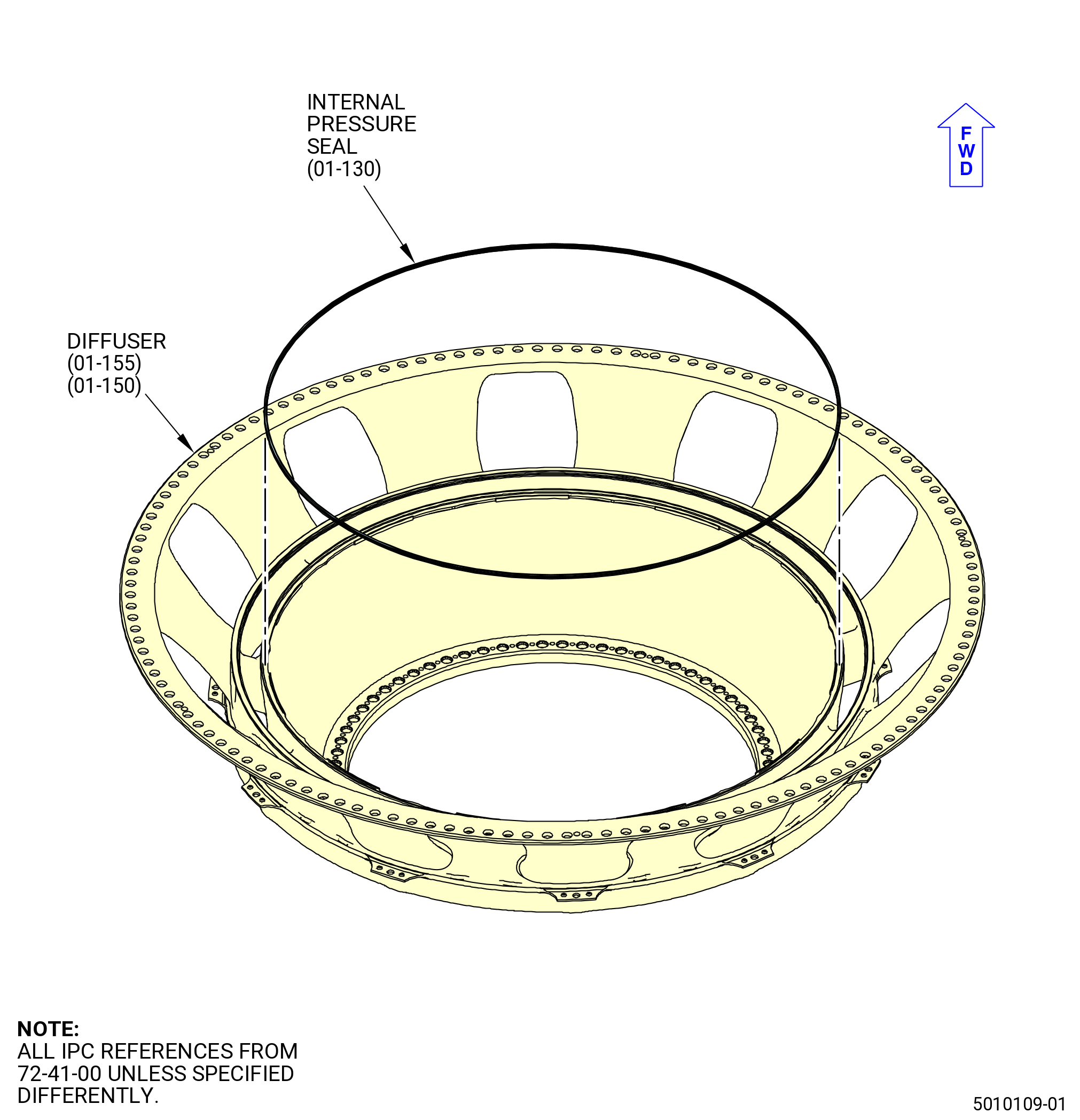
| R. | Remove the internal pressure seal (01-130) (SIN 08092) from the diffuser (01-150) (SIN 09800) or (01-155) (SIN 09800). Discard the seal. Refer to Figure 515. |
| Subtask 72-41-00-040-061 |
| S. | Remove the diffuser from the combustor case as follows. Refer to Figure 516: |
| WARNING: |
|
| (1) | Increase the temperature of the combustor case as follows: |
| NOTE: |
|
| (a) | Apply heat equally to the combustor case forward flange to a maximum temperature of 600°F (315.6°C). |
| (2) | Decrease the temperature of the diffuser to make disassembly easier as follows: |
| (a) | Apply dry ice equally to the diffuser forward flange. |
| (3) | Manually remove the diffuser from the combustor case and put it on a clean surface. |
| Subtask 72-41-00-040-062 |
| T. | Remove the combustor case from the 9429M60 roll-over stand as follows: |
| (1) | Turn the combustor case in the 9429M60 roll-over stand aft end up as follows. Refer to Figure 508. |
| CAUTION: |
|
| (a) | Make sure that the combustor case is correctly installed in the 11C3036 bracket set. |
| CAUTION: |
|
| (b) | Lower the floor locks (item 69) of the 9429M60 roll-over stand until they touch the floor. The floor locks must stay in contact with the floor to prevent movement of the roll-over stand. Make sure that the roll-over stand is level. |
| (c) | Push the lever (item 24) to unlock the hand wheel (item 31). |
| (d) | Turn the hand wheel (item 31) until the combustor case is in the aft end up position. |
| CAUTION: |
|
| (e) | Pull the lever (item 24) to engage the locating pin (item 23) into the locating plate (item 6) to lock the hand wheel (item 31). |
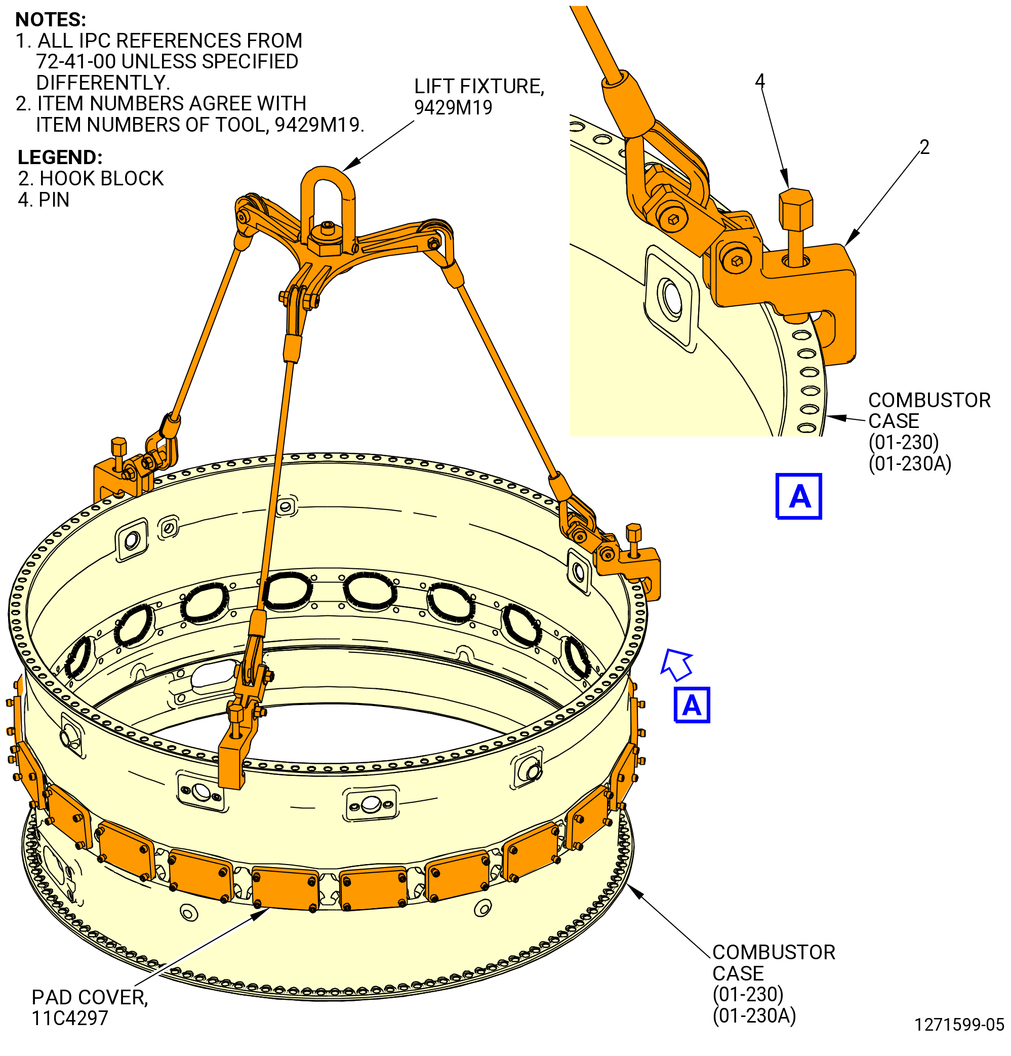
| (2) | Attach the 9429M19 lift fixture to the aft flange of the combustor case as follows. Refer to Figure 517. |
| (a) | Retract the pins (item 4) and install the hook blocks (item 2) on the flange at three equally spaced locations. |
| (b) | Align the pins (item 4) with the boltholes in the flange. |
| (c) | Engage the pins in the boltholes and the hook blocks (item 2). |
| Subtask 72-41-00-040-063 |
| WARNING: |
|
| (3) | Attach a hoist to the 9429M19 lift fixture and lift the combustor case to take the load off of the 9429M60 roll-over stand. |
| (4) | Remove the 11C3036 bracket set from the 9429M60 roll-over stand as follows. Refer to Figure 518. |
| CAUTION: |
|
| (a) | Remove the nuts (item 12) and capscrews (item 10) that attach the 11C3036 bracket set to the fixed adapter (item 19) of the 9429M60 roll-over stand and the adjustable adapter (item 15) of the 9429M60 roll-over stand. |
| (b) | Remove the combustor case, with the 11C3036 bracket set installed, from the 9429M60 roll-over stand. |
| (5) | Remove each bracket of the 11C3036 bracket set from the combustor case as follows: |
| NOTE: |
|
| (a) | Remove the nuts (item 11) and capscrews (item 9) that attach the forward fixed bracket (item 5) to the forward flange of the combustor case. |
| (b) | Remove the nuts (item 11) and capscrews (item 18) that attach the aft adjustable brackets (item 21) or (item 24) to the aft flange of the combustor case. |
| (c) | Loosen the locknut (item 3) and turn the knurled nut (item 2) CCW to retract the aft adjustable bracket (item 21) or (item 24) from the combustor case flange. |
| (d) | Disengage the pins of the forward fixed brackets (item 20) or (item 23) from the forward flange of the combustor case. |
| (e) | Remove the bracket. |
| (6) | Put the combustor case on a clean surface. |
| (7) | Remove the 9429M19 lift fixture from the combustor case. |
| Subtask 72-41-00-040-064 |
| U. | Remove the shear bolts (01-060) (SIN 12024) from aft flange of the combustor case. Refer to Figure 519 and do as follows: |
| (1) | Put the removal jaw (item 3) of the 11C3080 retaining clip fixture around the bolt retainer (01-070) (SIN 12080) on the shear bolt. Align the split in the bolt retainer with the opening in the removal jaw. Close the removal plier (item 2) to engage the ends of the removal jaw with the ends of the bolt retainer. |
| (2) | Pull on the removal plier to pull the bolt retainer (01-070) (SIN 12080) from the shear bolt. |
| (3) | Remove the shear bolt from the aft flange of the combustor case. |
| (4) | Do this procedure again to remove all the shear bolts. |