| COMMERCIAL ENGINE STANDARD PRACTICES MANUAL | Dated: 07/18/2016 | |
| SPM 70-32-23 EDDY CURRENT INSPECTION OF DOVETAIL SLOT BOTTOMS IN ENGINE ROTATING HARDWARE USING AN AUTOMATED INSPECTION SYSTEM | ||
| COMMERCIAL ENGINE STANDARD PRACTICES MANUAL | Dated: 07/18/2016 | |
| SPM 70-32-23 EDDY CURRENT INSPECTION OF DOVETAIL SLOT BOTTOMS IN ENGINE ROTATING HARDWARE USING AN AUTOMATED INSPECTION SYSTEM | ||
| TASK 70-32-23-250-801 |
| 1 . | General. |
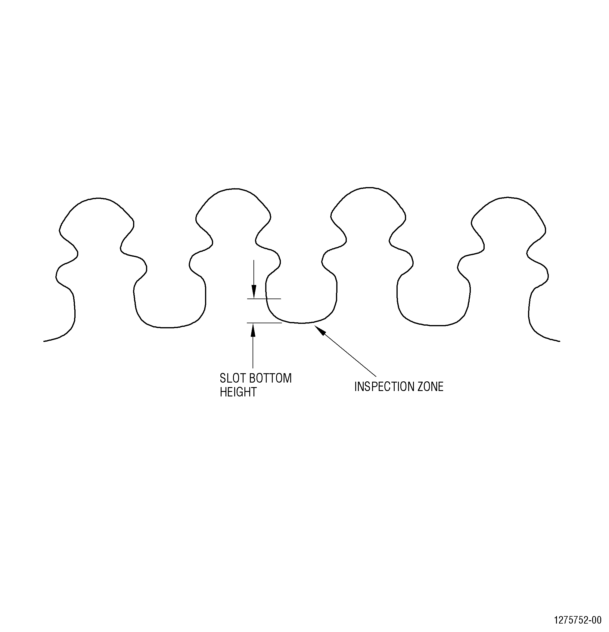
| A. | This document describes the equipment, techniques, and procedures for conducting component level 2 MHz eddy current inspections of dovetail slot bottoms in engine run rotating hardware manufactured from titanium, inconel, and rene alloys. The inspection areas, and specific requirements are detailed in the appropriate service bulletins and engine shop manuals. Refer to Figure 1 for an example inspection area. |
| B. | Automated inspection systems must be used for this inspection. |
| C. | For specific cases where the procedure or equipment described in this document cannot be applied in their total content, specific exceptions must be obtained in writing from GE Aviation to document the deviation. |
| 2 . | Applicable Documents. |
| Subtask 70-32-23-250-001 |
| A. | The following documents must form a part of this procedure to the extent specified herein. Unless a specific issue is specified, the latest revision must apply. |
| (1) | Appropriate equipment instruction manuals. |
| (2) | NAS-410 (latest revision). |
| (3) | Appropriate Service Bulletin or Engine Shop Manual procedure. |
| 3 . | Personnel Requirements. |
| Subtask 70-32-23-250-002 |
| A. | The following requirements must be met by inspection personnel: |
| (1) | Personnel performing this inspection must be certified in accordance with NAS-410, American Society of Nondestructive Testing (ASNT-TC-1A, Air Transport Association Specification No. 105 (ATA 105), COSAC, or any equivalent certification document acknowledged by the local regulatory agencies. |
| (2) | It is strongly recommended that personnel performing this inspection receive practical training in the use of this procedure and must demonstrate proficiency in the calibration, inspection and evaluation routines before accept/reject authority is delegated. |
| (3) | Any training, which can be provided regarding the performance of this inspection does not imply that, the personnel who receive that training has met the requirements for inspector certification in accordance with the appropriate certification document. |
| 4 . | Equipment. |
| Subtask 70-32-23-250-003 |
| A. | The instrumentation/tooling listed in this section does not include all of the equipment necessary to perform this inspection, but does include all items for which substitution cannot be made without written approval from GE Aviation. |
| B. | System and Instrumentation. |
| NOTE: |
|
| (1) | Eddy current inspection system. |
| (a) | The automated inspection system used must be comprised of at least six (6) axes, one of which is a turntable providing movement in a rotary direction (C axis). |
| (b) | The inspection system used must be capable of accurately indexing the eddy current probe around the dovetail slot bottom being inspected and accurately moving the probe along the length of the dovetail slot while keeping the coil perpendicular to the inspection surface. |
| (c) | The capability of this system must be demonstrated to GE Aviation prior to approval for this inspection procedure. |
| (d) | The system mechanical accuracies must meet the requirements described in Table 1 and must be checked annually. |
| (e) | A list of approved systems and manufacturers for this equipment is available from: |
| 1 | GE Aviation, QTC. Refer to the list of suppliers in TASK 70-80-00-800-803, Consumable Materials Section, paragraph 4. |
| (f) | The system mechanical parameters described in Table 2 are to be used for six axis articulate arm robot for eddy current systems. Measure and record the maximum indicator measurement or runout for each data set described in Table 2 over a 12 inch (304.8 mm) minimum move between two taught points, zeroing the indicator at each end throughout the work envelope. The use of precision square, parallel bars with a dial indicator mounted on the T axis face of the robot or other suitable location will be required. All equipment used must be within calibration dates. Systems that have a turn table must have a robot user frame or offline virtual user frame set at the center of table. |
|
||||||||||||||||||||||||||||||||||||||||||||||||||||||||||||||||||||||||||||||||||||||||||||||||||||||||||||||||||||||||||||||||||||||||||||||||||||
| NOTE: |
|
| (2) | Eddy Current Instruments. |
| (a) | Uniwest 454. |
| (3) | Data Recording Instruments/Systems. |
| (a) | Uniwest 454 eddy current instrument with data buffer. |
| (b) | Equivalent data recording system approved by GE Aviation. |
| C. | Tooling. |
| (1) | Calibration standard: Calibration standards will be specified in the appropriate Engine/Shop Manual or service bulletin for the part to be inspected. |
| (2) | Eddy current probe: The probe to be used will be specified in the appropriate Engine/Shop Manual or service bulletin for the specific hardware to be inspected. |
| (3) | Eddy current probe fixture manufactured by Uniwest P/N 99070 or equivalent approved by GE Aviation. |
| D. | Eddy current tooling can be obtained by contacting the following: |
| (1) | GE Aviation, QTC. Refer to the list of suppliers in TASK 70-80-00-800-803, Consumable Materials Section, paragraph 4. |
| E. | Materials. |
|
| 5 . | Pre-Inspection Part Preparation. |
| Subtask 70-32-23-250-004 |
| A. | Visually inspect the features to be scanned under white light for evidence of adhering dirt, cracks, rubbing, fretting, etc. |
| B. | Clean the features by using C10-010 abrasive cloth. Refer to Subtask 70-32-22-250-001, Generic Eddy Current Inspection of CF6 Slot Bottoms. |
| C. | Prior to inspection, locate the number 1 dovetail slot on the part. Mark this location on the part using an approved marker. Refer to TASK 70-16-02-350-017, Temporary Marking. This will be the start position. |
| D. | Center the part on the turntable within 0.005 inch (0.13 mm) or less and adjust the disk post face flat to the table to 0.005 inch (0.13 mm) or less. |
| 6 . | Equipment Set-Up. |
| Subtask 70-32-23-250-005 |
| A. | Connect the equipment and allow it to warm up in accordance with the manufacturer’s specifications. |
| B. | Prepare C10-040 Teflon tape for probe wear face as follows: |
| (1) | Lay a strip of C10-040 Teflon tape approximately 1.0 inch (25.4 mm) long on a firm, smooth, clean surface. With a razor blade cut the Teflon tape to a length that will sufficiently cover the probe face. |
| (2) | Apply the tape tightly across the coil face. Do not allow the tape to extend past the end of the probe. Cover only the face of the coil. |
| C. | Insert the eddy current probe into the probe holder. |
| D. | Connect the probe to the eddy current instrument front panel receptacle. |
| E. | Adjust the instrument control settings as follows: |
|
|||||||||||||||||||||||||||||||||||||||||||||||||||||||||||||||||||||||||||||||||||||||||||||||||||||||||||||||||||||||||||||||||||||||||||||||||||||||||||||||||||||||||||||||||||||||||||||||||||||||||||||||||||||||||||||||||||||||||||||||
| F. | Adjust the standard so the eddy current probe stem will travel parallel to the length of the EDM (electrodischarge machined) notch. |
| 7 . | Equipment Calibration. |
| Subtask 70-32-23-250-006 |
| A. | Connect the equipment and set initial settings. Refer to Subtask 70-32-23-250-005, Equipment Set-up. |
| B. | Position the probe on the calibration standard. |
| C. | Apply approximately 0.275 inch (7.0 mm) of spring compression on the probe fixture. Null the eddy current instrument with the probe on the calibration standard surface away from the EDM notch and engraving. |
| D. | Null the eddy current instrument. |
| E. | Scan across the standard in a direction parallel to the EDM notch at a speed of 4 inches (101.6 mm) per second. |
| F. | Index the probe across the EDM notch at a maximum increment of 0.015 inch (0.38 mm). |
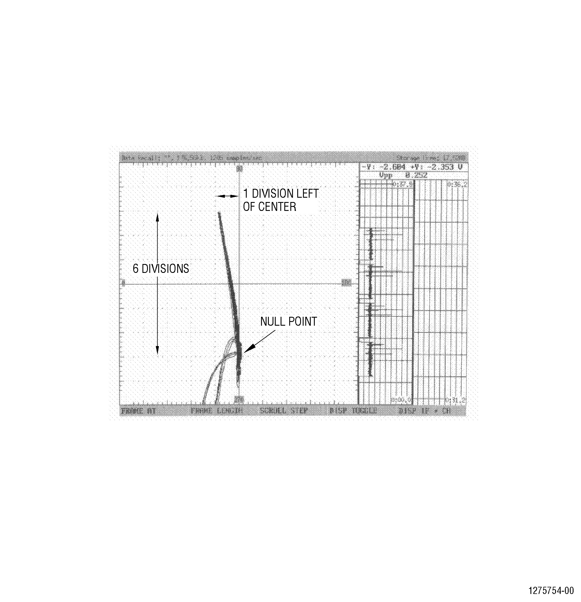
| G. | Adjust the gain and angle on the US-454 instrument until the maximum vertical signal is 6 major divisions from null point, and horizontal 1 major division to left of center. Refer to Figure 2. |
| H. | Repeat the scan as required to achieve the correct calibration. |
| I. | The final scan must display at least 3 responses from the EDM notch, with the peak response at 6 major divisions and in the center of the display. |
| J. | Record all calibration data onto the appropriate calibration log contained in the scan logs. |
| 8 . | Part Inspection. |
| Subtask 70-32-23-250-007 |
| A. | Complete pre-inspection part preparation. Refer to Subtask 70-32-23-250-004, Pre-Inspection Part Preparation. |
| B. | Calibrate. Refer to Subtask 70-32-23-250-006, Equipment Calibration. |
| C. | Refer to the appropriate service bulletin, engine shop manual for the appropriate inspection areas and inspect all dovetail slots. |
| D. | Inspect each dovetail slot a surface scanning speed of 4 inches (101.6 mm) per second. |
| NOTE: |
|
| E. | Index across the dovetail slot bottom inspection area at an increment of 0.015 inch (0.38 mm). |
| F. | Make sure that complete coverage of the inspection area of each dovetail slot is obtained. |
| G. | Renulling is required for each dovetail slot. |
| H. | Evaluate all repeatable indications with amplitudes greater than or equal to the limit specified in the appropriate service bulletin or engine shop manual. Refer to Subtask 70-32-23-250-009, Indication Evaluation. |
| I. | Complete the inspection of all of the dovetail slots. |
| J. | Record all inspection results on the appropriate Operator’s scanning log. |
| 9 . | Post Calibration. |
| Subtask 70-32-23-250-008 |
| A. | Calibrate before and after inspecting a part, whenever an equipment change is made, whenever a power outage occurs, or whenever the operator suspects a problem. |
| B. | If the notch response is less than 5.5 divisions, the calibration check is not acceptable, the system must be re-calibrated and all slots inspected since the last successful calibration check must be re-inspected. |
| C. | If the notch response is greater than 6.5 divisions, the calibration check is acceptable, but, the system should be re-calibrated before performing additional inspections and any slots rejected since the last successful calibration check should be re-inspected. |
| D. | If the notch response is 6 major screen divisions plus or minus one-half major division, the calibration check is acceptable. |
| 10 . | Indication Evaluation. |
| Subtask 70-32-23-250-009 |
| A. | Initially, all indications with amplitudes greater than or equal to the limit specified in the appropriate service bulletin, engine shop manual or inspection scan plan are considered rejectable. |
| NOTE: |
|
| B. | Clean the area of indication with C10-010 abrasive cloth and approved C04-035 solvent or C04-003 solvent and re-inspect the area. If the indication is reduced to below the reject level, it must be considered acceptable and noted. If not, continue to evaluate the indication as detailed below. |
| C. | Carefully examine the area of the indication under bright white light using a 5x/10x glass. Note any unusual conditions such as discoloration, handling damage, uneven surfaces, or raised metal, and record these conditions. |
| D. | Re-clean and re-inspect the area. The following must apply: |
| (1) | If the indication amplitude falls below the reject level, the area must be considered acceptable and noted. |
| (2) | If the indication amplitude is reduced but still greater than the reject level, re-clean and re-evaluate the area since the indication is most likely due to surface contamination. |
| (3) | If the indication amplitude does not fall below reject level, reject the part and identify it for further engineering evaluation and disposition. Record the indication number, area, amplitude, background noise, location, and comments (visual findings) on the Certificate of Conformance. |
| 11 . | Records. |
| Subtask 70-32-23-250-010 |
| A. | Document all inspection results. As a minimum, document and maintain the calibration logs and operator scan logs with the inspection data package. |
| B. | It is the Inspection Facility’s responsibility to maintain all inspection records. The inspection records must be kept with the permanent record of the part and must be maintained for the life of the part. |