| GENX-1B CLEANING,INSPECTION,AND REPAIR MANUAL | Dated: 07/26/2022 | |
| CIR 72-22-40 , INSPECTION 001 | ||
| STAGE 1 FAN DISK - INSPECTION | ||
| GENX-1B CLEANING,INSPECTION,AND REPAIR MANUAL | Dated: 07/26/2022 | |
| CIR 72-22-40 , INSPECTION 001 | ||
| STAGE 1 FAN DISK - INSPECTION | ||
| * * * FOR ALL |
| TASK 72-22-40-200-801 |
| 1 . | General. |
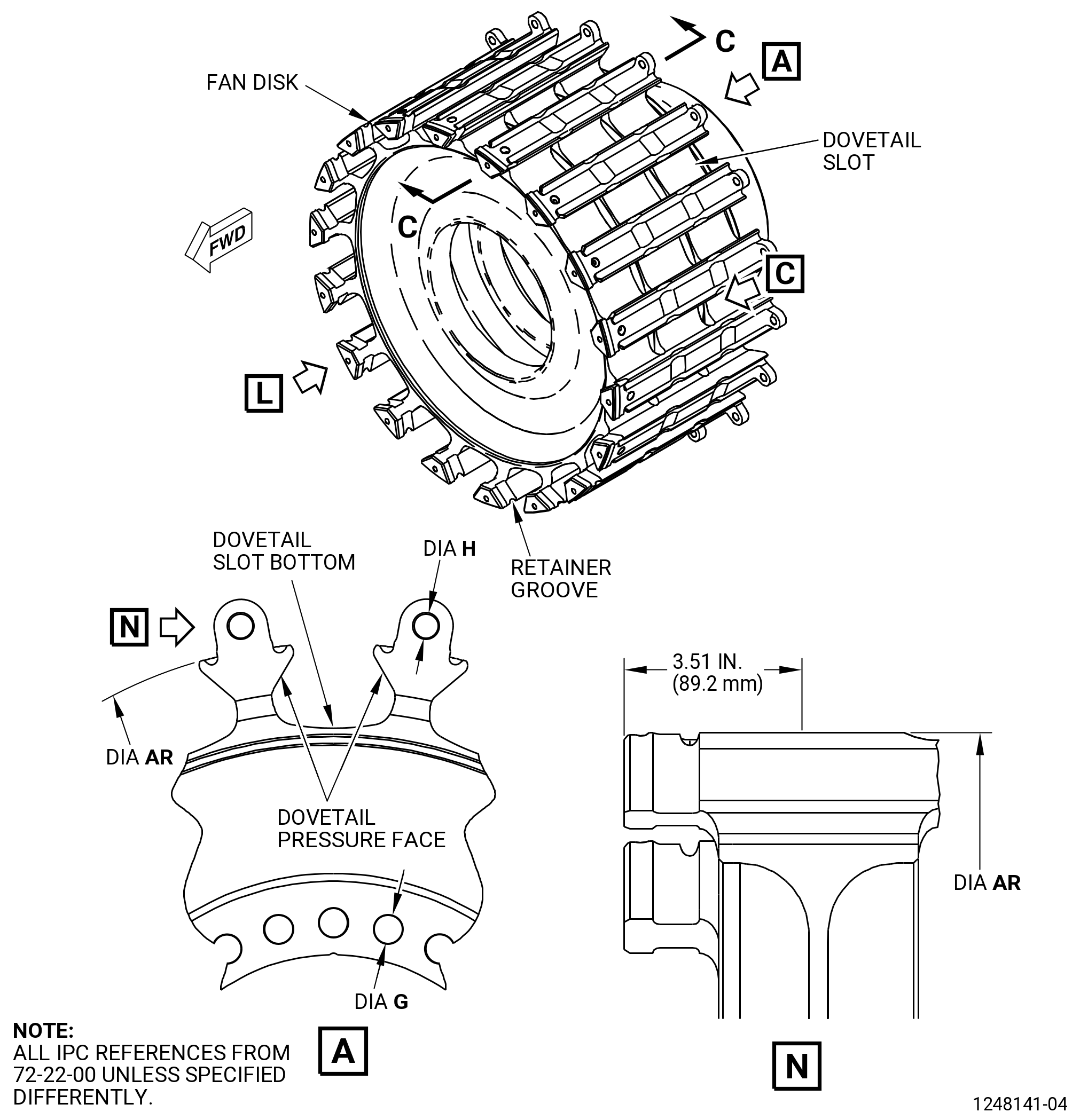
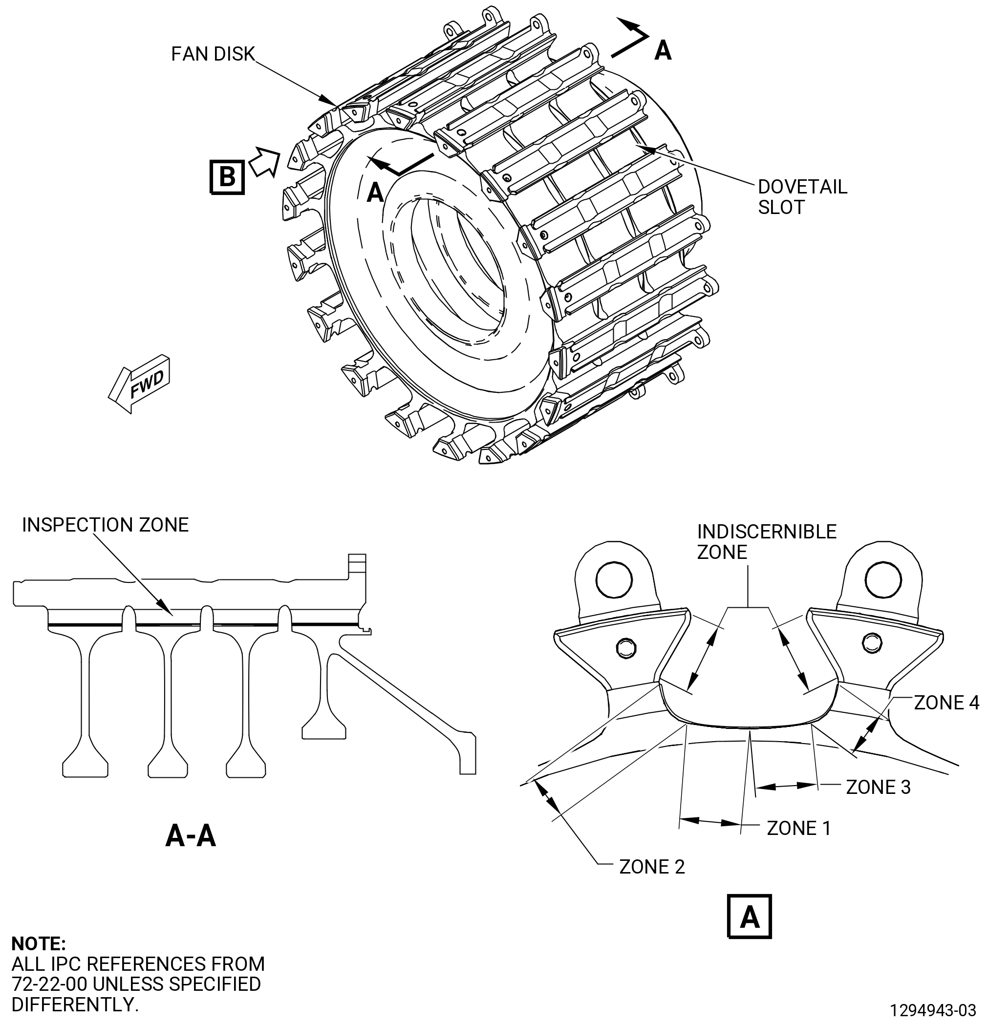
| A. | This procedure gives instructions to do an inspection of the fan rotor disk (fan disk). Refer to Figure 801. |
| • |
|
| • |
|
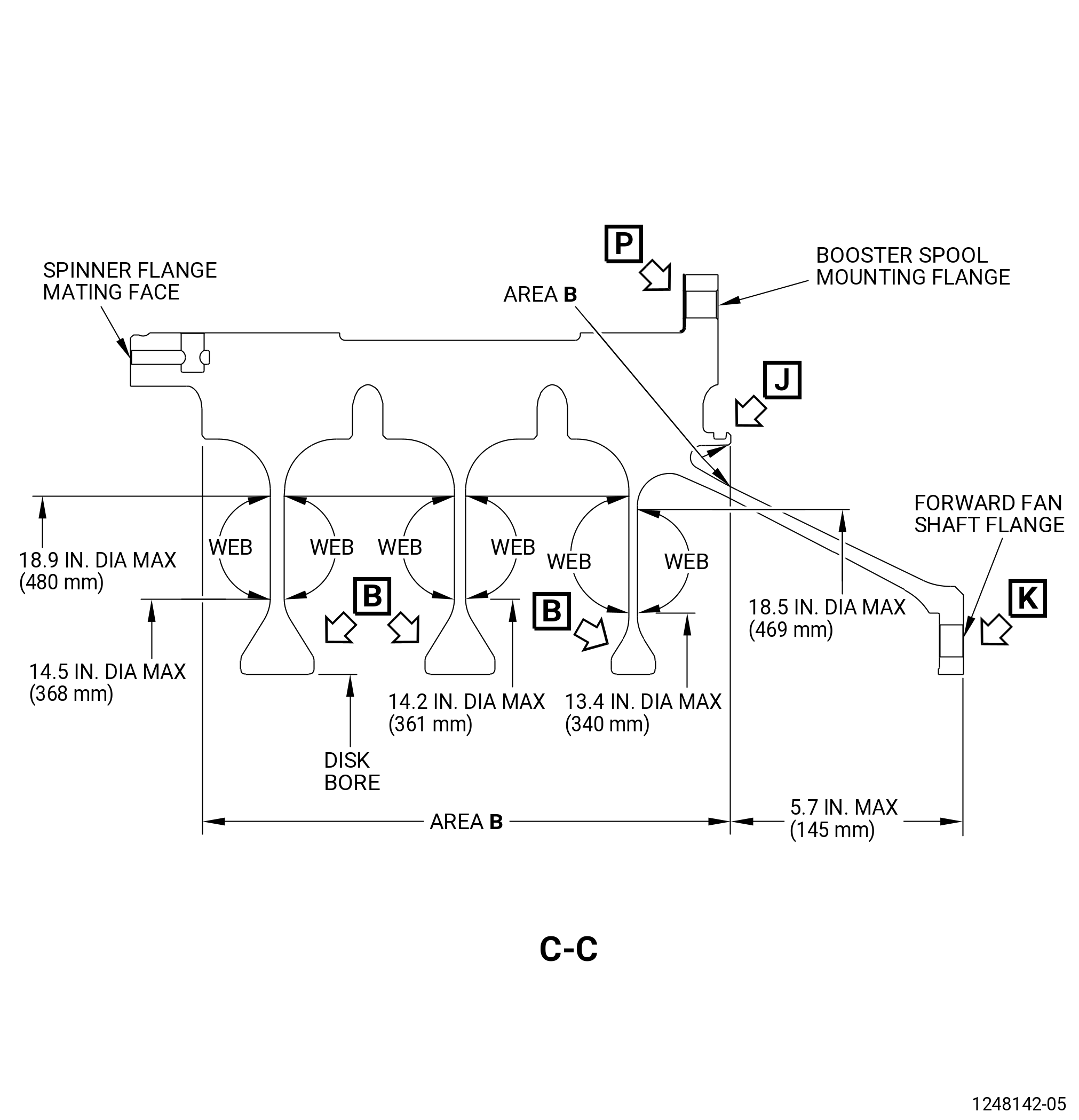
| B. | Critical areas that have an effect on part life are the dovetail slots, webs, and bores. |
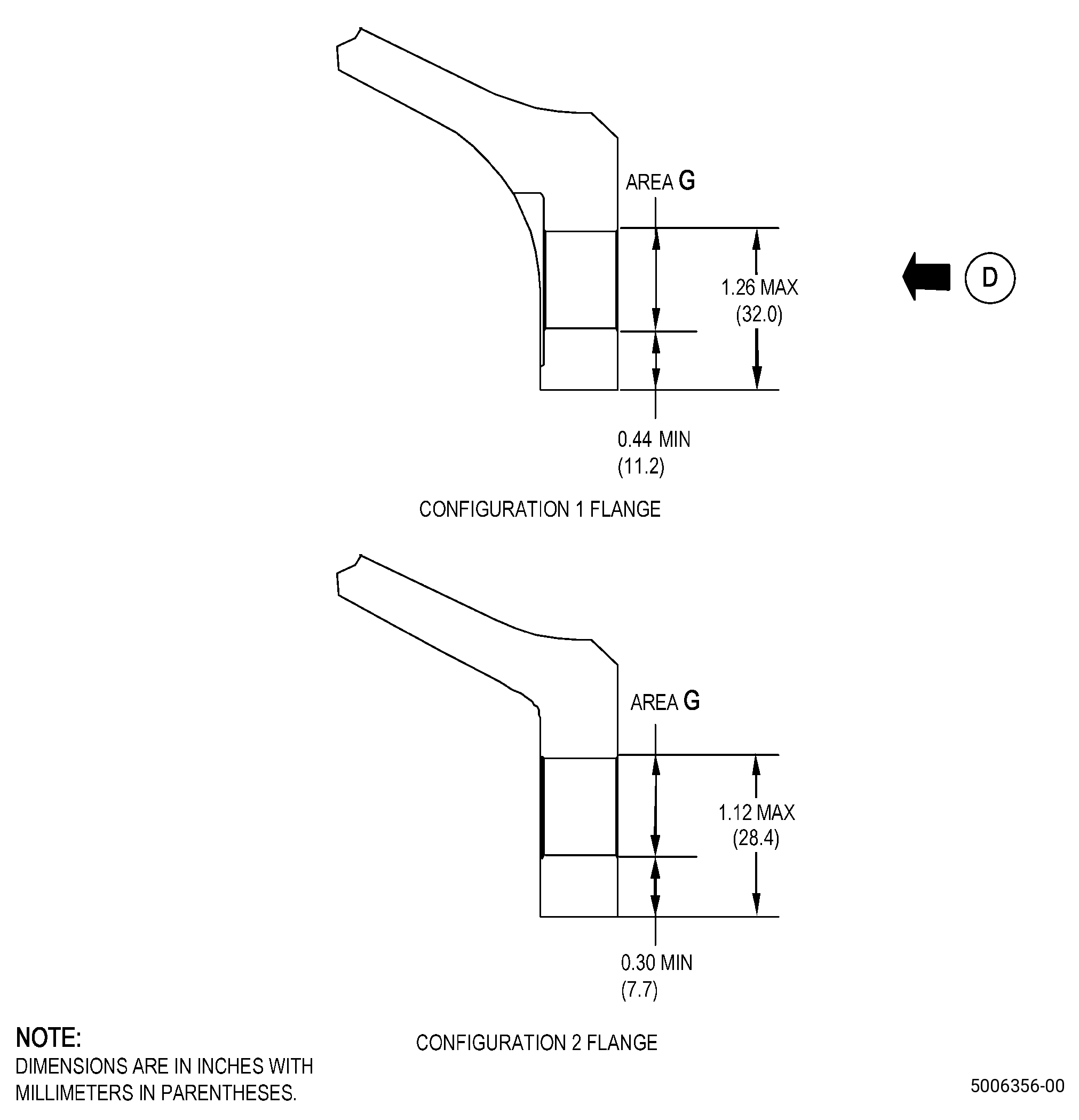
| C. | There are two configurations for the fan disk. The difference is in the forward fan shaft mounting flange. The configuration 1 fan disk contains counterbores (spot faces) on the forward side of the flange. The configuration 2 fan disk does not contain counterbores (spot faces) on the forward side of the flange. |
| 2 . | Tools, Equipment, and Materials. |
| NOTE: |
|
| A. | Tools and Equipment. |
| (1) | Special Tools. None. |
| (2) | Standard Tools and Equipment. |
| (3) | Locally Manufactured Tools. |
|
| B. | Consumable Materials. None. |
| C. | Referenced Procedures. |
|
| D. | Expendable Parts. None. |
| 3 . | Specific Inspection Procedure. |
| NOTE: |
|
| Subtask 72-22-40-110-005 |
| WARNING: |
|
| A. | Do a Class B etch of the pressure faces and bottoms of the slots of the dovetails. Refer to TASK 70-24-01-110-034 (SWAB ETCHING PROCEDURE) . |
| Subtask 72-22-40-230-001 |
| B. | Do a Class G fluorescent penetrant inspection of the fan disk. Refer to TASK 70-32-02-230-001 (FLUORESCENT PENETRANT INSPECTION). Use non-aqueous wet developer in the dovetail slots. |
| (1) | Make sure that you do an inspection of the critical areas that follow: |
| • |
|
| • |
|
| • |
|
| • |
|
| • |
|
| • |
|
| (2) | Indications larger than 0.015 inch (0.38 mm) are not permitted. |
| Subtask 72-22-40-160-003 |
| C. | Do an eddy current inspection of the fan disk bore surfaces as follows: |
| CAUTION: |
|
| (1) | Make sure that the fan disk is clean. Refer to TASK 72-22-40-100-801 (72-22-40, Cleaning 001). |
| Subtask 72-22-40-250-001 |
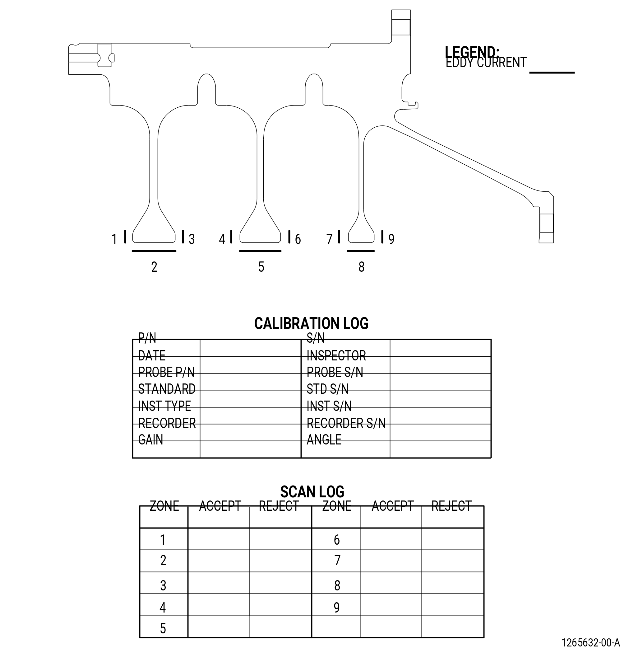
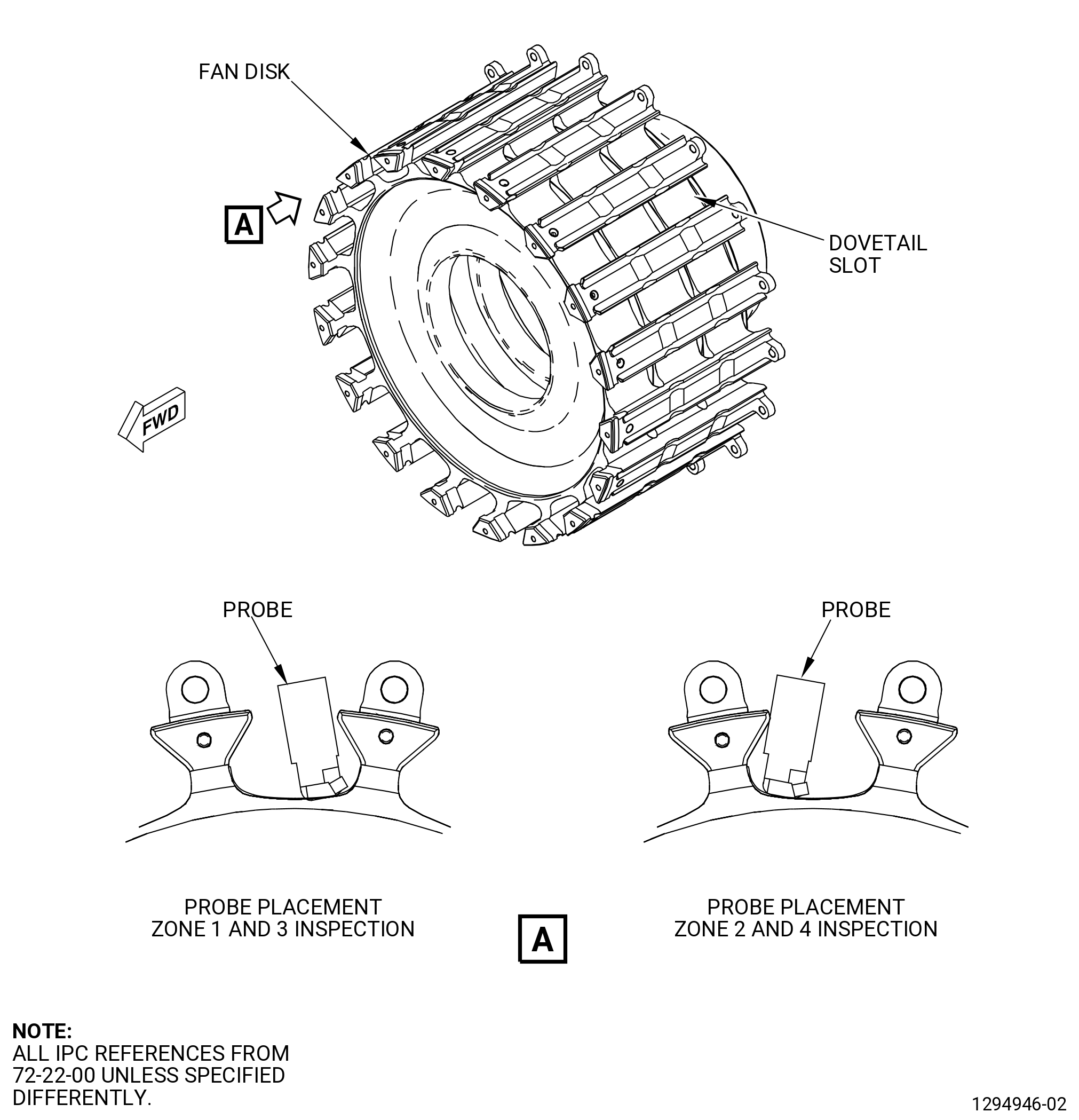
| (2) | Do an eddy current inspection of the bore surfaces. Refer to TASK 70-32-10-250-003 (2 MHZ EDDY CURRENT INSPECTION OF BORES IN ROTATING ENGINE HARDWARE USING SYSTEMS UNDER COMPUTER, NUMERIC, OR ROBOTIC CONTROL) and Figure 802. |
| NOTE: |
|
| (a) | If you change the equipment or the procedure specified in this inspection, it can have an unwanted effect on the inspection results. Before you change the equipment or the procedure, write to: |
| GE Aviation |
| Field Support Technology |
| One Neumann Way, MD: Q8 |
| Cincinnati, Ohio 45215 USA |
| (b) | The material is Titanium. Use correction factors for calibration as necessary. Refer to TASK 70-32-10-250-003 (2 MHZ EDDY CURRENT INSPECTION OF BORES IN ROTATING ENGINE HARDWARE USING SYSTEMS UNDER COMPUTER, NUMERIC, OR ROBOTIC CONTROL). |
| (c) | Use the GE-FQAP-428inspection kit to do an inspection of the bore zones shown in Figure 802. |
| (d) | Examine the inspection results. Use the limits that follow: |
| 1 | The eddy current inspection limit is 1500 mV. |
| 2 | If the amplitude of an indication is more than 1500 mV, the fan disk is not serviceable. |
| (e) | Complete the eddy current data sheets. |
| (f) | Make sure you complete all records during the eddy current inspection. Keep all records made during the inspection. |
| Subtask 72-22-40-270-009 |
| D. | Do an ultrasonic inspection of the fan disk dovetail slots. Refer to TASK 70-32-06-270-001 (ULTRASONIC INSPECTION) . |
| NOTE: |
|
| NOTE: |
|
| (1) | Personnel Requirements: |
| (a) | Personnel performing this inspection must be certified in accordance with NAS-410, American Society of Nondestructive Testing (ASNT-TC-1A), Air Transport Association Specification No. 105 (ATA 105), COSAC, or any equivalent certification document acknowledged by the local regulatory agencies. |
| (b) | It is strongly recommended that personnel performing this inspection receive practical training in the use of this procedure and must demonstrate proficiency in the calibration, inspection, and evaluation routines before accept/reject authority is delegated. |
| (c) | Any training which may be provided regarding the performance of this inspection does not imply that the personnel who receive that training have met the requirements for inspector certification in accordance with the appropriate certification document. |
| Subtask 72-22-40-160-007 |
| (2) | Pre-Inspection Preparation: |
| CAUTION: |
|
| (a) | Visually inspect each dovetail slot and assure test area is clean, dry, and free of any contaminants that may interfere with inspection. |
| (b) | If necessary, clean the fan disk dovetail slots. Refer to TASK 72-22-40-100-801 (72-22-40, Cleaning 001). |
| (c) | Locate the serial number (S/N) on the forward end of the disk, the “/” in S/N is the 12 o’clock position aft looking forward (ALF). Number each slot clockwise, forward looking aft (FLA), for reference purposes. |
| Subtask 72-22-40-820-001 |
| (3) | Initial equipment setup: |
| NOTE: |
|
| (a) | Connect the ultrasonic instrument to the appropriate power source and switch the instrument power on. Allow the instrument to warm up for at least 10 minutes or the manufacturer’s recommended warm up time. |
| (b) | Connect the probe to the ultrasonic instrument. |
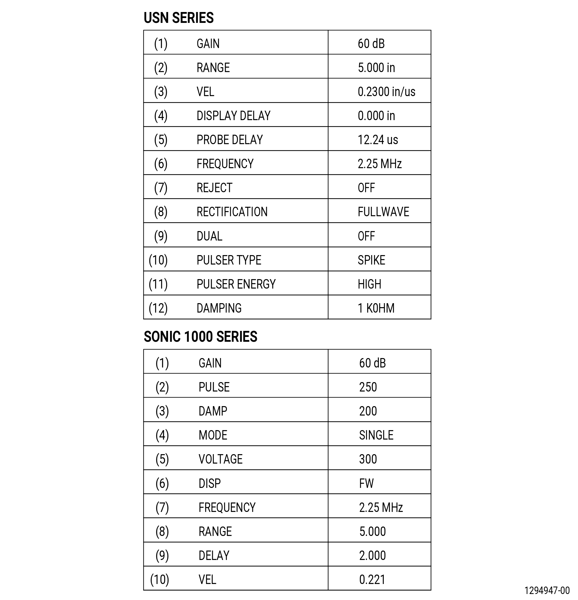
| (c) | Adjust the ultrasonic instrument to the basic settings in Figure 804. |
| (d) | Use delay control only, locate the signal from the transducer wedge and position the signal on the 0.0 division on the cathode ray tube (CRT). |
| Subtask 72-22-40-820-002 |
| (4) | Equipment Calibration: |
| (a) | Prepare ultrasonic instrument and probe according to Subtask 72-22-40-820-001 (paragraph 3.D.(3)). |
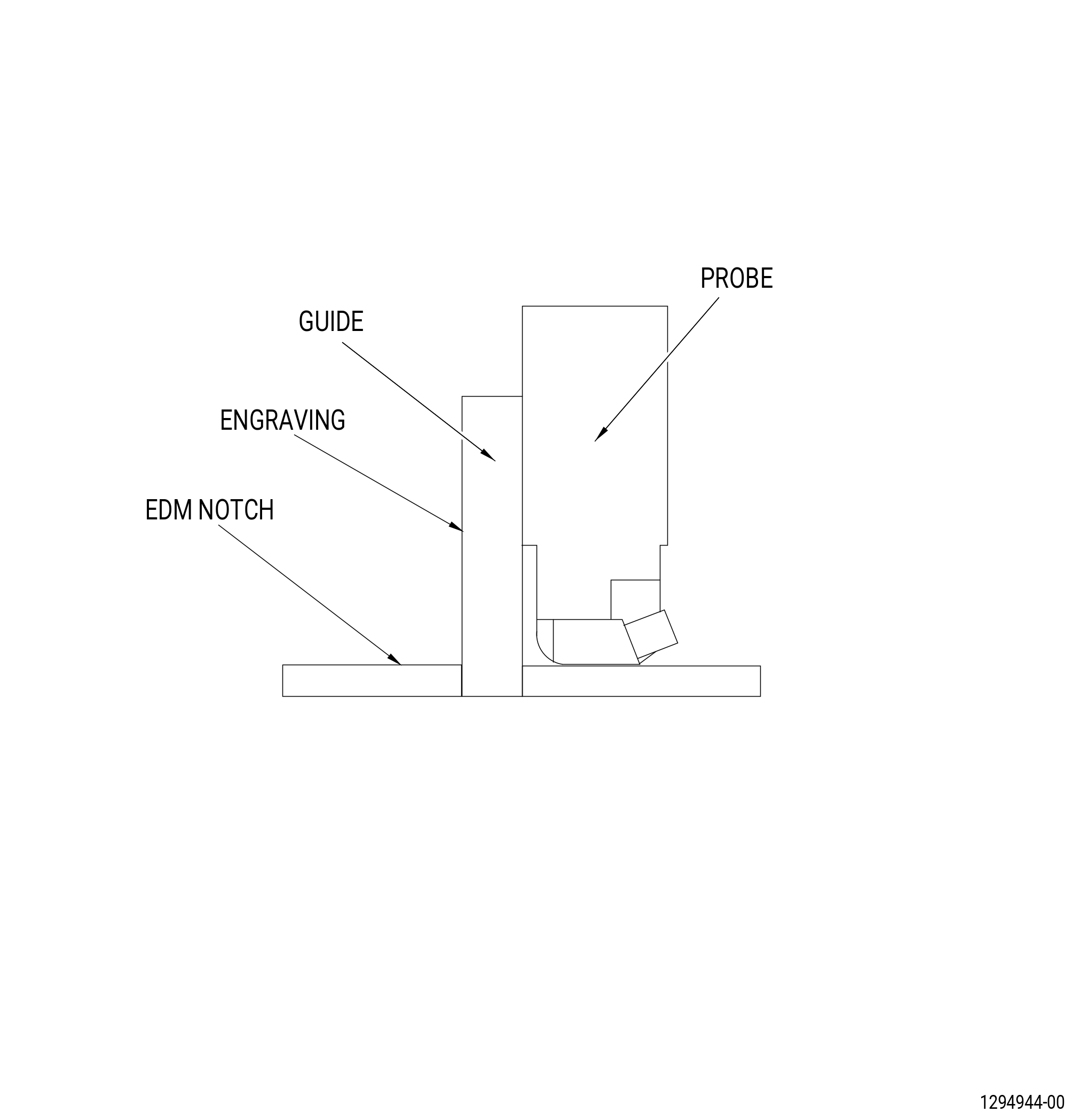
| (b) | Refer to Figure 805 and Figure 806 for calibration. |
| (c) | Apply a small amount of couplant to the standard and visually make sure that there will be no excess couplant in front of the transducer. |
| (d) | Put the probe on the standard as shown in Figure 805 and make sure that the flat side of the probe is flat against the guide. |
| NOTE: |
|
| (e) | Slide the probe across the standard and locate the response from the EDM notch. Adjust the instrument gain so that the amplitude of the response is approximately 80 percent of full screen height (FSH). |
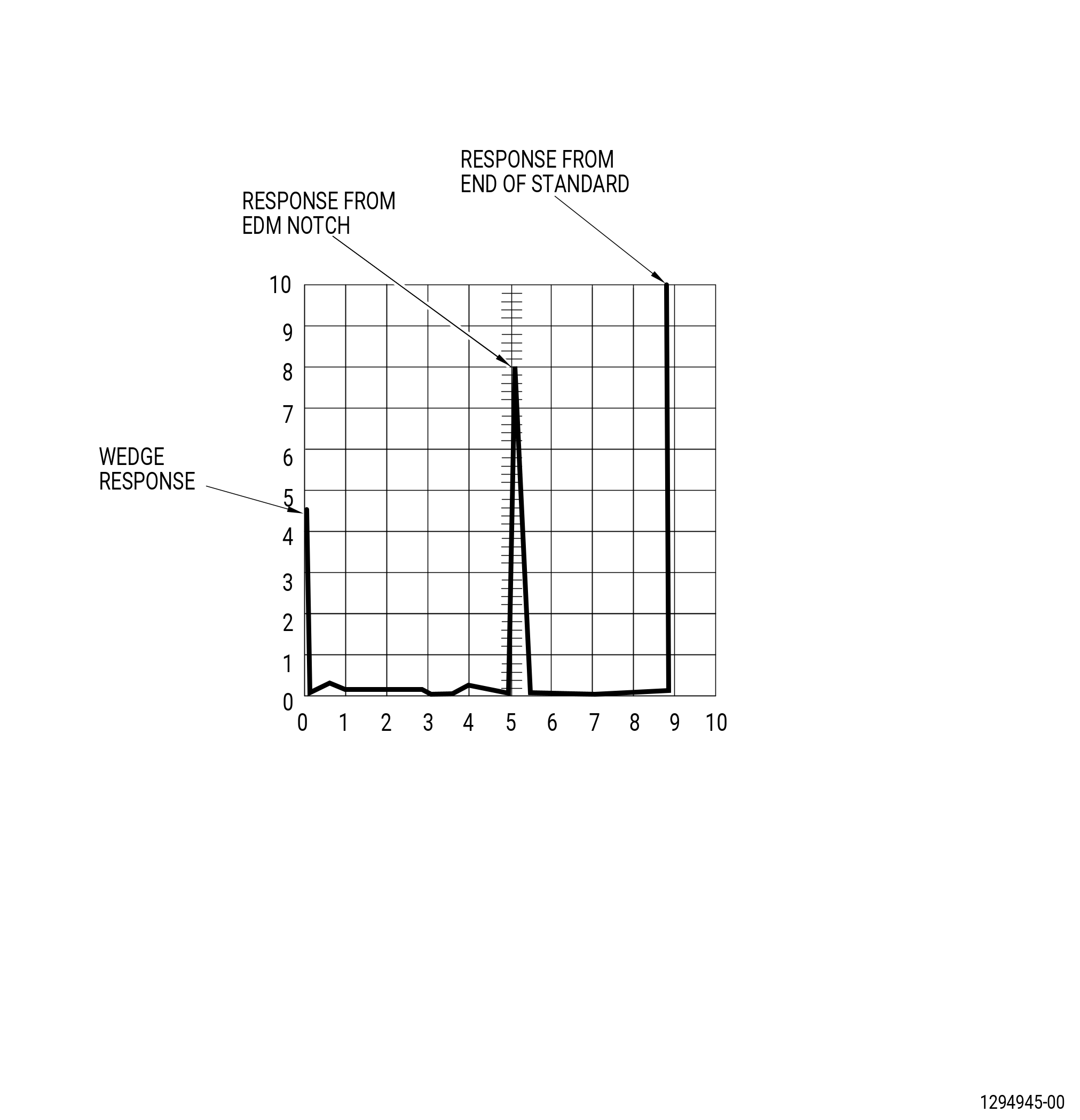
| (f) | Adjust range and delay so that the trailing edge of the transducer wedge signal is at 0.0 on the CRT base line and the leading edge of the response from the notch is at the 5.0 on the CRT baseline. |
| (g) | Record range and delay settings. |
| (h) | Slide the probe along the standard and make sure that the flat side of the probe is flat against the guide. Maximize the response from the EDM notch. Adjust the gain to set the amplitude of the response to 80 percent FSH. |
| (i) | Final screen presentation should be similar to Figure 806. |
| (j) | Record the gain. |
| Subtask 72-22-40-270-010 |
| (5) | Inspection: |
| NOTE: |
|
| (a) | Refer to Figure 807 for inspection details. |
| (b) | Make sure that pre-inspection preparation, initial equipment set-up, and system calibration for the area to be inspected are complete according to sections Subtask 72-22-40-820-001 (paragraph 3.D.(3)), Subtask 72-22-40-820-002 (paragraph 3.D.(4)), and Subtask 72-22-40-270-010 (paragraph 3.D.(5)). |
| (c) | Apply couplant to the dovetail for the inspection of zone 1 and visually make sure that there will be no excess couplant in front of the transducer. |
| (d) | Place the probe in the dovetail slot as shown in Figure 807 for inspection of zone 1. |
| (e) | Gate from 0.5 to 7.0 on the CRT baseline. |
| (f) | Slide the probe down the dovetail slot while you monitor the CRT. |
| (g) | Evaluate all indications greater than or equal to 50 percent of FSH. Refer to Subtask 72-22-40-270-011 (paragraph 3.D.(7)). |
| (h) | Repeat Subtask 72-22-40-270-010 (paragraph 3.D.(5)(c)) through Subtask 72-22-40-270-010 (paragraph 3.D.(5)(g)) for each dovetail slot for the inspection of zone 1. |
| (i) | Apply couplant to the dovetail for the inspection of zone 2 and visually make sure that there will be no excess couplant in front of the transducer. |
| (j) | Place the probe in the dovetail slot as shown in Figure 807 for inspection of zone 2. |
| (k) | Gate from 0.5 to 6.0 on the CRT baseline. |
| (l) | Slide the probe down the dovetail slot while observing the CRT. |
| (m) | Evaluate all indications greater than or equal to 50 percent of FSH. Refer to Subtask 72-22-40-270-011 (paragraph 3.D.(7)). |
| (n) | Repeat Subtask 72-22-40-270-010 (paragraph 3.D.(5)(i)) thru Subtask 72-22-40-270-010 (paragraph 3.D.(5)(m)) for each dovetail slot for the inspection of zone 2. |
| (o) | Use an approved solvent, clean each dovetail slot to remove couplant. |
| (p) | Repeat Subtask 72-22-40-270-010 (paragraph 3.D.(5)(c)) thru Subtask 72-22-40-270-010 (paragraph 3.D.(5)(n)) with the probe facing the opposite direction for the inspection of zone 3 and zone 4. |
| Subtask 72-22-40-820-003 |
| (6) | Calibration Check: |
| (a) | A calibration check must be performed after inspection. Also, check calibration whenever any system component or operator is changed, after any loss of power, and at any time the operator suspects a change in the system. |
| (b) | If the amplitude of the response from the EDM notch has increased by more than 15 percent FSH above the calibration amplitude, the system must be recalibrated before the inspection of additional hardware. It will be necessary to re-inspect any rejected hardware examined since the last acceptable calibration once correct calibration has been achieved. |
| (c) | If the amplitude of the response from the EDM notch has decreased by more than 15 percent FSH below the calibration amplitude, the system must be recalibrated and all hardware inspected since the last acceptable calibration or calibration check must be re-inspected. |
| Subtask 72-22-40-270-011 |
| (7) | Indication Evaluation: |
| (a) | Any indication(s) that equals or exceeds 50 percent FSH must be evaluated as follows: |
| 1 | Check calibration to verify it is acceptable. Refer to Subtask 72-22-40-820-002 (paragraph 3.D.(4)). Re-inspect the area to verify that the signal is repeatable. If the indication does not exceed 50 percent then the indication is acceptable, if the indication exceeds 50 percent proceed as follows: |
| a | Perform a visual inspection on the dovetail slot for any surface defects and geometry changes that could cause indications. |
| b | If the signal repeats, clean area with approved solvents and then re-inspect. |
| c | If the signal repeats, do Subtask 72-22-40-110-005 (paragraph 3.A.) and Subtask 72-22-40-230-001 (paragraph 3.B.) again in the specific area of indication. |
| d | If the signal equals or exceeds 50 percent FSH, and is outside of zone 2 and 4 as referenced in Figure 803, view B, then this area is indiscernible and the disk is rejectable. |
| e | Record the results on the data sheet Form 2032-1. Reference indication location by dovetail number and axial position from the forward end of the slot and provide to GE for review. |
| f | If the signal equals or exceeds 50 percent FSH in any zone 1-4, the disk is rejectable. |
| g | Record the results on the data sheet Form 2032-1. Reference indication location by dovetail number and axial position from the forward end of the slot and provide to GE for review. |
| Subtask 72-22-40-270-012 |
| (8) | Documentation: |
| (a) | All calibration and inspection data must be recorded on the appropriate operator logs (2032-1). Refer to Figure 808. |
| (b) | Document all inspection results on the operator logs. |
| (c) | It is the inspection facilities responsibility to maintain all inspection records. The inspection records should be maintained with the permanent record of the part and must be maintained for the life of the part. |
| 4 . | Visual Inspection. |
| Refer to Figure 801. |
| Subtask 72-22-40-220-003 |
| A. | Do an inspection of all areas of the fan disk for: |
| (1) | Cracks: |
| Maximum serviceable limit: |
|
| Repair method: |
|
| Subtask 72-22-40-220-017 |
| (2) | Discoloration that is a result of a shotpeen procedure (rust color): |
| Maximum serviceable limit: |
|
| Repair method: |
|
| Subtask 72-22-40-220-018 |
| (3) | Nicks, dents, and scratches (all areas unless identified in other paragraphs): |
| Maximum serviceable limit: |
|
| Maximum repairable limit: |
|
| Repair method: |
|
| Subtask 72-22-40-220-004 |
| (4) | Nicks, dents, and scratches in the web areas: |
| Maximum serviceable limit: |
|
| Maximum repairable limit: |
|
| Repair method: |
|
| Subtask 72-22-40-220-005 |
| (5) | Nicks, dents, scratches, and fretting (on the seal aft face only): |
| Maximum serviceable limit: |
|
| Repair method: |
|
| Subtask 72-22-40-220-019 |
| (6) | Nicks, dents, scratches, and fretting (in the retainer grooves only): |
| Maximum serviceable limit: |
|
| Repair method: |
|
| Subtask 72-22-40-220-020 |
| (7) | Nicks, dents, scratches, and fretting (on the seal aft face, surface D, and surface E only): |
| Maximum serviceable limit: |
|
| Maximum repairable limit: |
|
| Repair method: |
|
| Subtask 72-22-40-220-036 |
| (8) | Gouges on the seal aft face, surface D, and surface E: |
| Maximum serviceable limit: |
|
| Repair method: |
|
| Subtask 72-22-40-220-030 |
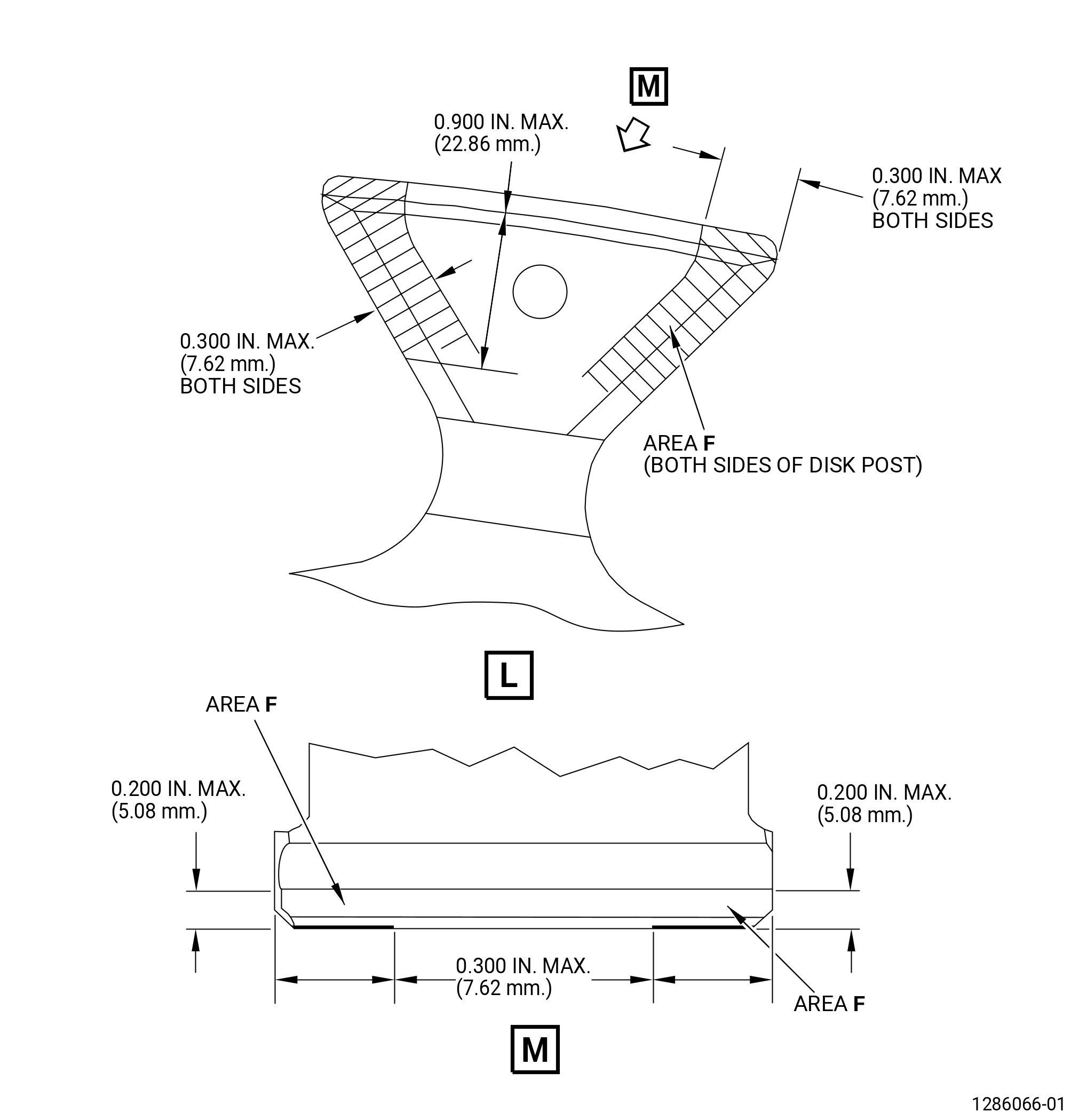
| (9) | Nicks, dents, and scratches (on the spinner aft support ring flange mating face chamfer (area F)): |
| Maximum serviceable limit: |
|
| Repair method: |
|
| Subtask 72-22-40-220-037 |
| (10) | Nicks, dents, and scratches in area B (do not include the web areas). Refer to Figure 801. |
| Maximum serviceable limit: |
|
| Repair method: |
|
| Subtask 72-22-40-220-042 |
| (11) | Nicks, dents, and scratches in area B bores. Refer to Figure 801. |
| Maximum serviceable limit: |
|
| Repair method: |
|
| Subtask 72-22-40-220-006 |
| B. | Do an inspection of the boltholes on the fan disk for: |
| (1) | Cracks: |
| Maximum serviceable limit: |
|
| Repair method: |
|
| Subtask 72-22-40-220-021 |
| (2) | Nicks, dents, and scratches: |
| Maximum serviceable limit: |
|
| Maximum repairable limit: |
|
| Repair method: |
|
| Subtask 72-22-40-220-038 |
| (3) | Galling: |
| Maximum serviceable limit: |
|
| Repair method: |
|
| Subtask 72-22-40-220-007 |
| C. | Do an inspection of the dovetail slots for: |
| (1) | Nicks, dents, scratches, and fretting on the pressure faces: |
| Maximum serviceable limit: |
|
| Repair method: |
|
| Subtask 72-22-40-220-022 |
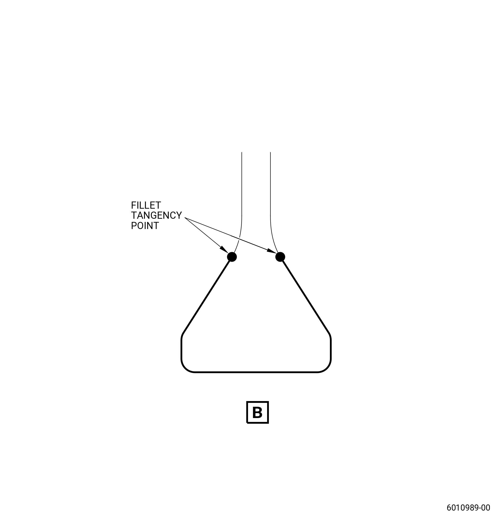
| (2) | Nicks, dents, scratches, and fretting on the radius below and adjacent to the pressure faces: |
| Maximum serviceable limit: |
|
| Repair method: |
|
| Subtask 72-22-40-220-023 |
| (3) | Nicks, dents, scratches, and fretting on the bottom of the slots: |
| Maximum serviceable limit: |
|
| Repair method: |
|
| Subtask 72-22-40-220-043 |
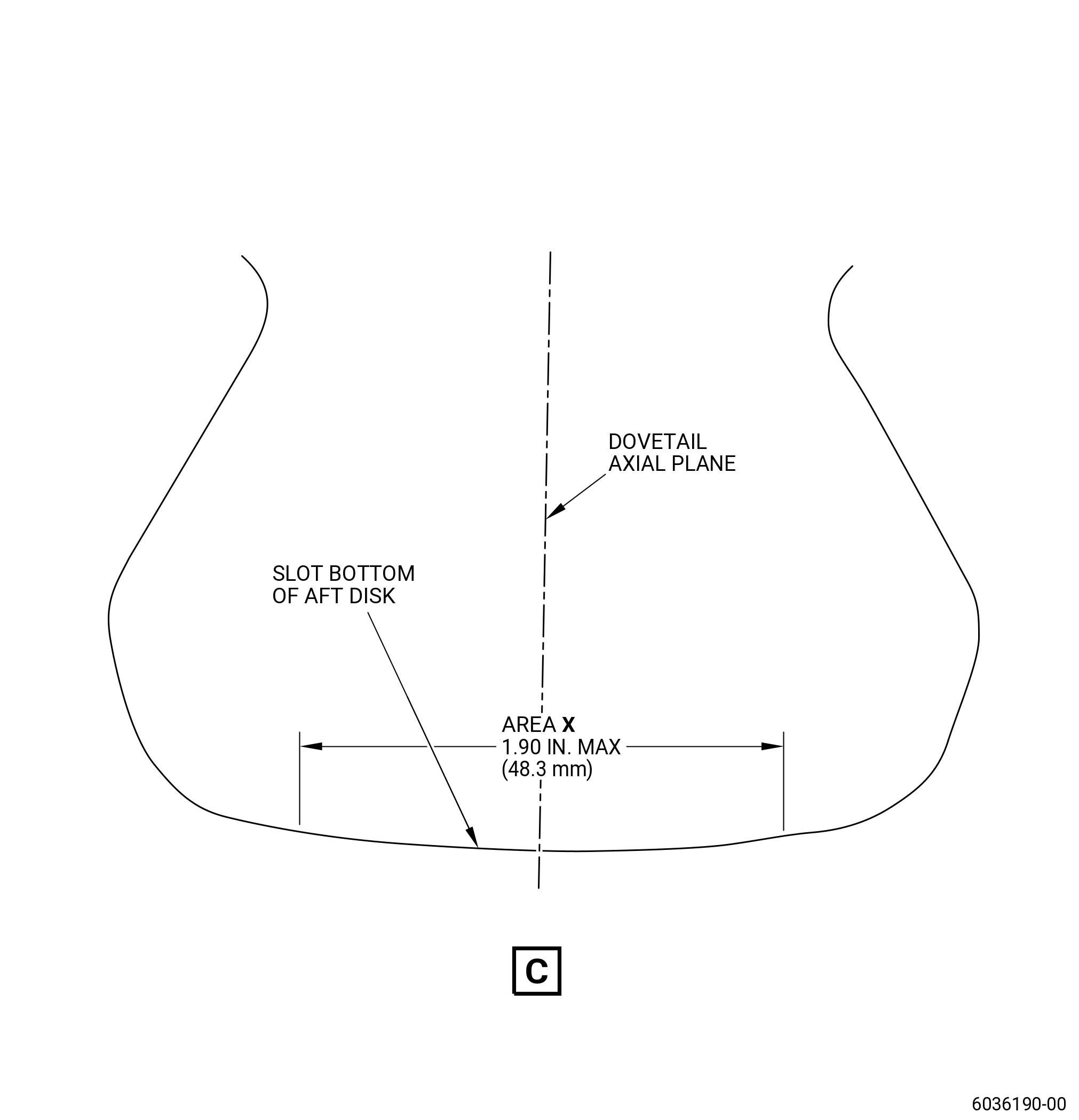
| (4) | Wear/fretting on the bottom of the dovetail slots aft disk because of contact with the dovetail key (20-180 , 72-00-00) (SIN 8300B): |
| Maximum serviceable limit: |
|
| Repair method: |
|
| Subtask 72-22-40-220-024 |
| (5) | Nicks, dents, and scratches on the corners of the leading and trailing edges of the dovetail: |
| Maximum serviceable limit: |
|
| Repair method: |
|
| Subtask 72-22-40-220-008 |
| D. | Do an inspection of the forward and aft surfaces of the booster spool mounting flange, the flange of the forward fan shaft, and the spinner flange mating face for: |
| (1) | Cracks: |
| Maximum serviceable limit: |
|
| Repair method: |
|
| Subtask 72-22-40-220-032 |
| (2) | Nicks, dents, and scratches in area V. Refer to Figure 801. |
| Maximum serviceable limit: |
|
| Maximum repairable limit: |
|
| Repair method: |
|
| Subtask 72-22-40-220-034 |
| (3) | Nicks, dents, and scratches on the forward face of the posts (area F not included): |
| Maximum serviceable limit: |
|
| Maximum repairable limit: |
|
| Repair method: |
|
| Subtask 72-22-40-220-025 |
| (4) | Nicks, dents, and scratches (all other locations): |
| Maximum serviceable limit: |
|
| Repair method: |
|
| Subtask 72-22-40-220-009 |
| (5) | Fretting: |
| Maximum serviceable limit: |
|
| Repair method: |
|
| Subtask 72-22-40-220-010 |
| (6) | Rub marks on the booster spool mounting flange from contact with the balance weights: |
| Maximum serviceable limit: |
|
| Repair method: |
|
| Subtask 72-22-40-220-041 |
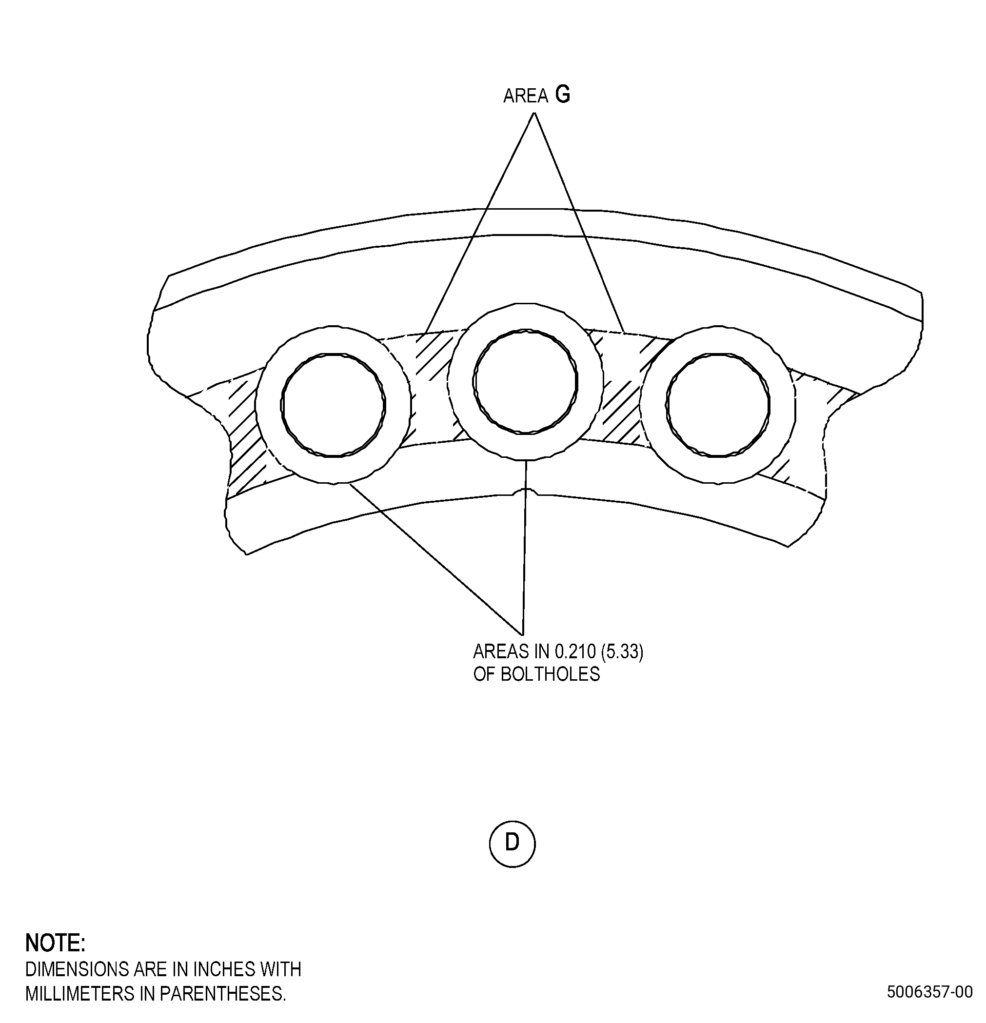
| (7) | Nicks, dents, scratches, and fretting on the forward and aft surfaces of forward fan shaft mounting flange in 0.210 inch (5.33 mm) of the boltholes: |
| Maximum serviceable limit: |
|
| Repair method: |
|
| Subtask 72-22-40-220-039 |
| (8) | Nicks, dents, scratches, and fretting in area G. Refer to Figure 801. |
| Maximum serviceable limit: |
|
| Repair method: |
|
| Subtask 72-22-40-220-040 |
| (9) | Nicks, dents, scratches, and fretting on the forward and aft surfaces of the forward fan shaft mounting flange (but not in 0.210 inch (5.34 mm) of the boltholes and area G). |
| Maximum serviceable limit: |
|
| Repair method: |
|
| 5 . | Dimensional Inspection. |
| Refer to Figure 801. |
| Subtask 72-22-40-220-011 |
| A. | Do an inspection of the diameters that follow: |
| (1) | Diameter G (shaft mounting flange bolthole): |
| Maximum serviceable limit: |
|
| NOTE: |
|
| Repair method: |
|
| Subtask 72-22-40-220-026 |
| (2) | Diameter H (booster spool mounting flange bolthole): |
| Maximum serviceable limit: |
|
| NOTE: |
|
| Repair method: |
|
| Subtask 72-22-40-220-027 |
| (3) | Diameter AR: |
| NOTE: |
|
| Minimum serviceable limit: |
|
| Maximum serviceable limit: |
|
| Repair method: |
|
| 6 . | Dovetail Slot Pressure Faces - Inspection. |
| Refer to Figure 809. |
| Subtask 72-22-40-930-001 |
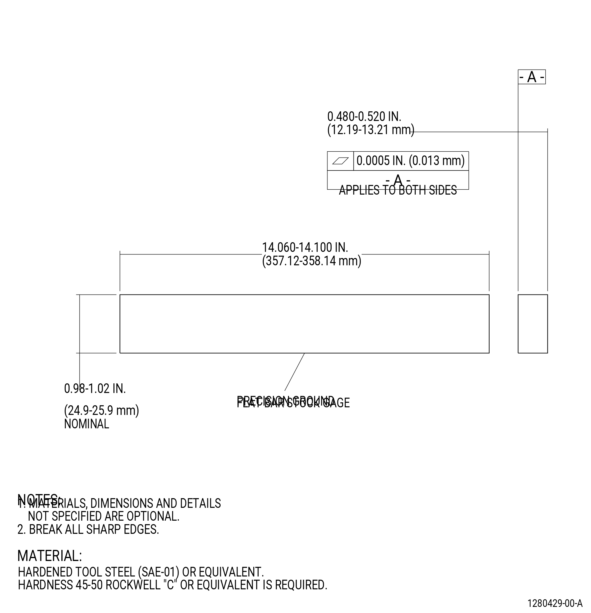
| A. | Make the Dovetail Pressure Face Inspection Gage (Inspection Gage). Refer to Figure 809. |
| Subtask 72-22-40-220-012 |
| B. | Do an inspection of the dovetail pressure faces as follows: |
| (1) | Use the inspection gage to do an inspection of the pressure faces in dovetail slot No. 1 as follows: |
| NOTE: |
|
| Subtask 72-22-40-220-013 |
| CAUTION: |
|
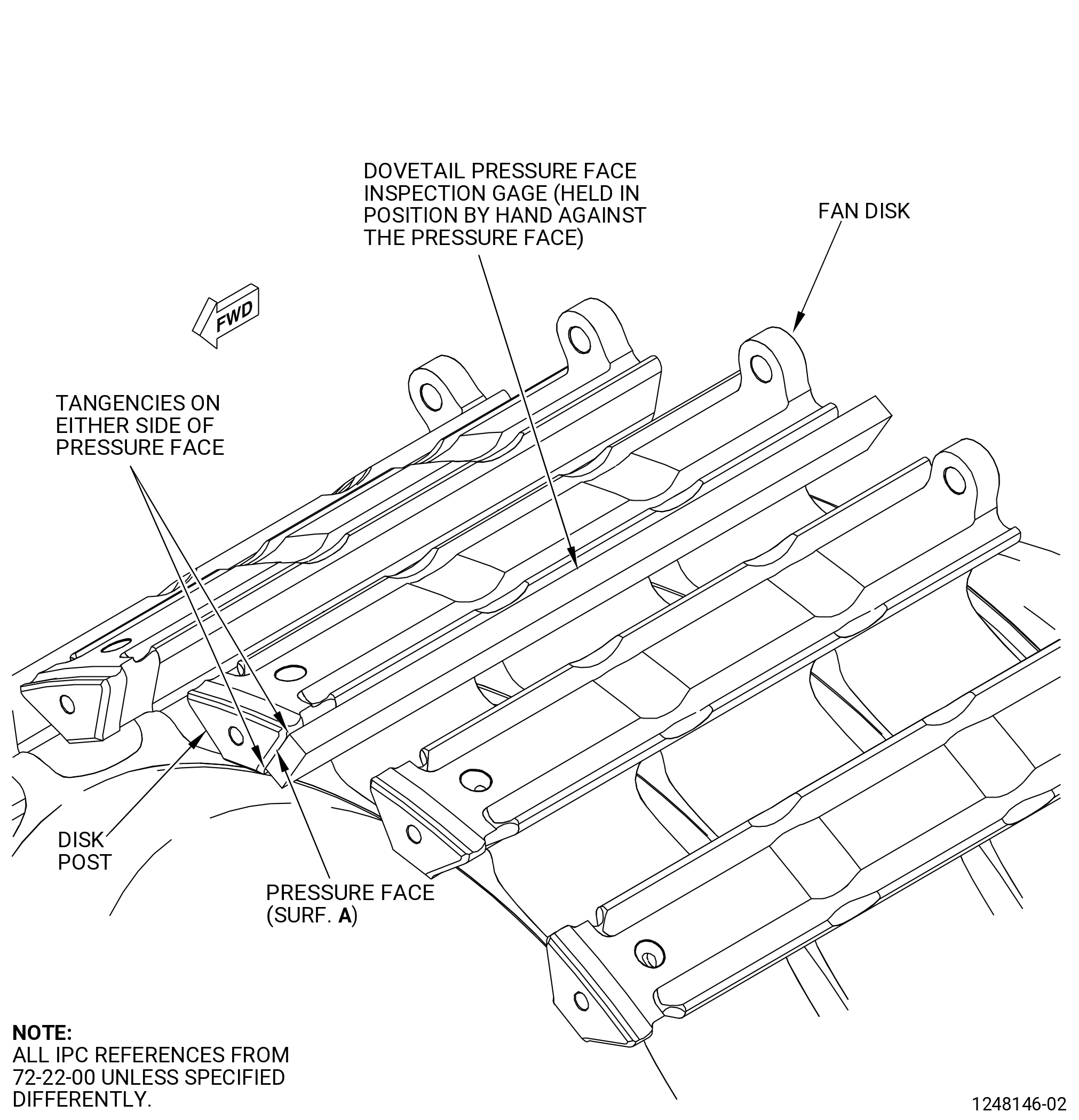
| (a) | Put the inspection gage in the dovetail slot and push surface A against the pressure face on one side of the slot. Make sure that surface A is between the tangency points. Refer to Figure 810. |
| (b) | Put a bright light behind the inspection gage. If the light shows between the inspection gage and the pressure face, measure the gap with a gage wire. |
| (c) | The fan disk is serviceable if the gap is not more than 0.0035 inch (0.089 mm). |
| (d) | The fan disk is repairable if the gap is not more than 0.010 inch (0.25 mm). |
| NOTE: |
|
| (e) | Do the procedure again on the pressure face on the other side of the slot. |
| Subtask 72-22-40-220-014 |
| (2) | Do the procedure again for each dovetail slot. Refer to Subtask 72-22-40-220-013 (paragraph 6.B.(1)(a)). |