|
Add note for the illustration of 11C3166 at subtask 72-00-23-020-009 |
| GENX-1B ENGINE MANUAL | Dated: 02/23/2021 | |
| EM 72-00-23 , REMOVAL 001 | ||
| NO. 1 BEARING ASSEMBLY - REMOVAL 001 | ||
|
Add note for the illustration of 11C3166 at subtask 72-00-23-020-009 |
| GENX-1B ENGINE MANUAL | Dated: 02/23/2021 | |
| EM 72-00-23 , REMOVAL 001 | ||
| NO. 1 BEARING ASSEMBLY - REMOVAL 001 | ||
| * * * FOR ALL |
| TASK 72-00-23-020-801 |
| 1 . | General. |
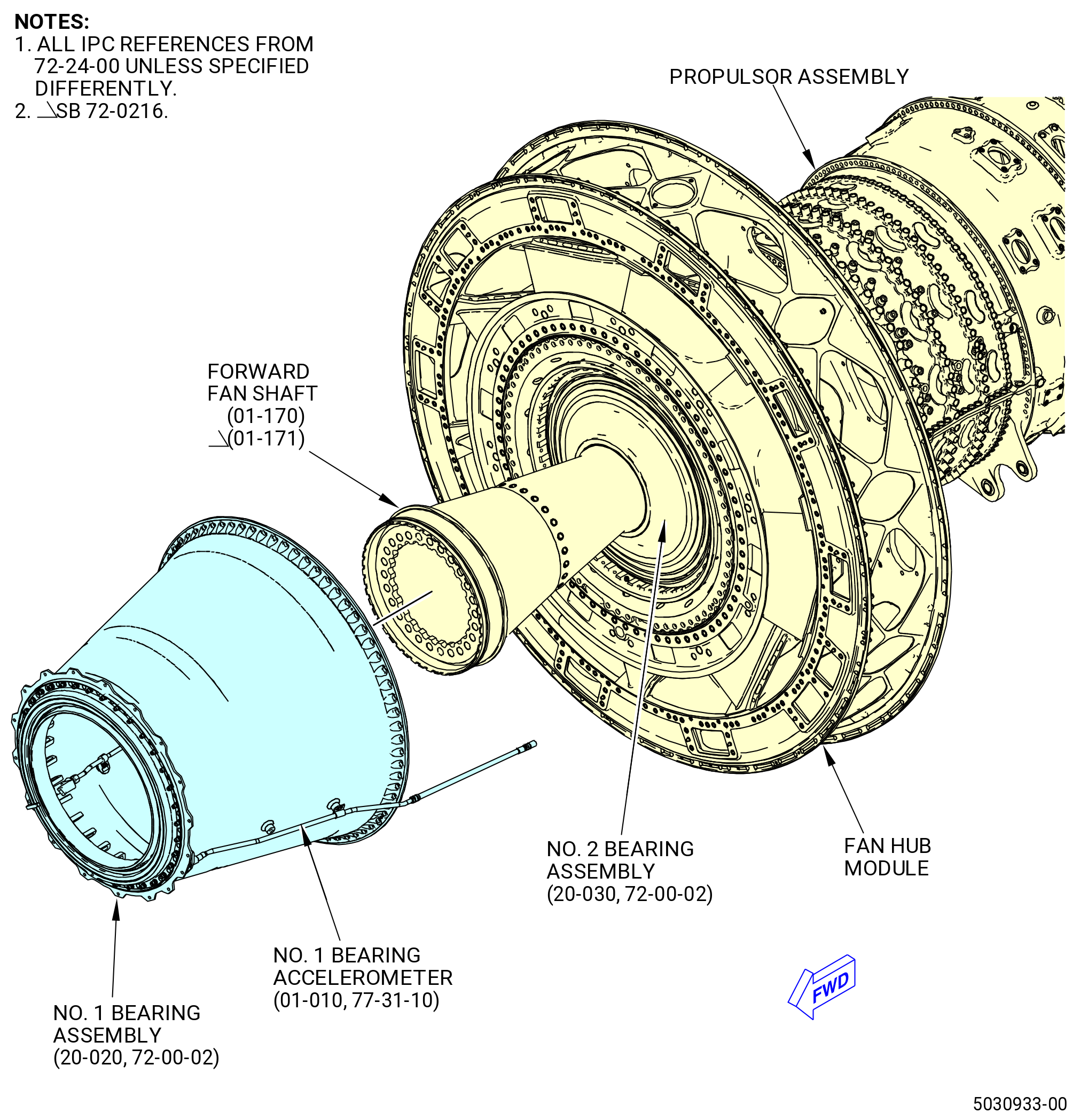
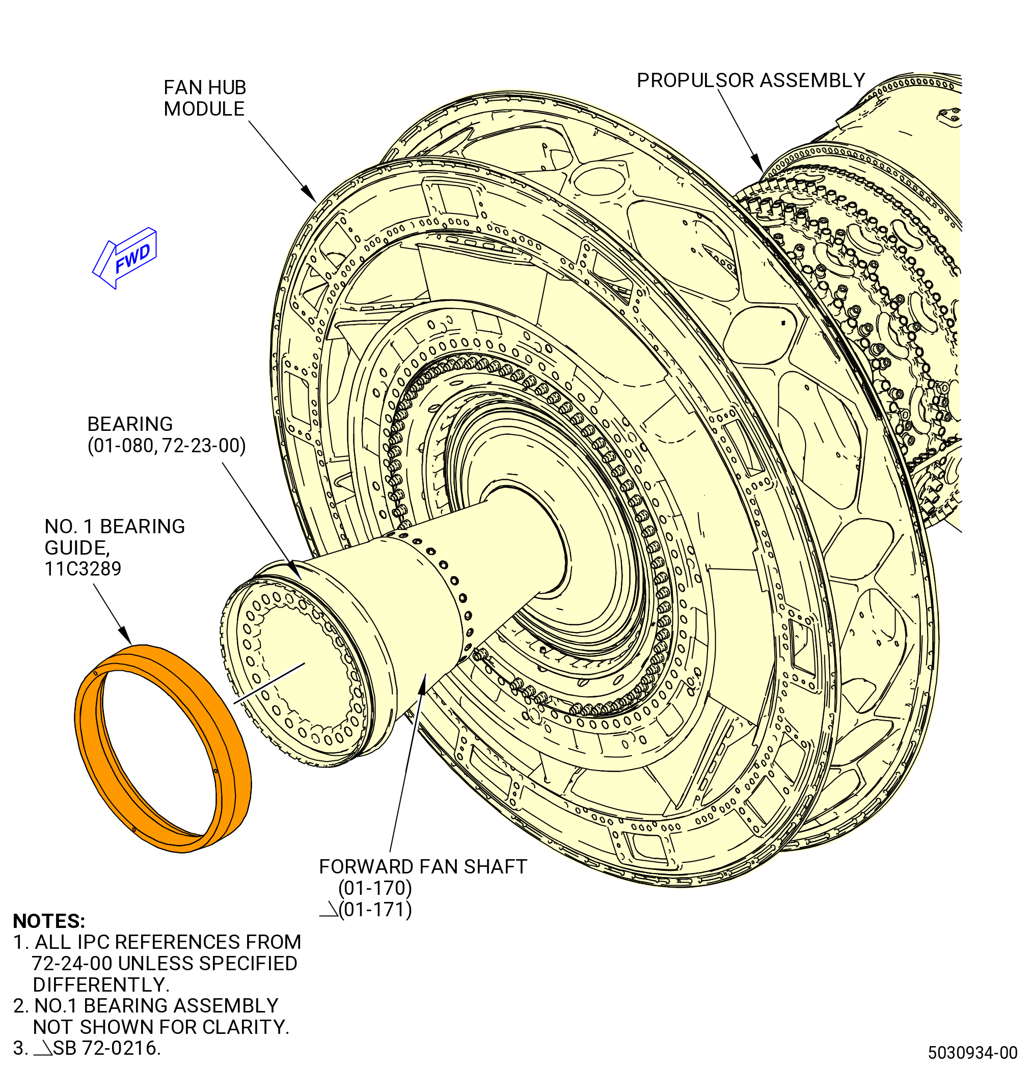
| A. | This procedure gives instructions to remove the No. 1 bearing assembly (01100). Refer to Figure 301. |
| B. | This procedure starts with the propulsor assembly in the horizontal position, installed on pedestals or installed in the 11C3044 adapter assembly, attached to the customer overhead rail system. |
| NOTE: |
|
| C. | Make sure that the propulsor assembly and No. 1 bearing assembly have the correct support at all times to prevent injury to personnel or damage to engine parts. |
| D. | Make sure that personnel wear gloves when they remove or touch seals and bearings. Dirt or oil from their fingers can damage the seals and bearing surfaces. |
| E. | Put tags on the parts for special inspection if the No. 1 bearing assembly was operated in unusual conditions. |
| F. | Make sure that personnel read this procedure and know the step-by-step instructions and special tool usage before they remove the No. 1 bearing assembly from the engine assembly. |
| 2 . | Tools, Equipment, and Materials. |
| NOTE: |
|
| A. | Tools and Equipment. |
| (1) | Special Tools. |
| (2) | Standard Tools and Equipment. |
|
| (3) | Locally Manufactured Tools. None. |
| B. | Consumable Materials. None. |
| C. | Referenced Procedures. |
|
| D. | Expendable Parts. None |
| 3 . | Procedure. |
| Subtask 72-00-23-020-001 |
| * * * FOR 1B/P/G03.1B/P/G04.1B/P1/G01 |
| * * * PRE SB 72-0161( Removal of the Bearing Accelerometer - Non-PIP 2 Configuration ) |
| A. | Remove the two bolts (05-020 , 71-00-01) (SIN 66A22) and (05-030 , 71-00-01) (SIN 66A23) from the aft side of the fan hub module approximately at the 8:30 o'clock position (aft looking forward). Refer to Figure 302. |
| * * * END PRE SB 72-0161 |
| Subtask 72-00-23-420-034 |
| * * * FOR ALL PIP 2 |
| * * * SB 72-0161( Removal of the Bearing Accelerometer - PIP 2 Configuration ) |
| A.A. | Remove the two bolts (25-560 , 72-00-02) (SIN 66A22) and (25-570 , 72-00-02) (SIN 66A23) from the aft side of the fan hub module approximately at the 8:30 o'clock position (aft looking forward). Refer to Figure 302. |
| * * * END SB 72-0161 |
|
|
| Subtask 72-00-23-020-002 |
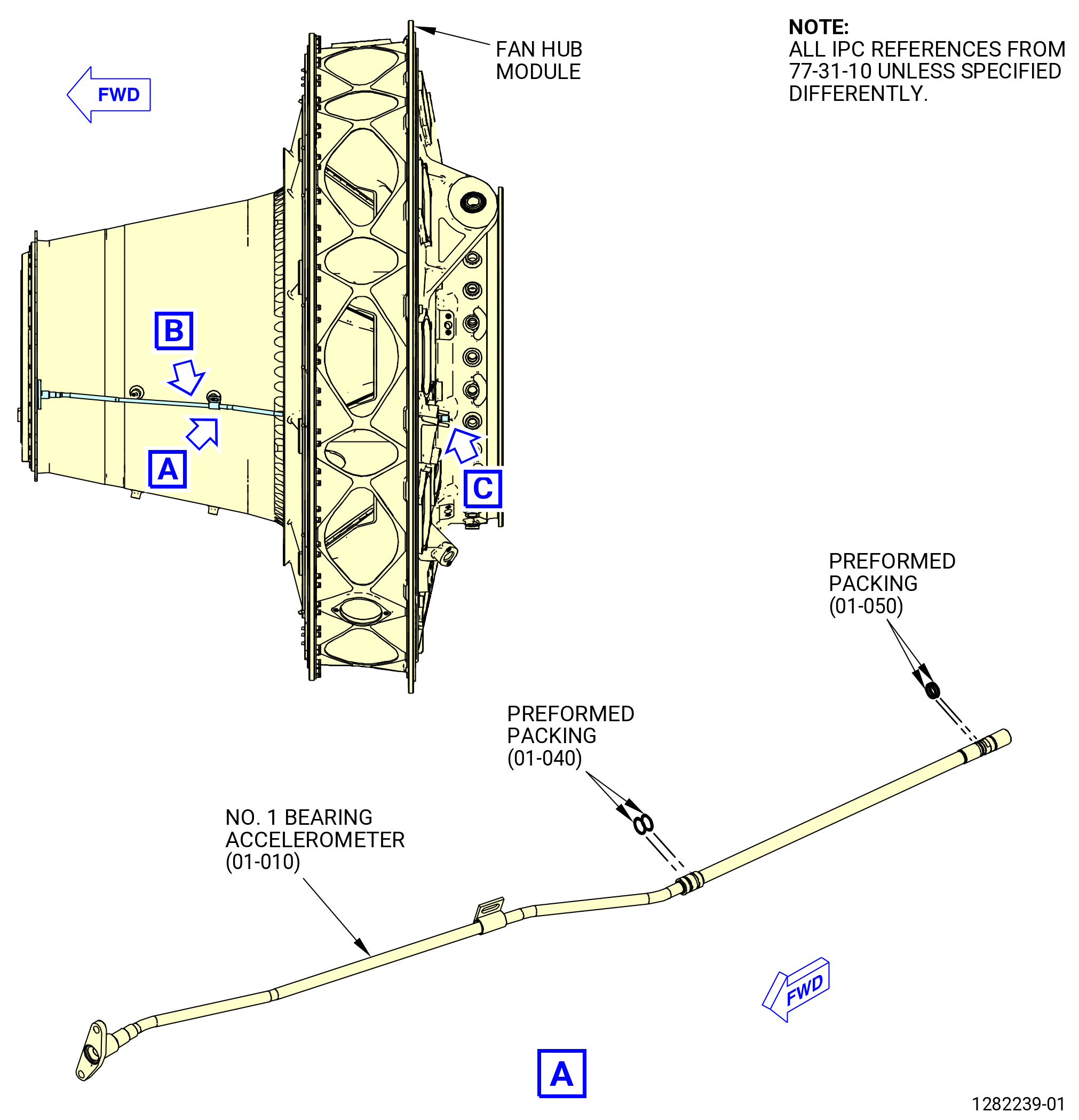
| B. | Remove the No. 1 bearing accelerometer (66A00) as follows. Refer to Figure 302. |
| (1) | Find the aft end No. 1 bearing accelerometer approximately at the 8:30 o'clock position aft looking forward (ALF) on the aft side of the fan hub module. |
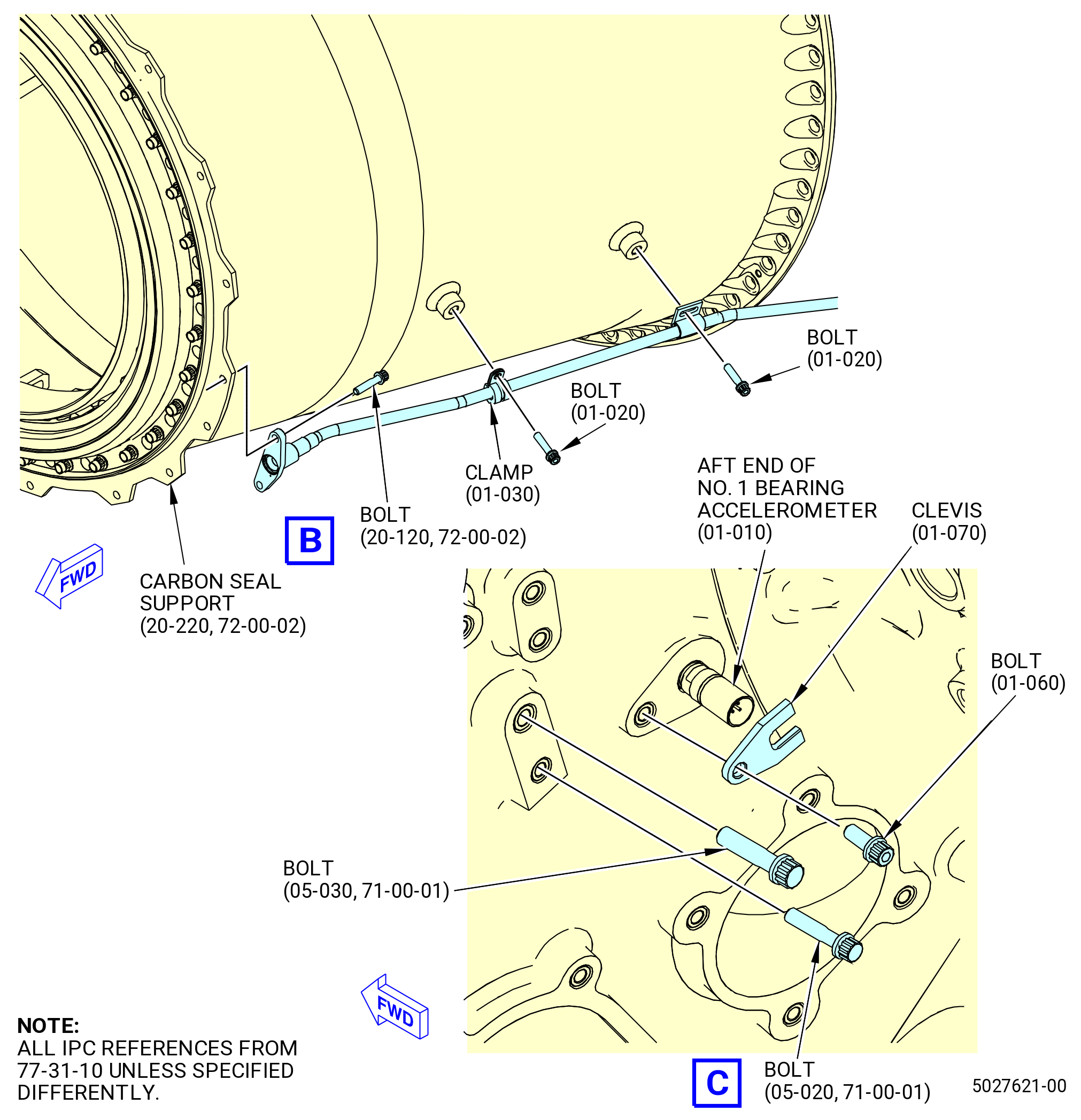
| (2) | Remove the bolt (66A21) and the clevis (66A81) that attach the No. 1 bearing accelerometer to the fan hub module. |
| Subtask 72-00-23-020-019 |
| * * * FOR 1B/P/G03.1B/P/G04.1B/P1/G01 |
| * * * PRE SB 72-0161( Removal of the Bearing Accelerometer - Non-PIP 2 Configuration ) |
| (3) | Remove the two bolts (01-020 , 77-31-10) (SIN 66A20) and the clamp (01-030 , 73-31-10) (SIN 66A80) that attach the center section of the accelerometer to the No. 1 bearing support housing (housing) (01-010 , 72-23-00) (SIN 84001). |
| * * * END PRE SB 72-0161 |
| Subtask 72-00-23-020-020 |
| * * * FOR ALL PIP 2 |
| * * * SB 72-0161( Removal of the Bearing Accelerometer - PIP 2 Configuration ) |
| (3).A. | Remove the bolts (01-021 , 77-31-10) (SIN 66A20) and (01-080 , 77-31-10) (SIN 66A27) and the clamp (01-030 , 77-31-10) (SIN 66A80) that attach the center section of the accelerometer to the housing (01-010 , 72-23-00) (SIN 84001). |
| * * * END SB 72-0161 |
| Subtask 72-00-23-020-021 |
| * * * FOR ALL |
| (4) | Remove the two bolts and nuts that attach the No. 1 bearing accelerometer to the aft side of the carbon seal support (011A3). |
| (5) | Carefully pull the No. 1 bearing accelerometer forward out of the fan hub module and away from the No. 1 bearing support housing (housing) (84001). |
| (6) | Remove and discard the two preformed packings (01-040 , 77-31-10) (SIN 66A50) and (01-050 , 77-31-10) (SIN 66A51) from the grooves on the aft end and the middle section of the No. 1 bearing accelerometer. |
| Subtask 72-00-23-020-005 |
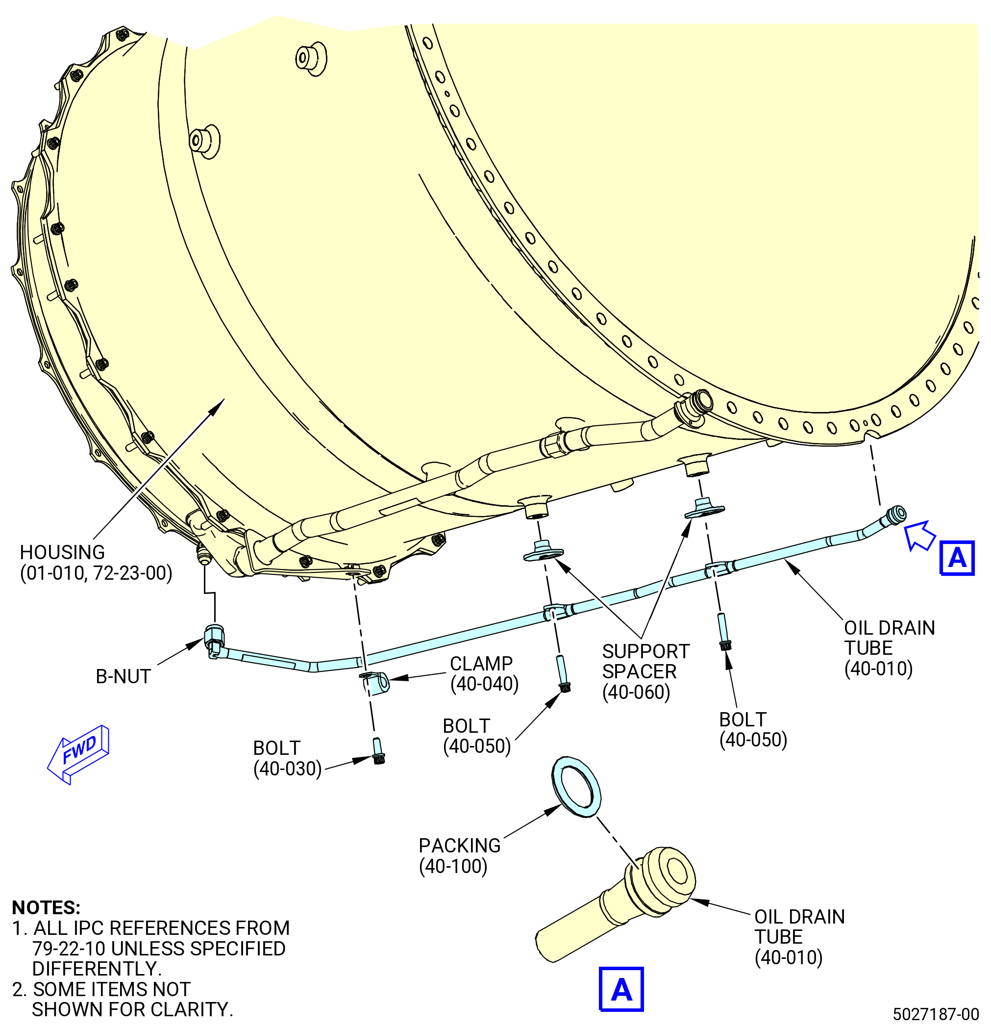
| C. | Remove the oil drain tube (484A0) from the outside of the housing (84001) as follows. Refer to Figure 303. |
| (1) | Loosen the B-nut on the oil drain tube where it is connected to the fitting at the 6:00 o'clock position on the housing. |
| (2) | Remove the bolt (484F2) and the clamp (484V0) that attach the oil drain tube to the bracket of the scavenge oil tube at the 6:00 o'clock position under the housing. |
| (3) | Remove the two bolts (484F1) and support spacers (484T1) from the center section of the oil drain tube. |
| (4) | Carefully pull the aft section of the oil drain tube forward and out of the tube hole where it is connected to the fan hub frame. |
| (5) | Remove and discard the packing (40-100 , 79-22-10) (SIN 484N2) at the aft end of the oil drain tube. |
| Subtask 72-00-23-020-006 |
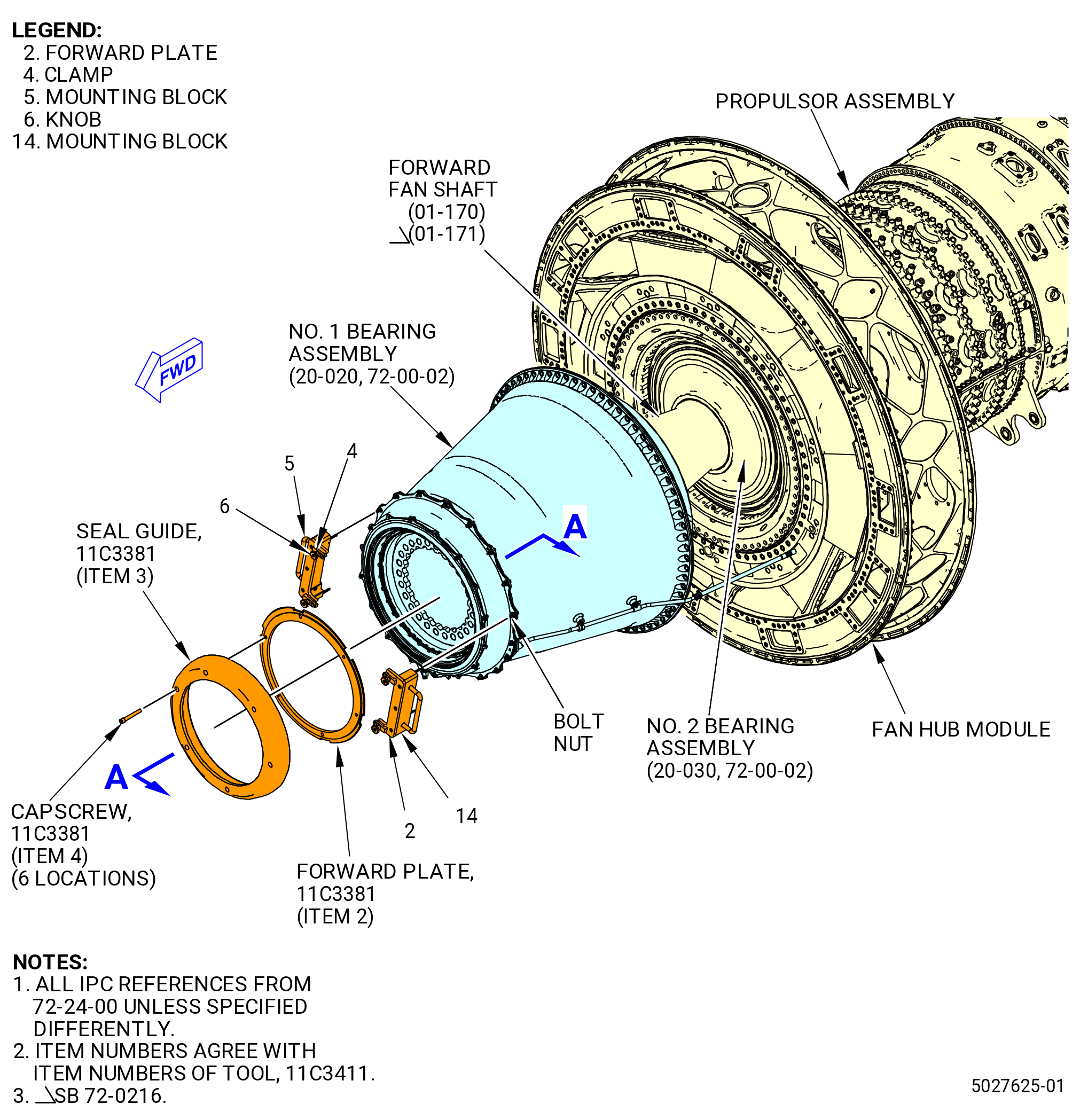
| D. | Remove the No. 1 bearing carbon seal support (seal support) (011A3) as follows. Refer to Figure 304. |
| (1) | Install the 11C3381 seal guide on the forward end of the No. 1 bearing assembly (01100) as follows: |
| (a) | Align the six cutouts in the plate (item 2) with the six tabs on the No. 1 bearing seal mating ring (mating ring) (011A5). |
| NOTE: |
|
| (b) | Push down and engage the plate (item 2) in the grove of the mating ring (011A5) and rotate approximately 30 degrees in a clockwise or counterclockwise direction to lock mating ring between the plate and the guide. |
| (c) | Attach the plate and the guide with the six screws (item 4). |
| (2) | Remove the bolts and nuts that attach the seal support to the No. 1 bearing assembly. |
| (3) | Attach the 11C3411 installation fixture to the seal support as follows: |
| (a) | Install the mounting blocks (items 5 and 14) at the 3:00 o'clock and 9:00 o'clock positions. Engage the diamond pins in the boltholes in the aft flange of the carbon seal support. |
| (b) | Rotate the mounting blocks (items 5 and 14) inward until the forward plate (item 2) is under the forward flange of the seal support. |
| (c) | Put the clamps (item 4) over the bolts that attach the carbon seal drain to the seal support. |
| (d) | Tighten the knobs (item 6) to secure the 11C3411 installation fixture to the seal support. |
| (4) | Use three jackscrews to remove the seal support from the No. 1 bearing assembly. |
| NOTE: |
|
| (5) | Put the seal support on a clean work surface. |
| (6) | Remove the 11C3411 installation fixture. |
| (7) | Remove the No. 1 bearing seal fwd gasket (seal gasket) (20-230 , 72-00-02) (SIN 011N0) from the seal support. Refer to Figure 306. |
| (8) | Loosen the screws (item 4) and remove the 11C3381 seal guide from the forward flange of the No. 1 bearing assembly. |
| (9) | Disengage and remove the plate (item 2) from the No. 1 bearing mating ring. |
| Subtask 72-00-23-020-007 |
| * * * PRE SB 79-0006( Scavenge Oil Tube with One Cushioned Loop Clamp ) |
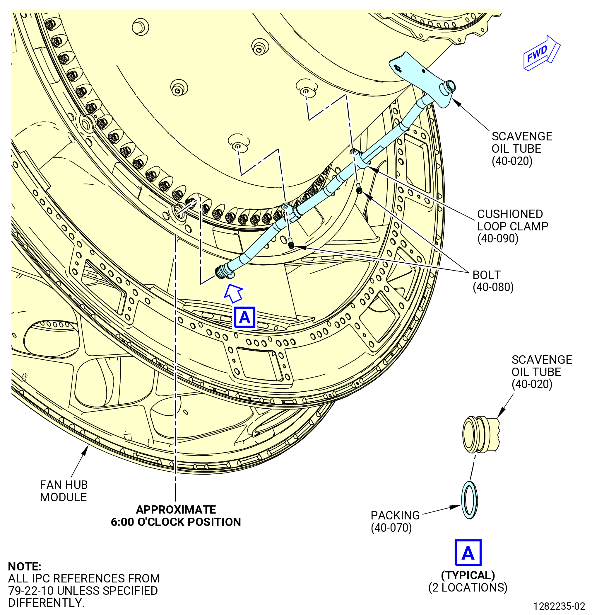
| E. | Remove the scavenge oil tube (40-020 , 79-22-10) (SIN 451A0) from the fan hub module. Refer to Figure 305 and do as follows: |
| (1) | Remove the two bolts (451F1) and cushioned loop clamp (40-090 , 79-22-10) (SIN 451V0) that attach the scavenge oil tube to the housing (84001). |
| (2) | Remove the cushioned loop clamp (40-090 , 79-22-10) (SIN 451V0) from the scavenge oil tube. |
| (3) | Pull the scavenge oil tube from the port where it is connected to the fan hub module and remove it from the housing. |
| (4) | Remove and discard the packings (40-070 , 79-22-10) (SIN 451N0) at each end of the scavenge oil tube. |
| * * * END PRE SB 79-0006( ) |
| Subtask 72-00-23-020-018 |
| * * * SB 79-0006( Scavenge Oil Tube with Two Cushioned Loop Clamps ) |
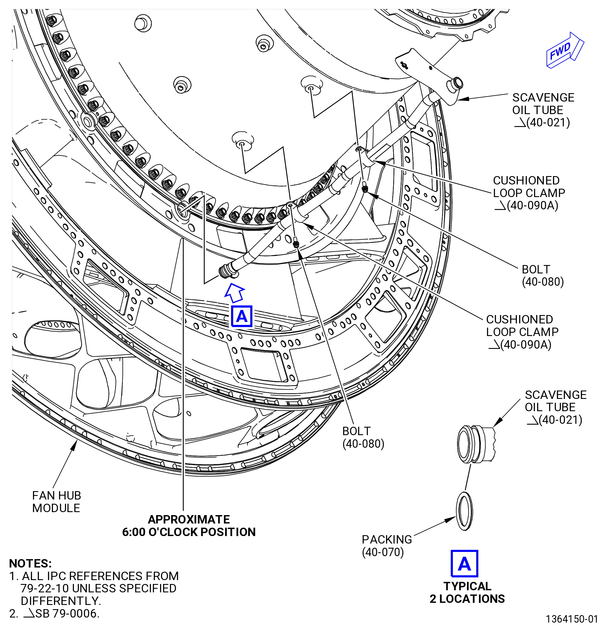
| E.A. | Remove the scavenge oil tube (40-021 , 79-22-10) (SIN 451A0) from the fan hub module. Refer to Figure 305A and do as follows: |
| (1) | Remove the two bolts (451F1) and two cushioned loop clamps (40-090A , 79-22-10) (SIN 451V0) that attach the scavenge oil tube to the housing (84001). |
| (2) | Remove the two cushioned loop clamps (40-090A , 79-22-10) (SIN 451V0) from the scavenge oil tube. |
| (3) | Pull the scavenge oil tube from the port where it is connected to the fan hub module and remove it from the housing. |
| (4) | Remove and discard the packings (40-070 , 79-22-10) (SIN 451N0) at each end of the scavenge oil tube. |
| * * * END SB 79-0006( ) |
|
|
| Subtask 72-00-23-040-001 |
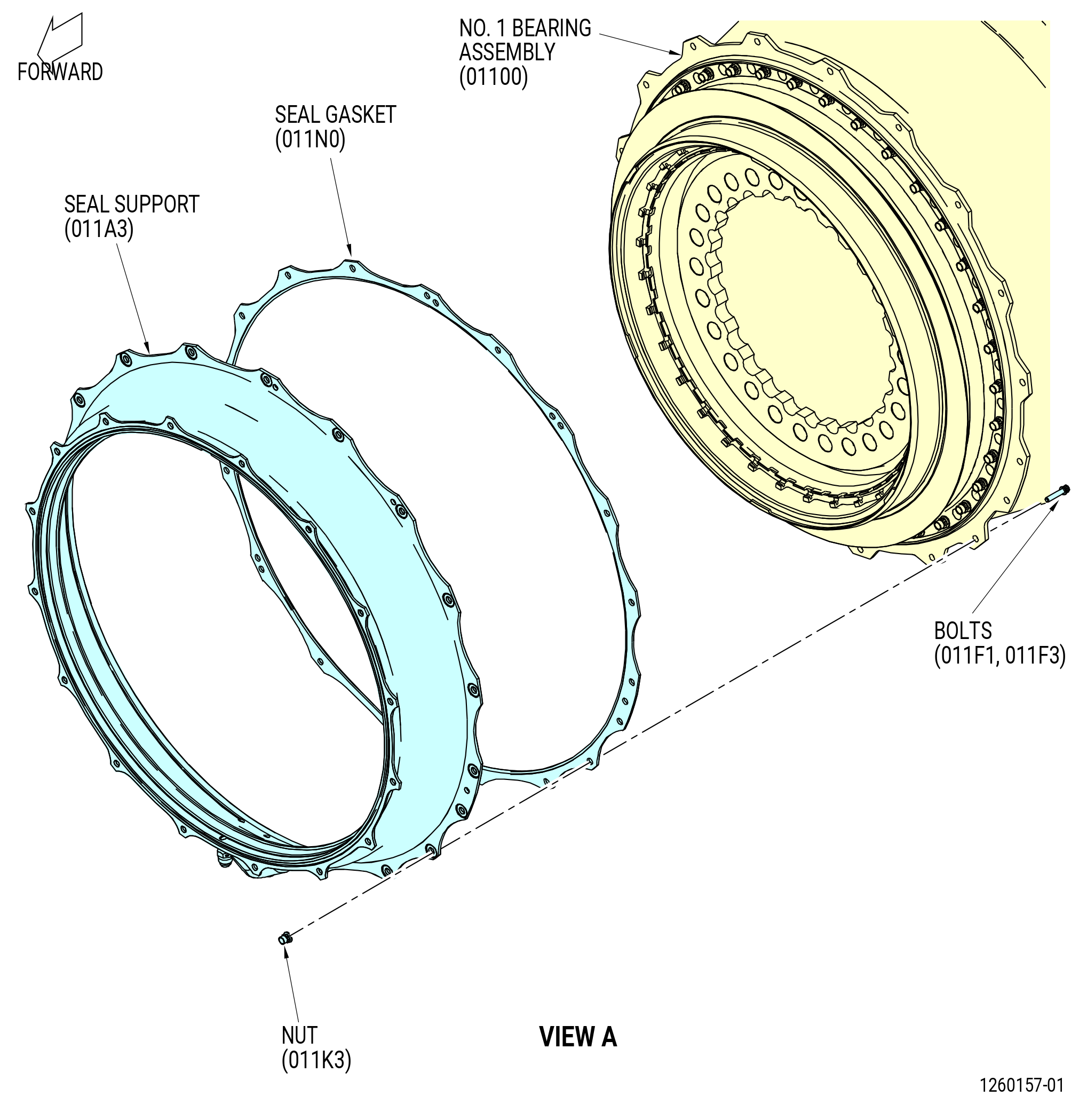
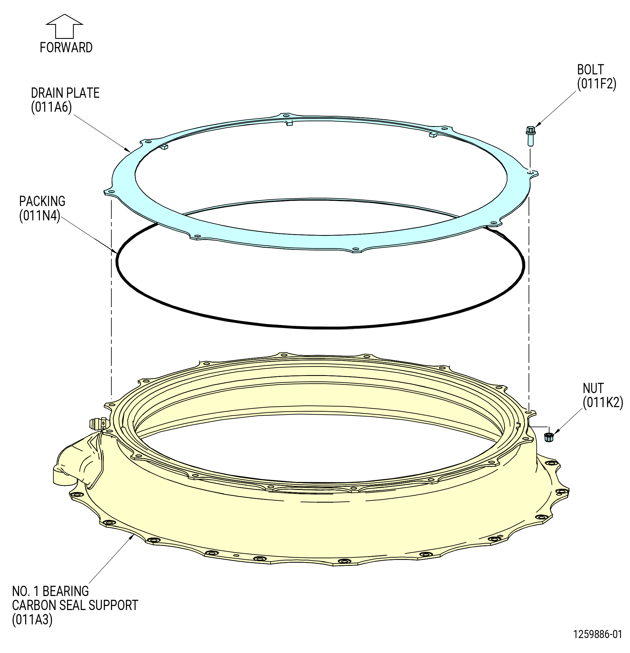
| F. | Disassemble the seal support (011A3) as follows. Refer to Figure 306. |
| (1) | Remove the eight nuts (011K3) and bolts (011F1, 011F3) that connect the No. 1 bearing seal drain (drain plate) (011A6) to the seal support. Refer to Figure 307. |
| (2) | Remove and discard the packing (20-160 , 72-00-02) (SIN 011N4). |
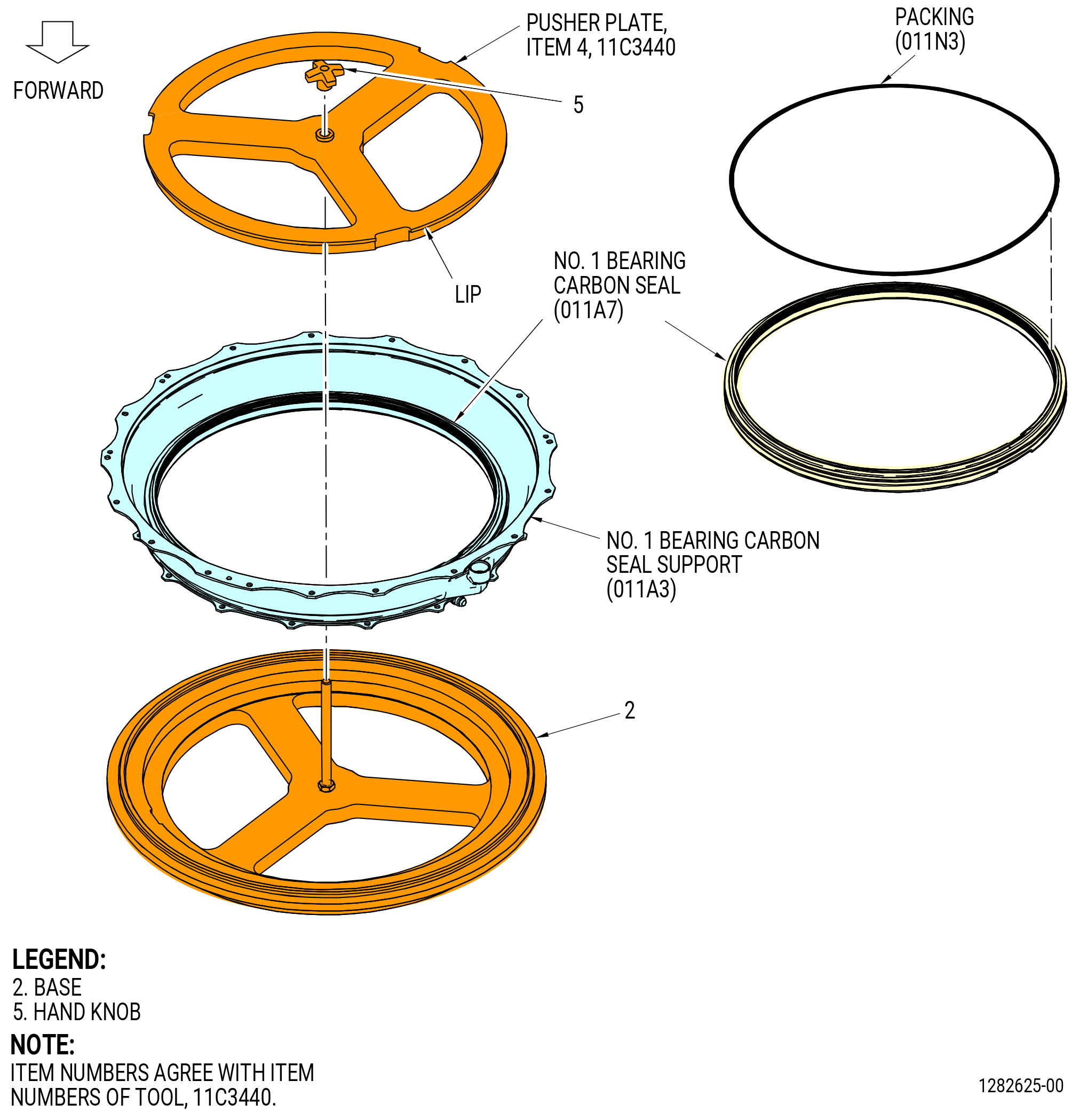
| (3) | Remove the No. 1 bearing carbon seal (carbon seal) (011A7) from the seal support as follows. Refer to Figure 308. |
| (a) | Put the seal support forward side down (small diameter side down) on the base (item 2) of the 11C3440 carbon seal fixture. |
| (b) | Attach the pusher plate (item 4) with the lip side up. |
| (c) | Thread the hand knob (item 5) onto the fixture base stud and tighten it against the pusher plate (item 4) until the carbon seal is pushed out of the seal support. |
| (d) | Loosen the hand knob (item 5) completely and remove the pusher plate (item 4) from the 11C3440 carbon seal fixture. |
| (4) | Remove and discard the packing (011N3) from the aft side of the carbon seal. |
| Subtask 72-00-23-020-008 |
| G. | Remove the No. 1 bearing nut (bearing nut) (011A1) as follows: |
| (1) | Remove the retaining ring (011W0) and the anti-rotation spring clips (spring clips) (011W1) from inside the teeth of the No. 1 bearing nut (bearing nut) (011A1). Refer to Figure 309. |
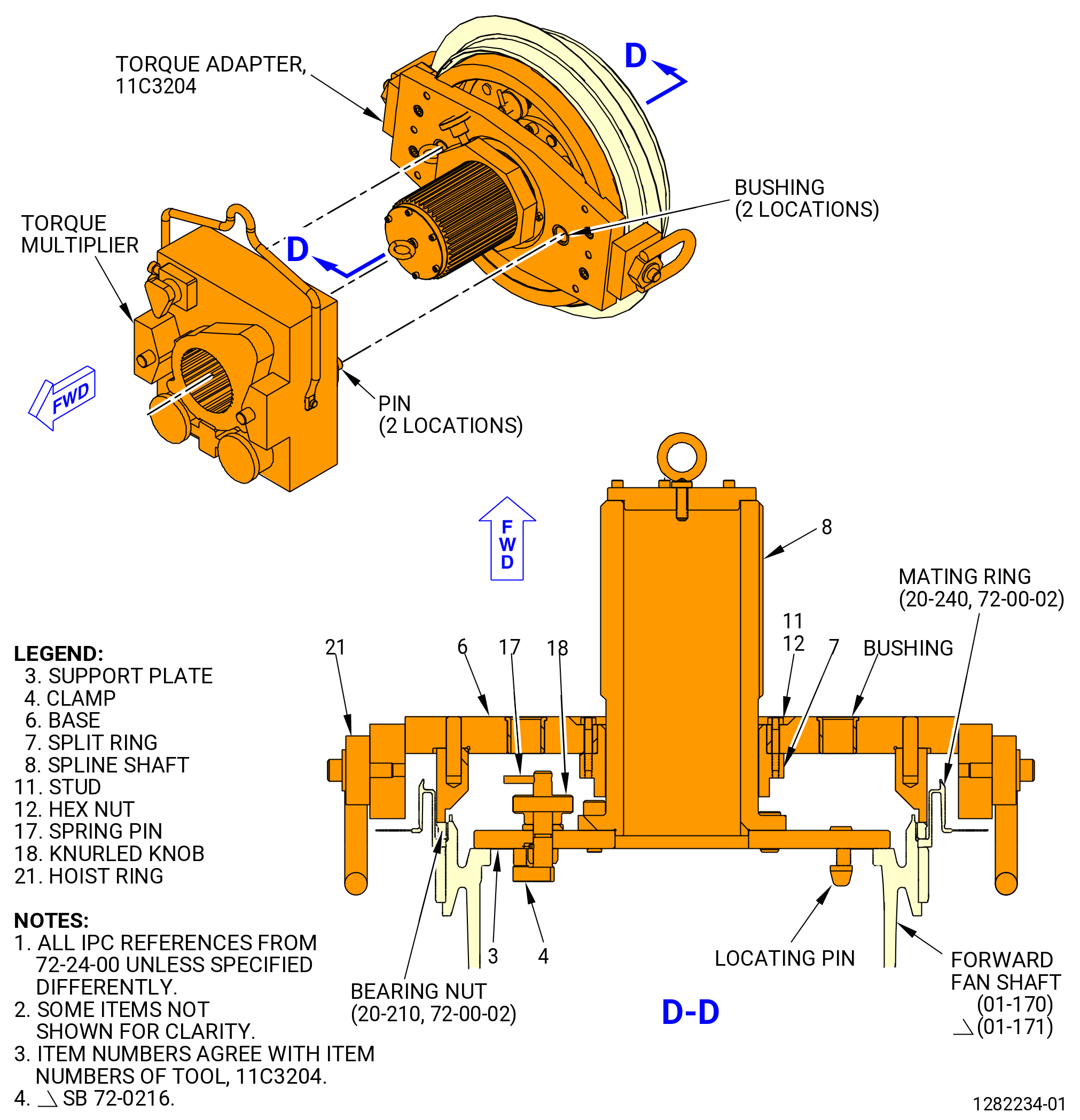
| (2) | Install the 11C3204 torque adapter on the bearing nut as follows. Refer to Figure 310. |
| (a) | Turn the clamps (item 4) to the disengaged position. |
| (b) | Engage the locating pins on the support plate (item 3) with the boltholes in the forward fan shaft (01-170 , 72-24-00) (SIN 81002) or (01-171 , 72-24-00) (SIN 81002). |
| (c) | Turn the clamps (item 4) to the engaged position. |
| (d) | Turn the knurled knob (item 18) and attach the support plate (item 3) with three clamps (item 4). |
| (e) | Assemble the base (item 6) on the studs (item 11) of the split ring (item 7). Turn the base until it engages the wrench slots of the bearing nut. Attach the base to the split ring with the two nuts (item 12). |
| (f) | Install a torque multiplier over the spline shaft (item 8) and turn until the pins of the torque multiplier engage the bushings on the base (item 6). |
| CAUTION: |
|
| (3) | Use the torque multiplier and loosen the bearing nut. Remove the torque multiplier when the bearing nut turns freely. |
| NOTE: |
|
| (4) | Remove the 11C3204 torque adapter from the bearing nut as follows: |
| (a) | Loosen the two hex nuts (item 12) that attach the split ring (item 7) to the base (item 6). Remove the base. |
| (b) | Turn the knurled knob (item 18) and disengage the three clamps (item 4) that attach the support plate (item 3) to the forward fan shaft. |
| (5) | Use your hand and remove the bearing nut from the bore of the No. 1 bearing assembly (01100). Refer to Figure 309. |
| Subtask 72-00-23-020-009 |
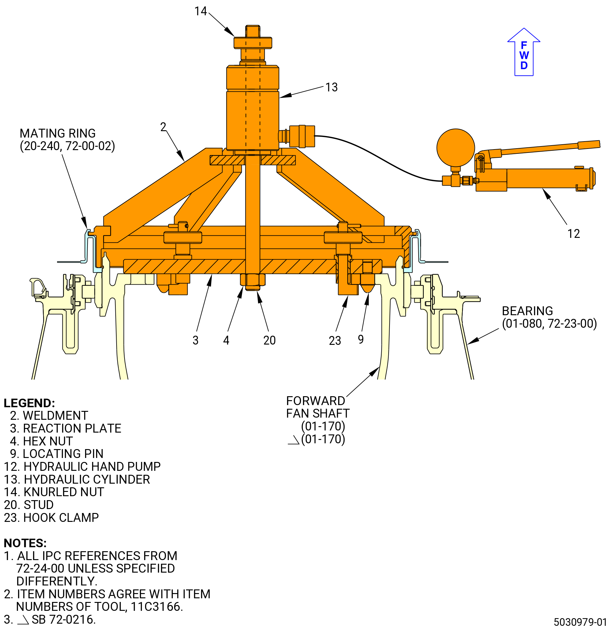
| H. | Remove the mating ring (011A5) as follows. Refer to Figure 311. |
| (1) | Install the 11C3166 install seal fixture on the forward fan shaft (01-170 , 72-24-00) (SIN 81002) or (01-171 , 72-24-00) (SIN 81002) as follows: |
| (a) | Turn the hook clamps (item 23) to the disengaged position. |
| (b) | Align the locating pins (item 9) of the reaction plate (item 3) with the boltholes in the forward fan shaft. |
| (c) | Attach the reaction plate (item 3) to the forward fan shaft. Turn the hook clamps (item 23) and tighten the knurled knobs (item 6) to attach the forward fan shaft. |
| (d) | Install the hydraulic cylinder (item 13) as follows: |
| 1 | Install the stud (item 20) with the short end down and through the reaction plate (item 3) |
| 2 | Attach the stud (item 20) to the reaction plate (item 3) with the nut (item 4). |
| (e) | Install the weldment (item 2) over the stud (item 20). |
| (f) | Align the slots in the outside lip of the weldment (item 2) with the inside diameter tabs of the seal. |
| (g) | Push the weldment (item 2) completely against the seal and turn the weldment approximately 30 degrees to engage the tabs of the weldment. |
| WARNING: |
|
| (2) | Connect the hydraulic hand pump (item 12) to the fitting on the hydraulic cylinder (item 13). Apply sufficient hydraulic pressure to push the weldment against the seal and move the seal mating ring forward out of the No. 1 bearing assembly. |
| (3) | Remove the weldment (item 2) and the seal and put on a clean work surface. |
| (4) | Remove the 11C3166 install seal fixture from the forward fan shaft as follows: |
| (a) | Release the hydraulic pressure on the hand pump (item 12). |
| (b) | Remove the hex nut (item 4) and remove the hydraulic cylinder (item 13) from the reaction plate (item 3). |
| (c) | Remove the reaction plate (item 3) by loosening the knurled knobs (item 6) and disengage the hook clamps (item 23). |
| (d) | Remove the seal from the weldment (item 2). Turn the weldment 30 degrees to disengage the tabs from the seal. |
| Subtask 72-00-23-020-010 |
| I. | Attach the support and lift tools to the No. 1 bearing assembly (01100) as follows: |
| (1) | Thread the 11C3289 No. 1 bearing guide onto the forward fan shaft (01-170 , 72-24-00) (SIN 81002) or (01-171 , 72-24-00) (SIN 81002) until it touches the bearing (01-080 , 72-23-00) (SIN 011A0). Refer to Figure 312. |
| Subtask 72-00-23-020-013 |
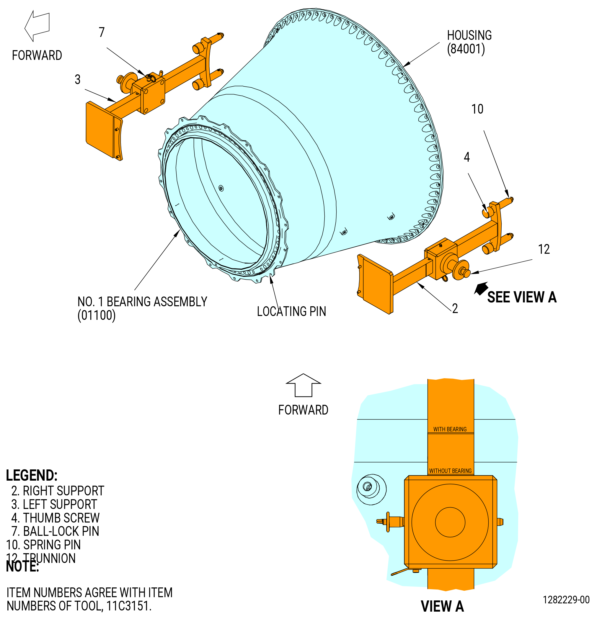
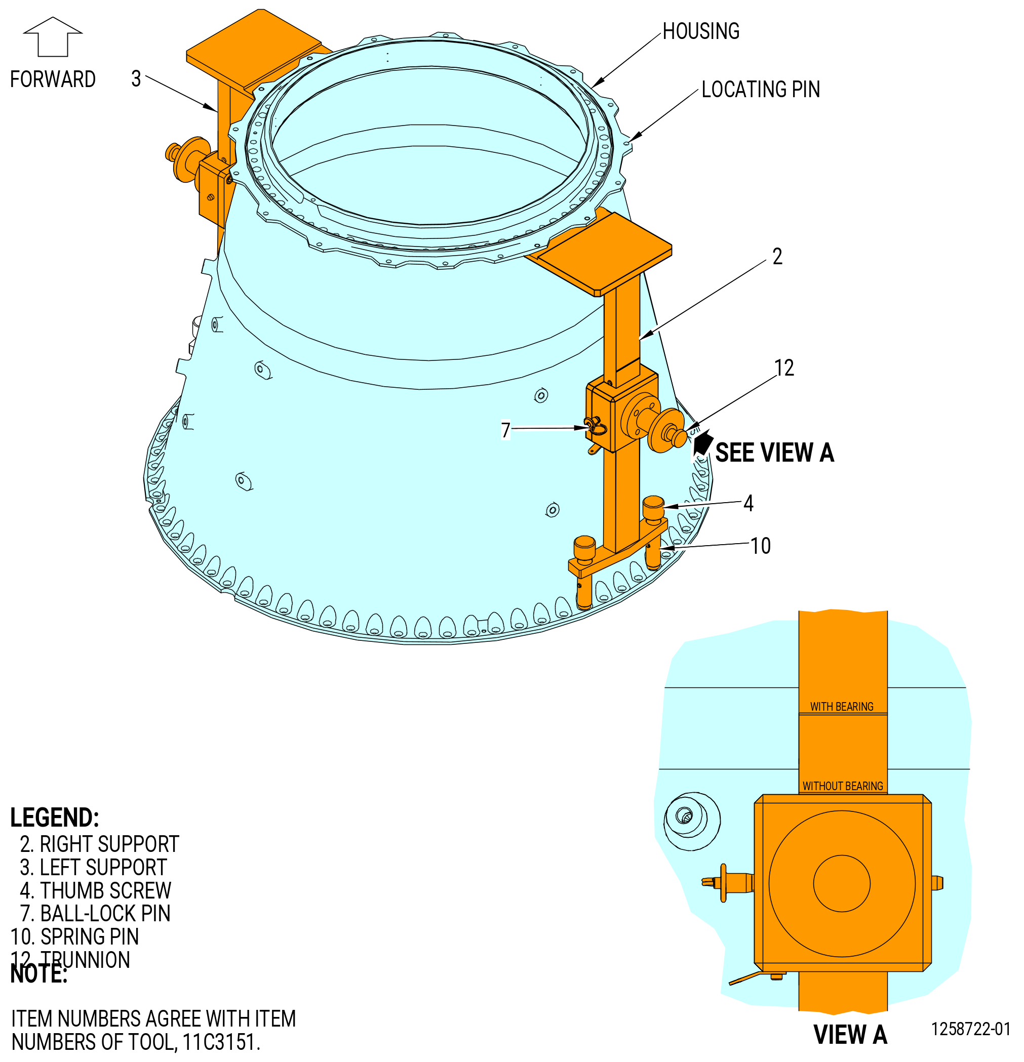
| (2) | Install the 11C3151 lift and turn fixture to the housing (84001) as follows. Refer to Figure 313. |
| (a) | Remove the bolts at the 3:00 o'clock and 9:00 o'clock positions on the aft flange of the No. 1 bearing housing. Remove the three bolts above and below the 3:00 o'clock and 9:00 o'clock positions on the aft flange. |
| (b) | Install the thumb screws (item 4) of the right support (item 2) into the boltholes in the aft flange of the housing at the 3:00 o'clock position forward looking aft (FLA). |
| (c) | Adjust the thumb screws (item 4) until the forward flange of the right support (item 2) touches the aft face of the forward flange of the housing. |
| (d) | Make sure that the locating pins of the right support (item 2) engage in the boltholes on the aft face of the housing forward flange. |
| Subtask 72-00-23-020-014 |
| (e) | Do Subtask 72-00-23-020-013 (paragraph 3.I.(2)(a) thru 3.I.(2)(d)) again for the left support (item 3). |
| (f) | Adjust the trunnions (item 12) to engage the ball lock pins (item 7). |
| Subtask 72-00-23-020-015 |
| WARNING: |
|
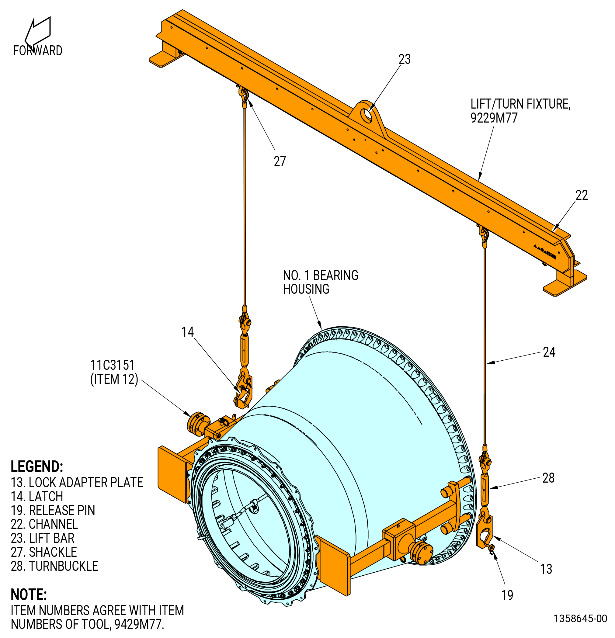
| (3) | Install the 9429M77 lift/turn fixture as follows. Refer to Figure 314. |
| (a) | Attach the hoist assemblies (item 24) to the lift bar (item 23) with the shackles (item 27). Make sure each hoist assembly is the same number of holes from the centerline of the lift bar (item 23) to keep the 9429M77 lift/turn fixture balanced. Make sure that the hoist assembly (item 24) are perpendicular (at right angle) after connecting the to the 11C3151 lift and turn fixture. |
| (b) | Attach the lock plate adapters (item 13) to the hoist assemblies (item 24) with the turnbuckle (item 28). |
| (c) | Open the latch (item 14) to attach the lock plate adapter (item 13) on the trunnions (item 5) of the 11C3151 lift and turn fixture. |
| (d) | Make sure the latch (item 14) is installed on the trunnions (item 5) of the 11C3151 lift and turn fixture and install the release pin (item 19) through the trunnion and the lock adapter plate (item 13). |
| (4) | Adjust the trunnions (item 12) of the 11C3151 lift and turn fixture to the scribe line marked WITH BEARING on each right support (item 2) and left support (item 3). Refer to Figure 317. |
| Subtask 72-00-23-020-011 |
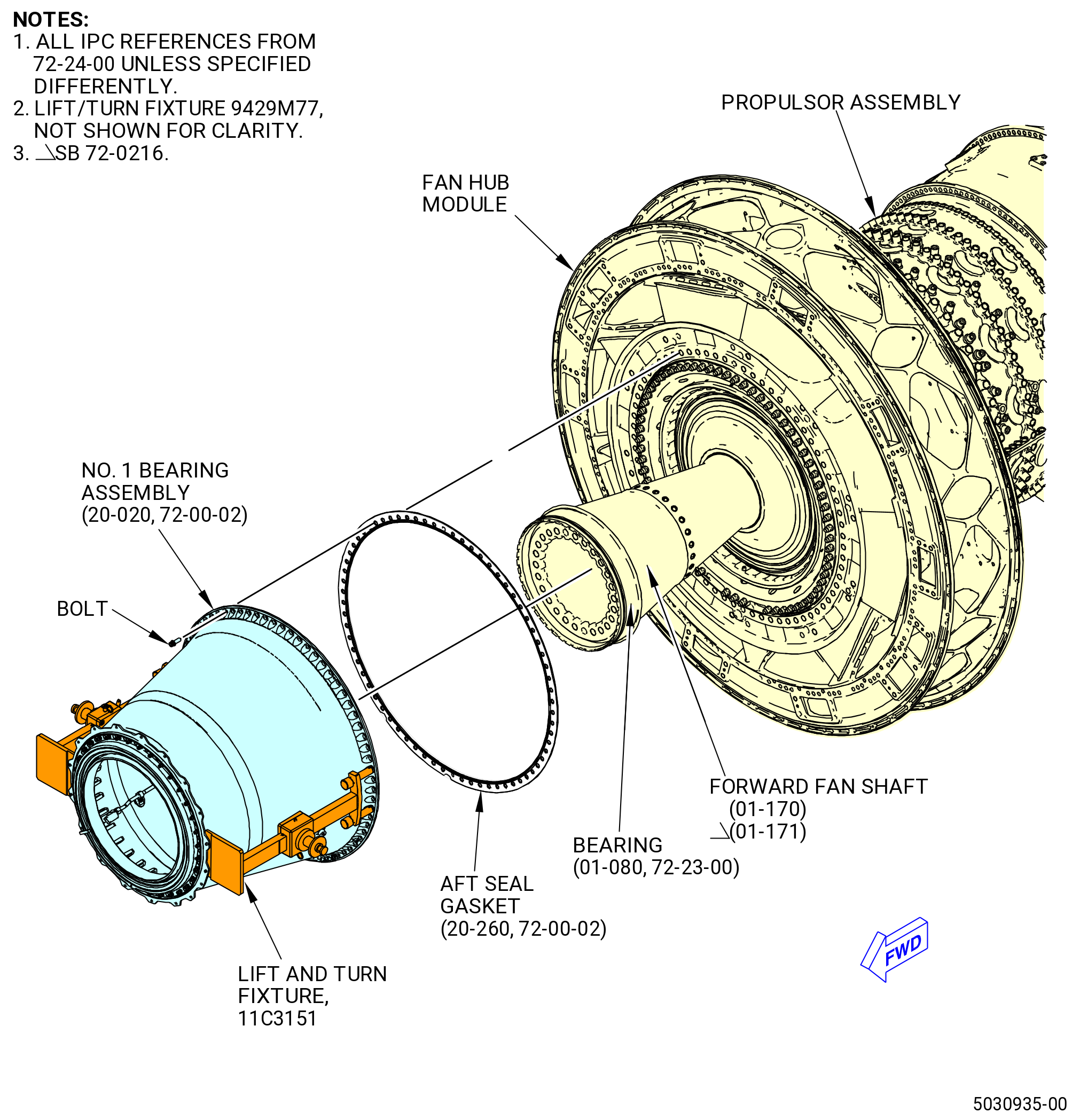
| J. | Remove the No. 1 bearing assembly (20-020 , 72-00-02) (SIN 01100) from the fan hub module. Refer to Figure 315 and do as follows: |
| NOTE: |
|
| (1) | Remove the remaining bolts around the perimeter of the No. 1 bearing assembly that connect it to the fan hub module. |
| (2) | Use 0.250-28UNJF jackscrews to disengage the No. 1 bearing assembly from the fan hub module. |
| WARNING: |
|
| CAUTION: |
|
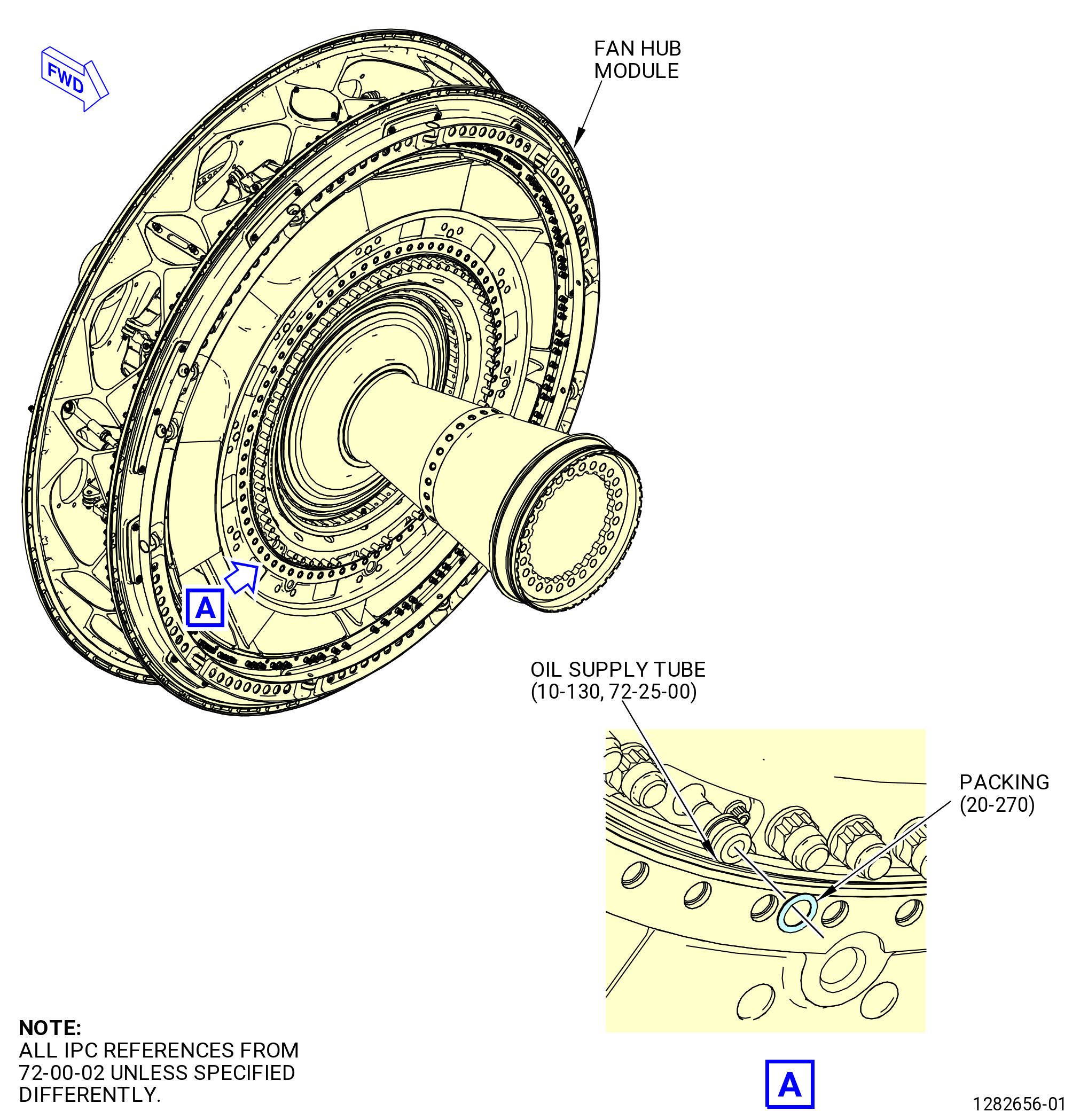
| (3) | Use the hoist to carefully pull the No. 1 bearing assembly directly forward and away from the fan hub module. Be careful not to damage the oil supply tube (442A4) or the No. 2 bearing assembly (01200). Refer to Figure 301 and Figure 315. |
| NOTE: |
|
| (4) | If necessary, rotate the No. 1 bearing assembly between horizontal and vertical positions. Refer to Figure 314. |
| (a) | Pull the release pins (item 19) of the 9429M77 lift/turn fixture from the lock adapter plate (item 13). |
| (b) | Turn the No. 1 bearing assembly on the trunnions (item 12) of the 11C3151 lift and turn fixture to the vertical position (forward end up). |
| (c) | Re-insert the release pins (item 19) of the 9429M77 lift/turn fixture into the lock adapter plate (item 13) and into the trunnions (item 12) of the 11C3151 lift/turn fixture to lock the No. 1 bearing housing into position. |
| (5) | Operate the hoist and put the No. 1 bearing assembly on a storage stand or on a clean work surface. |
| (6) | Remove the aft seal gasket (84050). Refer to Figure 315. |
| (7) | Find the oil supply tube at approximately the 7:00 o'clock position forward looking aft (FLA) on the fan hub module. Remove and discard the packing (20-270 , 72-00-02) (SIN 442N0) from the oil supply tube. Refer to Figure 316. |
| Subtask 72-00-23-020-017 |
| K. | Install the No. 1 bearing assembly (01100) on the 11C3205 assembly/disassembly stand with the forward end down as follows: |
| (1) | Attach the 9429M77 lift/turn fixture to the 11C3151 lift and turn fixture as follows. Refer to Figure 317. |
| (a) | Attach the hoist assemblies (item 24) to the lift bar (item 23) with the shackles (item 27). Make sure each hoist assembly is the same number of holes from the centerline of the lift bar (item 23) to keep the 9429M77 lift/turn fixture balanced. Make sure that the hoist assembly (item 24) are perpendicular (at right angle) after connecting the to the 11C3151 lift and turn fixture. |
| (b) | Attach the lock plate adapters (item 13) to the hoist assemblies (item 24) with the turnbuckle (item 28). |
| (c) | Open the latch (item 14) to attach the lock plate adapter (item 13) on the trunnions (item 5) of the 11C3151 lift and turn fixture. |
| (d) | Make sure the latch (item 14) is installed on the trunnions (item 5) of the 11C3151 lift and turn fixture and install the release pin (item 19) through the trunnion and the lock adapter plate (item 13). |
| (2) | Adjust the trunnions (item 12) of the 11C3151 lift and turn fixture to the scribe line marked WITH BEARING on each right support (item 2) and left support (item 3). Refer to Figure 317. |
| (3) | Install the No. 1 bearing assembly on the 11C3205 assembly/disassembly stand as follows: |
| WARNING: |
|
| (a) | Use a hoist and the 9429M77 lift/turn fixture to lift the No. 1 bearing assembly. Refer to Figure 318. |
| (b) | Remove the release pins (item 19) of the 9429M77 lift/turn fixture. Refer to Figure 314. |
| (c) | Turn the No. 1 bearing assembly to the forward end down position and install the release pins (item 19). |
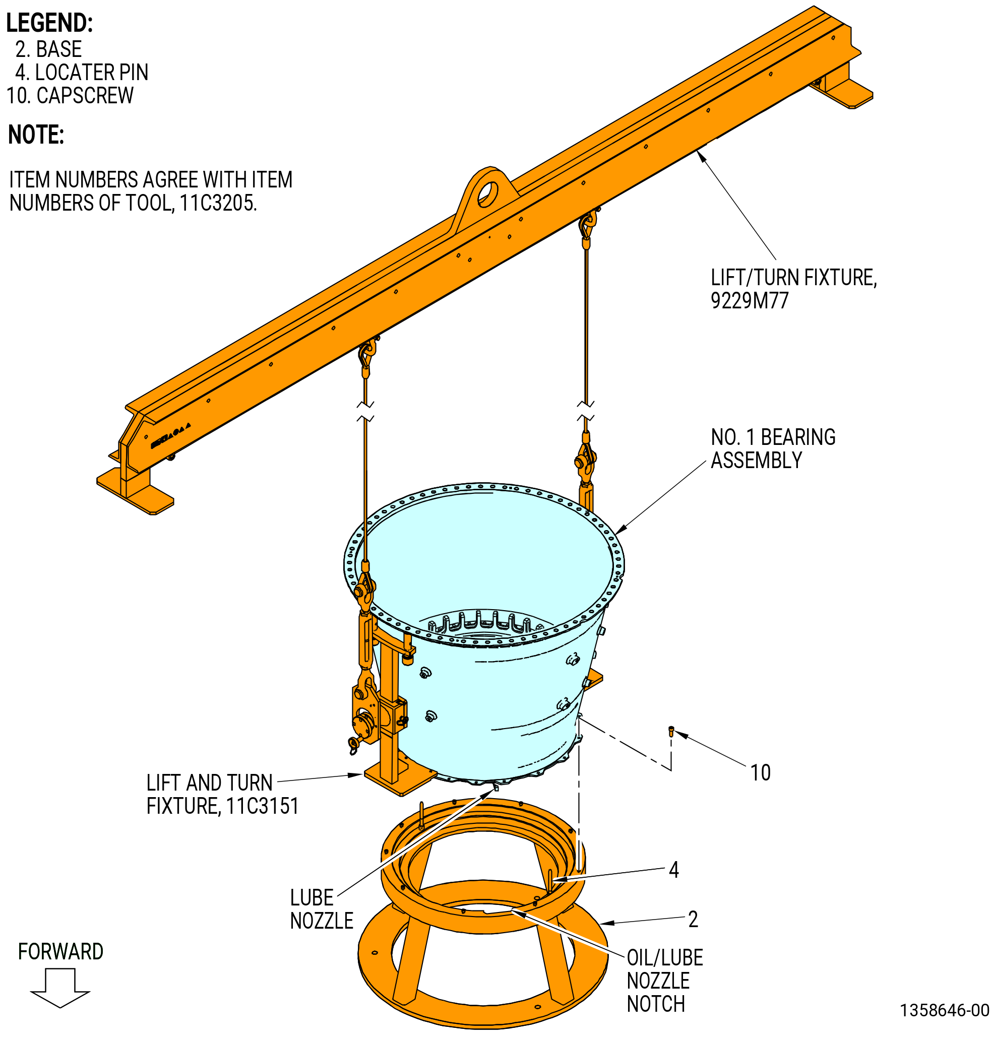
| (d) | Move the No. 1 bearing assembly over the base (item 2) of the 11C3205 assembly/disassembly stand and align the lube nozzle with the lube/oil nozzle notch in the base. Refer to Figure 318. |
| (e) | Align two boltholes in the forward flange of the No. 1 bearing assembly with the two locator pins (item 4) and lower the No. 1 bearing assembly to the base (item 2). |
| (f) | Attach the No. 1 bearing assembly to the base (item 2) with nine capscrews (item 10). |
| (g) | Remove the 9429M77 lift/turn fixture from the 11C3151 lift and turn fixture. |
| Subtask 72-00-23-020-016 |
| L. | Continue to disassemble the No. 1 bearing assembly (20-020 , 72-00-02) (SIN 01100). Refer to TASK 72-23-00-040-801 (72-23-00, Disassembly). |
| Subtask 72-00-23-510-001 |
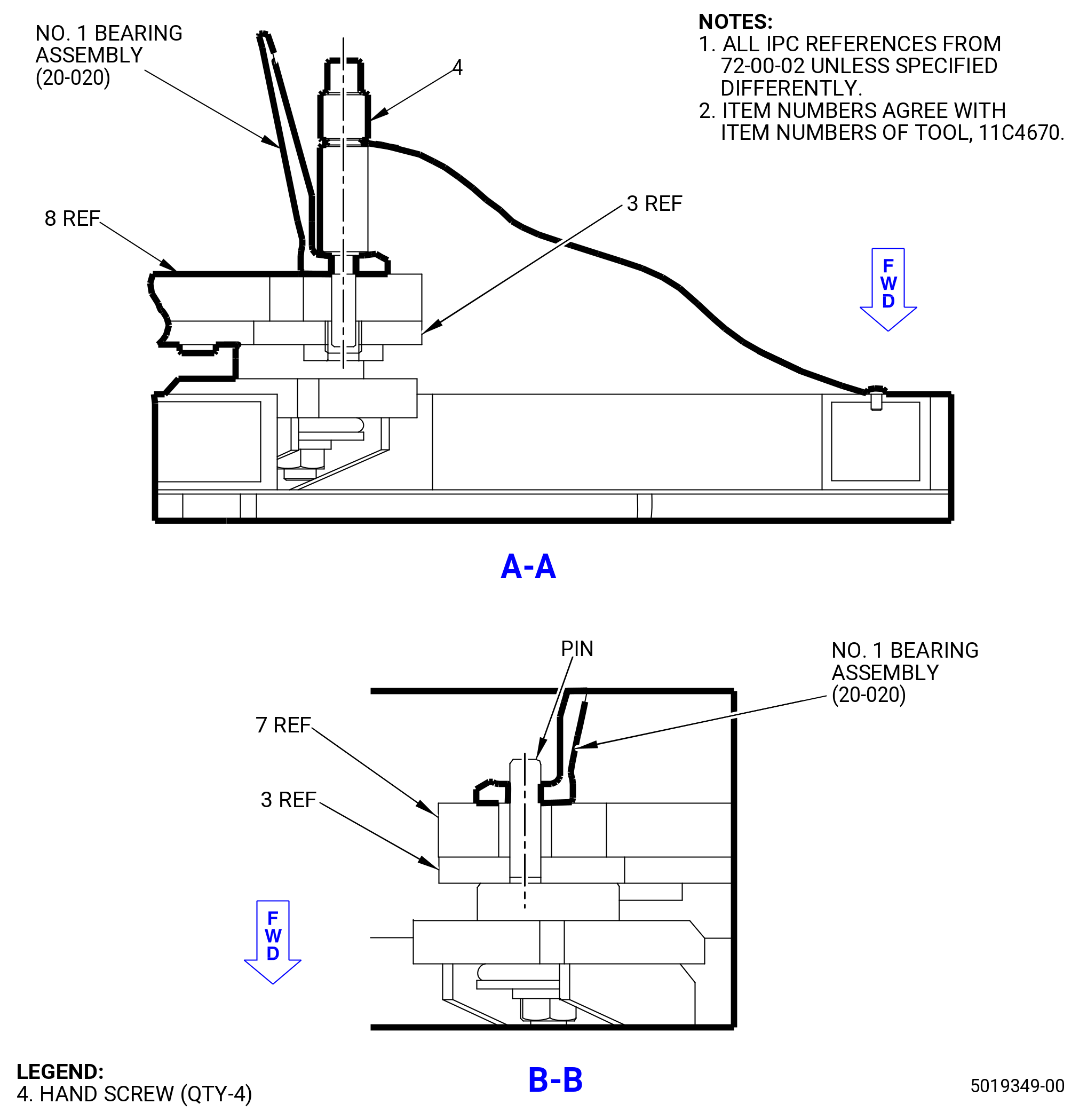
| M. | Optional procedure. Prepare the No. 1 bearing assembly (20-020 , 72-00-02) (SIN 01100) for shipment. Refer to Figure 319 and do as follows: |
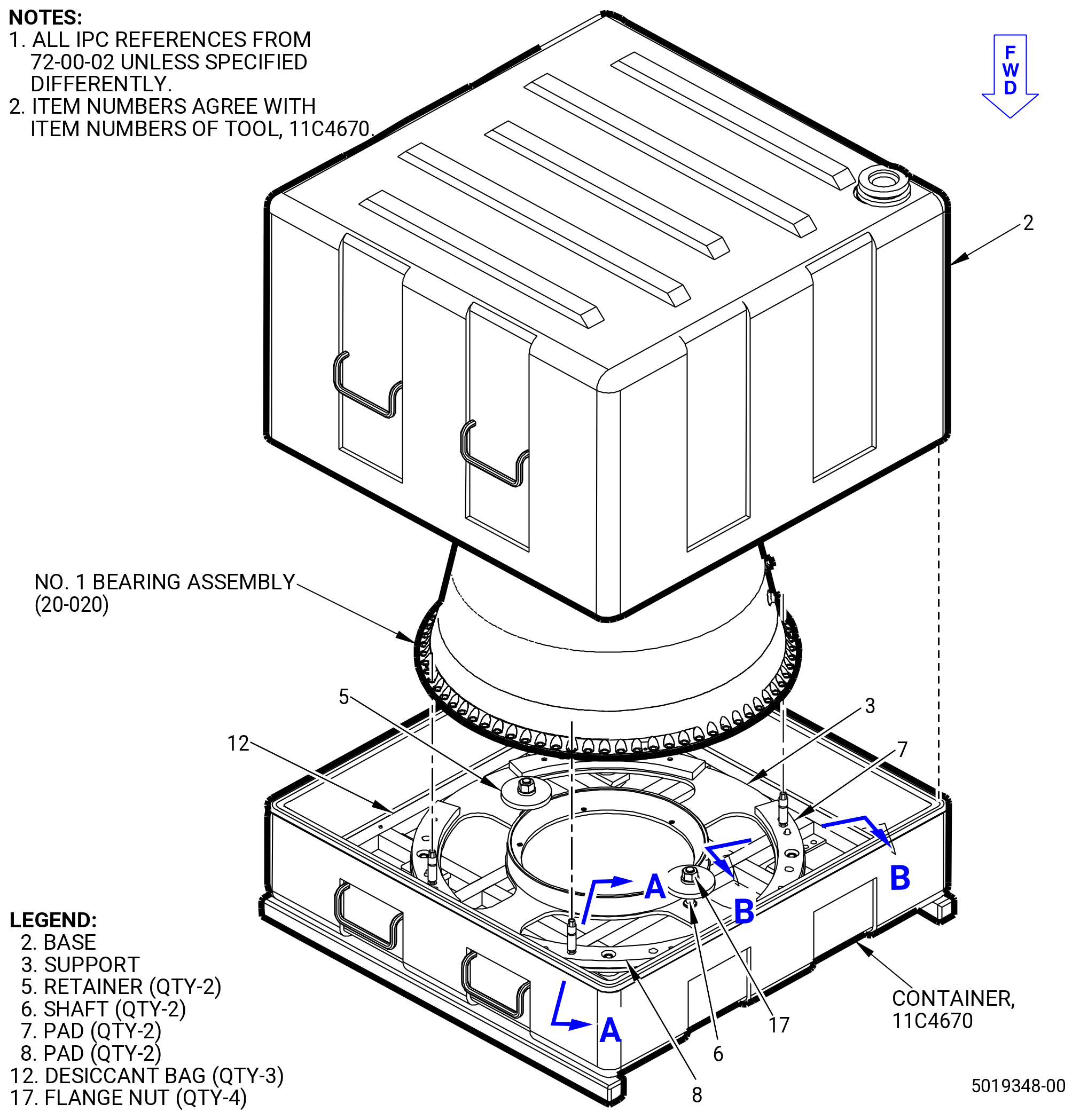
| (1) | Prepare the 11C4670 container as follows: |
| (a) | Remove the base (item 2). |
| (b) | Remove the hand screws (items 4) and the retainer (item 5) from the support (item 3). |
| (c) | Install the No. 1 bearing inner track on the circular pads (item 7) and (item 8). |
| NOTE: |
|
| (d) | Put the shaft (item 6) to install the two retainers (item 5) in their holes. |
| (e) | Put the flange nut (item 17) to attach the No. 1 bearing inner track against the support (item 3). |
| (f) | Do a visual inspection to make sure that the mating surfaces are free of any dirt, burrs, or scratches that could damage the engine hardware. |
| WARNING: |
|
| (2) | Use the 11C3151 lift and turn fixture to lift the No. 1 bearing assembly. |
| (3) | As necessary, rotate the No. 1 bearing assembly to align the top vertical position with the 11C4670 container. |
| NOTE: |
|
| CAUTION: |
|
| (4) | Align the top vertical mark of the No. 1 bearing assembly against the top vertical mark on the support (item 3). |
| (5) | Install the No. 1 bearing assembly on the pads (item 7) and (item 8). Make sure that the top vertical mark and pins align with the No. bearing module. |
| (6) | Put the four hand screws (item 4) to attach the No. 1 bearing assembly against the support (item 3). Hand tighten the hand screws (item 4). |
| (7) | Prepare for shipment as follows: |
| (a) | Put the three desiccant bags (item 12) inside the base (item 2). |
| (b) | Install the base (item 2) to close the 11C4670 container and attach it with the anti-shear locks. |