| GENX-1B CLEANING,INSPECTION,AND REPAIR MANUAL | Dated: 10/31/2017 | |
| CIR 72-00-57 , INSPECTION 001 | ||
| TURBINE REAR FRAME ASSEMBLY - INSPECTION | ||
| GENX-1B CLEANING,INSPECTION,AND REPAIR MANUAL | Dated: 10/31/2017 | |
| CIR 72-00-57 , INSPECTION 001 | ||
| TURBINE REAR FRAME ASSEMBLY - INSPECTION | ||
| * * * FOR ALL |
| TASK 72-00-57-200-801 |
| 1 . | General. |
| A. | This procedure gives instructions to do an inspection of the turbine rear frame assembly (TRF). Refer to Figure 802. |
| • |
|
| • |
|
| • |
|
| B. | Any sub-assembly or part removed for access or limited workscope must be inspected in accordance with criteria in this section. If there is no criteria, the sub-assembly or part must receive a general visual inspection (GVI) for continued serviceability. Refer to TASK 72-00-00-200-805 (72-00-00, INSPECTION 001) . If required, the component can be hand-cleaned to do a visual inspection. Refer to TASK 70-21-01-110-001 (CLEANING METHOD 1 - SOLVENT DEGREASING) or TASK 70-21-03-160-001 (CLEANING METHOD 3 - STEAM CLEANING) . GVI can not be done to components identified in TASK 05-21-00-200-801 (05-21-00, LIFE LIMITS 001) that become piece part. These components must have their appropriate mandatory inspections done, unless stated differently in an applicable Service Bulletin. |
| C. | If you find an assembly or part to be unserviceable with this procedure, refer to the applicable section of the engine manual for more disassembly and inspection procedures for the assembly or part. |
| D. | If you will fully disassemble the TRF, this inspection is not necessary. Refer to the applicable section of the engine manual for the inspection procedure for each assembly or part. |
| E. | The maintenance instructions in this Manual do not purport to cover all details or variations in equipment, nor do they provide for every possible contingency to be met in connection with installation, operation, maintenance, or GEAE certified repair facilities. The maintenance instructions are intended to be all-inclusive for a complete teardown and overhaul of the component or sub assembly. The individual procedures as written are one sequence based on General Electric experience. Alternate sequences to these maintenance instructions are at the discretion of the operator and/or overhaul shop provided the intent of the maintenance instructions is met. The operator and/or overhaul shop can select specific tasks to partially disassemble and assemble hardware or subassemblies based upon the on demand maintenance requirement of the individual engine work scope provided the final assembly configuration and requirements contained in the manual have been met. |
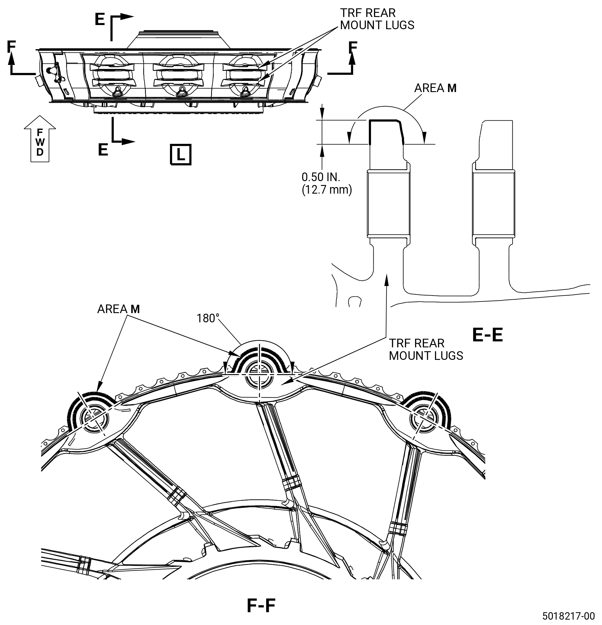
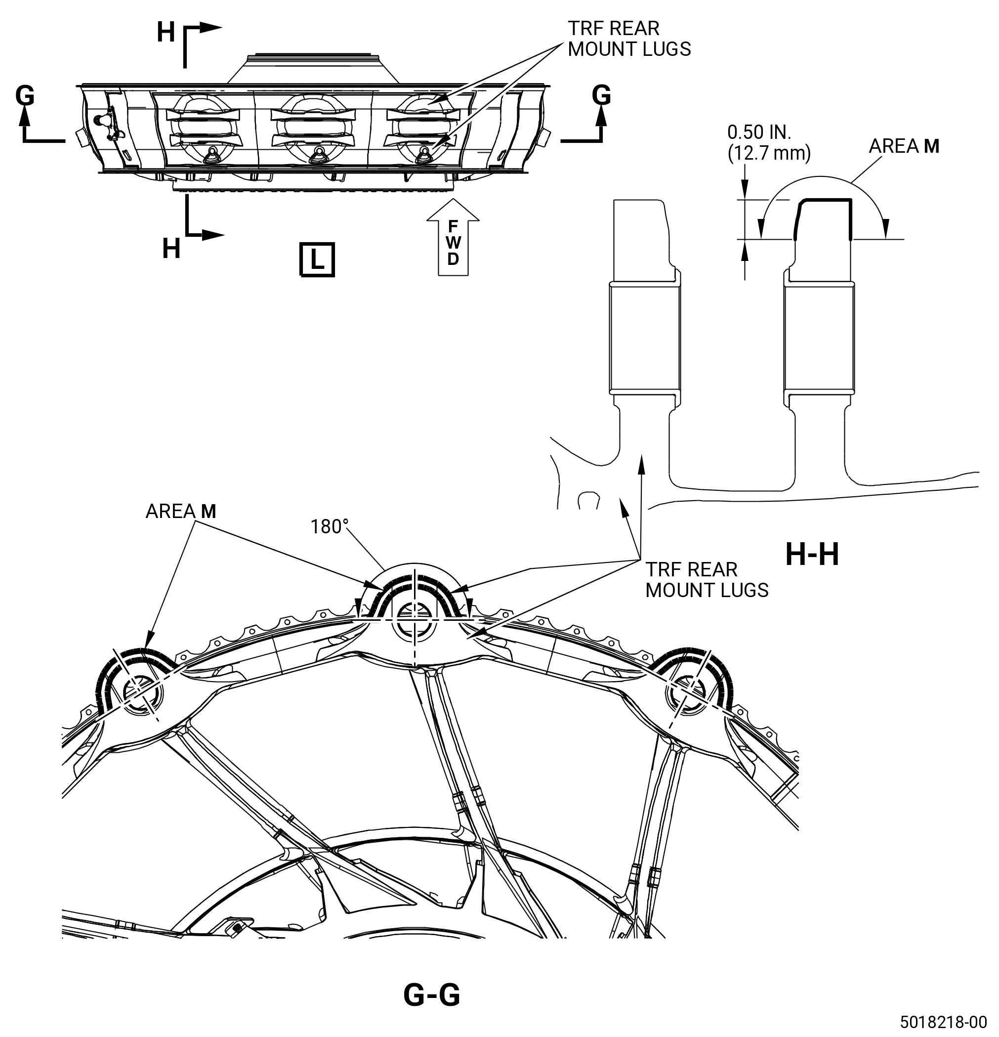
| F. | You can observe the serviceable mount surface irregularities (machined marks around the mount bushings) on the TRF mount lugs: forward side of the forward mount lugs and aft side of the aft mount lugs. The regular production process requires specific clearance between the mounting pin and TRF mount lugs. Make sure that these TRF mount lugs are machined (if necessary) around the mount lug hole. The machining effect can be noticed as a circumferential mark, a single mark or a series of small marks located circumstantially. Usually it is only one mark located on the upper half of the mount lug surface. The machining marks are smooth, shiny and can generate a surface step within specific diameters (FM and RM) from the center of the lug bushing. Refer to Figure 801. |
| NOTE: |
|
| 2 . | Tools, Equipment, and Materials. |
| NOTE: |
|
| A. | Tools and Equipment. |
| (1) | Special Tools. None. |
| (2) | Standard Tools and Equipment. None. |
| (3) | Locally Manufactured Tools. None. |
| B. | Consumable Materials. None. |
| C. | Referenced Procedures. |
| D. | Expendable Parts. None. |
| 3 . | Specific Inspection Procedure. |
| Subtask 72-00-57-230-001 |
| CAUTION: |
|
| * * * PRE SB 72-0063 |
| * * * PRE SB 72-0138 |
| * * * PRE SB 72-0160 |
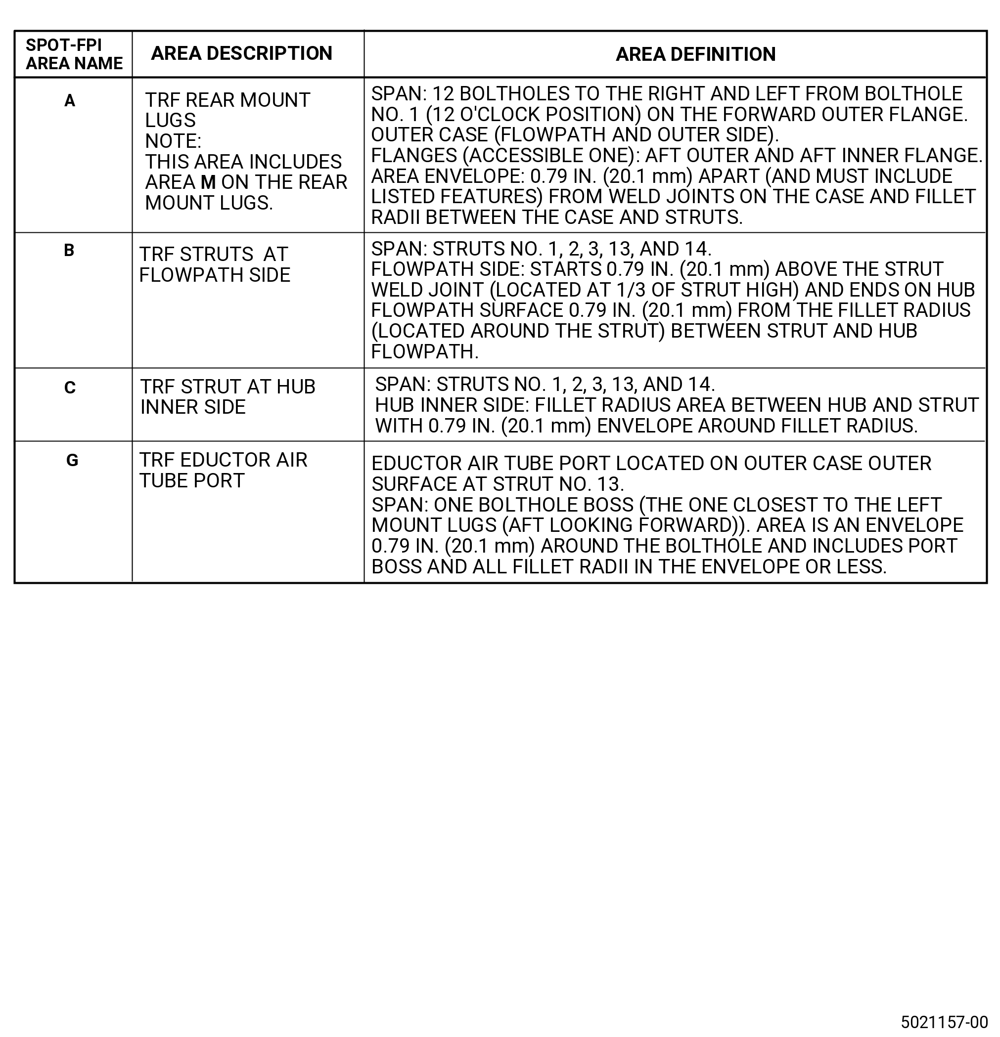
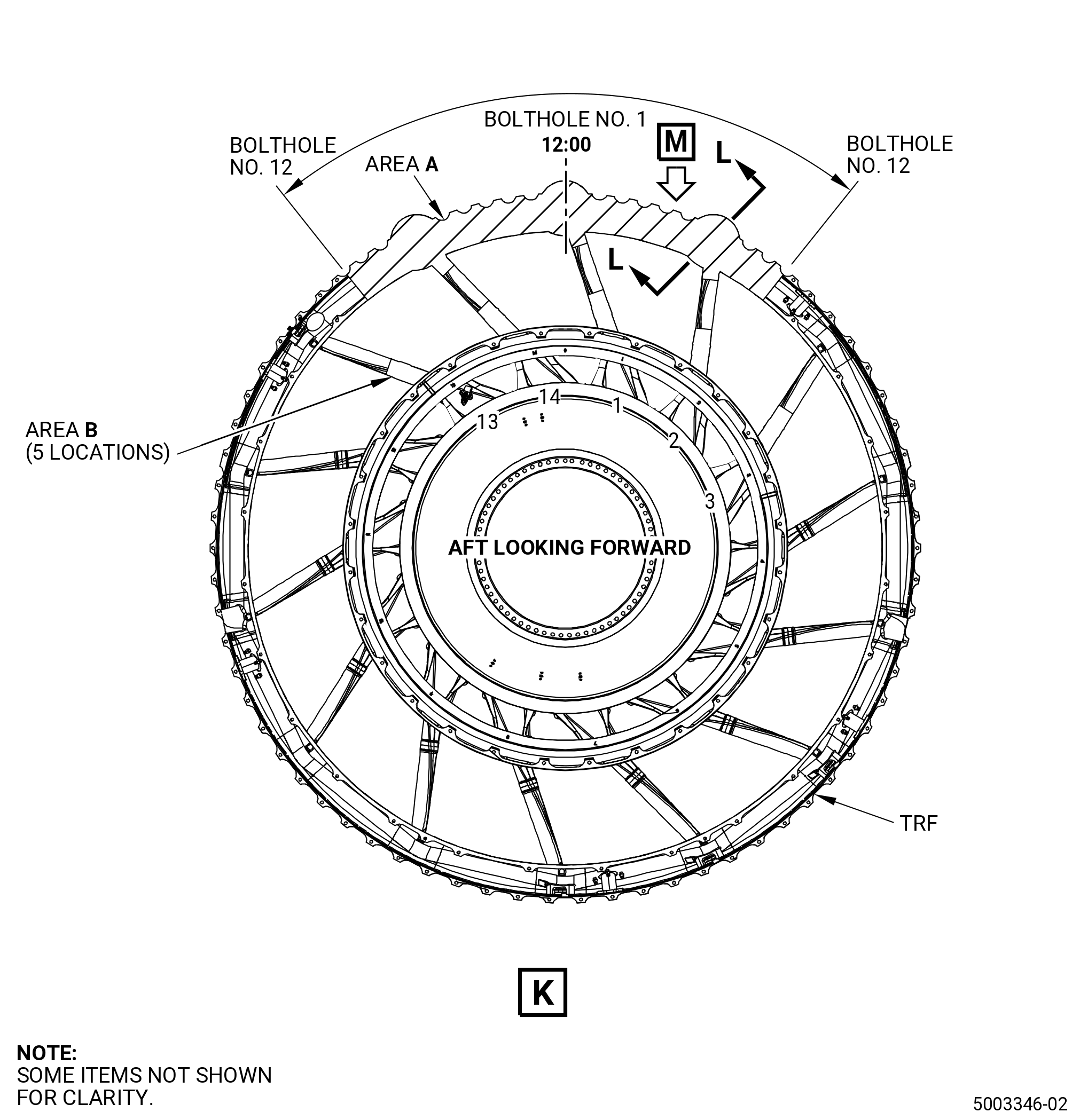
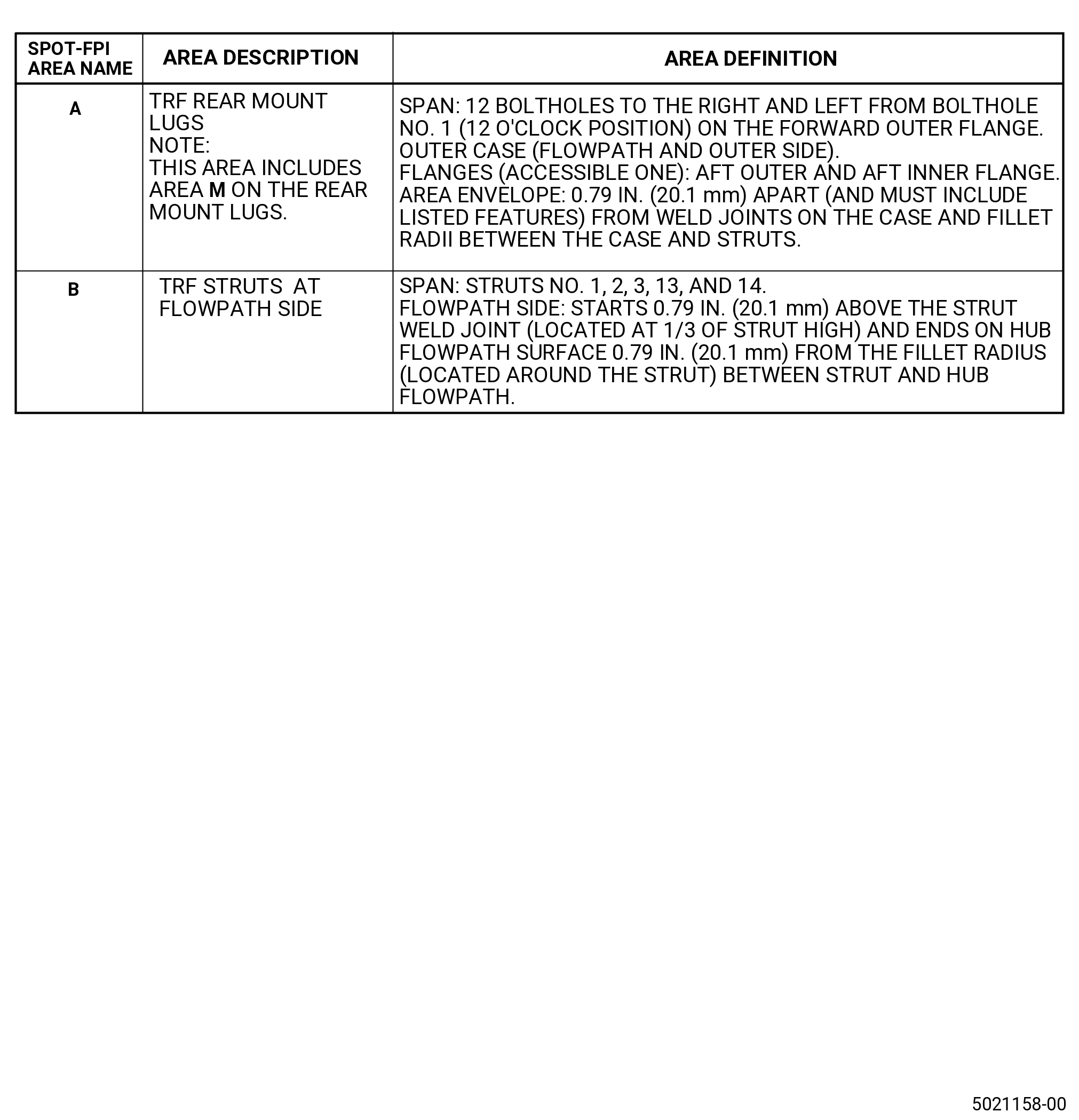
| A. | Do a Class C spot-fluorescent-penetrant inspection of the outer and inner surfaces of the TRF. Refer to Figure 803 and TASK 70-32-03-230-002 (SPOT-FLUORESCENT-PENETRANT INSPECTION). The limits must meet Class A (non welded parts) for structures and flanges and Class B (fusion welded parts) for welds. Refer to TASK 70-31-02-220-003 (ACCEPTABILITY LIMITS FOR FLUORESCENT-PENETRANT INSPECTION) and as follows: |
| (1) | Indications less than 0.03 inch (0.8 mm) are not interpretable and are permitted. |
| * * * END PRE SB 72-0160 |
| * * * END PRE SB 72-0138 |
| * * * END PRE SB 72-0063 |
| Subtask 72-00-57-230-002 |
| * * * SB 72-0063 |
| * * * SB 72-0138 |
| * * * SB 72-0160 |
| A.A. | Do a Class C spot-fluorescent-penetrant inspection of the outer and inner surfaces of the TRF. Refer to Figure 804 and TASK 70-32-03-230-002 (SPOT-FLUORESCENT-PENETRANT INSPECTION). The limits must align with Class A (non welded parts) for structures and flanges and Class B (fusion welded parts) for welds. Refer to TASK 70-31-02-220-003 (ACCEPTABILITY LIMITS FOR FLUORESCENT-PENETRANT INSPECTION) and as follows: |
| (1) | Indications less than 0.03 inch (0.8 mm) are not interpretable and are permitted. |
| * * * END SB 72-0160 |
| * * * END SB 72-0138 |
| * * * END SB 72-0063 |
| 4 . | Visual Inspection. |
| Subtask 72-00-57-220-001 |
| A. | Do an inspection of the outer surface of the outer case, without area A (rear mount lugs), of the TRF for. Refer to Figure 802. |
| (1) | Cracks in the parent material: |
| Maximum serviceable limit: |
|
| Repair method: |
|
| Subtask 72-00-57-220-053 |
| (2) | Cracks in the welds: |
| Maximum serviceable limit: |
|
| Repair method: |
|
| Subtask 72-00-57-220-012 |
| (3) | Nicks, scores, and scratches: |
| Maximum serviceable limit: |
|
| Maximum repairable limit: |
|
| Repair method: |
|
| Subtask 72-00-57-220-013 |
| (4) | Dents: |
| Maximum serviceable limit: |
|
| Maximum repairable limit: |
|
| Repair method: |
|
| Subtask 72-00-57-220-002 |
| B. | Do an inspection of the struts and airflow surfaces (hub airflow surface and outer case airflow surface), without area A (rear mount lugs) of the TRF. Refer to Figure 802 and as follows: |
| (1) | Cracks: |
| Maximum serviceable limit: |
|
| Repair method: |
|
| Subtask 72-00-57-220-014 |
| (2) | Nicks, scores, and scratches: |
| Maximum serviceable limit: |
|
| Repair method: |
|
| Subtask 72-00-57-220-015 |
| (3) | Dents on struts (struts No. 7 and No. 8 not included): |
| Maximum serviceable limit: |
|
| Repair method: |
|
| Subtask 72-00-57-220-054 |
| (4) | Dents on struts No. 7 and 8: |
| Maximum serviceable limit: |
|
| Repair method: |
|
| Subtask 72-00-57-220-039 |
| (5) | Dents on airflow surfaces (hub airflow surface and outer case airflow surface): |
| Maximum serviceable limit: |
|
| Maximum repairable limit: |
|
| Repair method: |
|
| Subtask 72-00-57-220-052 |
| (6) | Distortion of the hub lip (hub lip is not round or it is visually protruding to the flow path cavity): |
| Maximum serviceable limit: |
|
| Repair method: |
|
| Subtask 72-00-57-220-003 |
| C. | Do an inspection of the hub area of the TRF for: |
| (1) | Cracks: |
| Maximum serviceable limit: |
|
| Repair method: |
|
| Subtask 72-00-57-220-016 |
| (2) | Nicks, dents, scores, and scratches: |
| Maximum serviceable limit: |
|
| Maximum repairable limit: |
|
| Repair method: |
|
| Subtask 72-00-57-220-004 |
| D. | Do an inspection of the rear mount lugs described by area A (airflow side and outer surface side of the outer case) for. Refer to Figure 802. |
| (1) | Cracks in parent metal: |
| Maximum serviceable limit: |
|
| Repair method: |
|
| Subtask 72-00-57-220-055 |
| (2) | Cracks in the welds: |
| Maximum serviceable limit: |
|
| Repair method: |
|
| Subtask 72-00-57-220-056 |
| (3) | Circumferential scratches/scoring of the mount bushings: |
| Maximum serviceable limit: |
|
| Maximum repairable limit: |
|
| Repair method: |
|
| Subtask 72-00-57-220-017 |
| (4) | Axial scratches/scoring of the mount bushings: |
| Maximum serviceable limit: |
|
| Maximum repairable limit: |
|
| Repair method: |
|
| Subtask 72-00-57-220-018 |
| (5) | Deleted. |
| Subtask 72-00-57-220-040 |
| (6) | Bushing out of position: |
| Maximum serviceable limit: |
|
| Repair method: |
|
| Subtask 72-00-57-220-041 |
| (7) | Gouges, nicks, or dents located on the forward surface of the bushing shoulder of the center mount lugs. |
| Maximum serviceable limit: |
|
| Maximum repairable limit: |
|
| Repair method: |
|
| Subtask 72-00-57-220-042 |
| (8) | Gouges, nicks, or dents located on the forward surface of the bushings shoulder of the outer mount lugs. |
| Maximum serviceable limit: |
|
| Repair method: |
|
| Subtask 72-00-57-220-057 |
| (9) | Nicks, dents, scores, and scratches (area M not included): |
| Maximum serviceable limit: |
|
| Repair method: |
|
| Subtask 72-00-57-220-058 |
| (10) | Nicks, dents, scores, and scratches in area M: |
| Maximum serviceable limit: |
|
| Maximum repairable limit: |
|
| Repair method: |
|
| Subtask 72-00-57-220-059 |
| (11) | Circumferential scratches or scores on the forward surface of the forward lugs around mount bushings: |
| Maximum serviceable limit: |
|
| • |
|
| • |
|
| • |
|
| Maximum repairable limit: |
|
| • |
|
| • |
|
| • |
|
| Repair method: |
|
| Subtask 72-00-57-220-060 |
| (12) | Circumferential scratches or scores on the aft surface of the aft lugs around mount bushings: |
| Maximum serviceable limit: |
|
| • |
|
| • |
|
| • |
|
| Maximum repairable limit: |
|
| • |
|
| • |
|
| • |
|
| Repair method: |
|
| Subtask 72-00-57-220-005 |
| E. | Do an inspection of the No. 5 bearing inner stationary seal (01504) and the No. 5 bearing outer stationary seal (01559) for. Refer to Figure 802. |
| (1) | Cracks: |
| Maximum serviceable limit: |
|
| Repair method: |
|
| Subtask 72-00-57-220-020 |
| (2) | Rubs and grooves in the nickel graphite surface: |
| Maximum serviceable limit: |
|
| Repair method: |
|
| Subtask 72-00-57-220-021 |
| (3) | Missing coating: |
| Maximum serviceable limit: |
|
| Repair method: |
|
| Subtask 72-00-57-220-006 |
| F. | Do an inspection of the cone area of the TRF for. Refer to Figure 802. |
| (1) | Cracks in the parent material: |
| Maximum serviceable limit: |
|
| Repair method: |
|
| Subtask 72-00-57-220-022 |
| (2) | Cracks in the welds: |
| Maximum serviceable limit: |
|
| Repair method: |
|
| Subtask 72-00-57-220-023 |
| (3) | Nicks, scores, and scratches: |
| Maximum serviceable limit: |
|
| Maximum repairable limit: |
|
| Repair method: |
|
| Subtask 72-00-57-220-051 |
| (4) | Dents: |
| Maximum serviceable limit: |
|
| Repair method: |
|
| Subtask 72-00-57-220-007 |
| G. | Do an inspection of the forward outer flange of the TRF for. Refer to Figure 802. |
| (1) | Cracks (all areas): |
| Maximum serviceable limit: |
|
| Repair method: |
|
| Subtask 72-00-57-220-024 |
| (2) | Nicks, scores, and scratches: |
| Maximum serviceable limit: |
|
| Maximum repairable limit: |
|
| Repair method: |
|
| Subtask 72-00-57-220-025 |
| (3) | Dents: |
| Maximum serviceable limit: |
|
| Repair method: |
|
| Subtask 72-00-57-220-061 |
| (4) | Wear caused by Stage 7 LPT shrouds: |
| Maximum serviceable limit: |
|
| Repair method: |
|
| Subtask 72-00-57-220-026 |
| (5) | Distortion: |
| Maximum serviceable limit: |
|
| Repair method: |
|
| Subtask 72-00-57-220-008 |
| H. | Do an inspection of the aft outer flange of the TRF for. Refer to Figure 802. |
| (1) | Cracks (all areas): |
| Maximum serviceable limit: |
|
| Repair method: |
|
| Subtask 72-00-57-220-027 |
| (2) | Nicks, scores, and scratches: |
| Maximum serviceable limit: |
|
| Maximum repairable limit: |
|
| Repair method: |
|
| Subtask 72-00-57-220-028 |
| (3) | Dents: |
| Maximum serviceable limit: |
|
| Repair method: |
|
| Subtask 72-00-57-220-029 |
| (4) | Distortion: |
| Maximum serviceable limit: |
|
| Repair method: |
|
| Subtask 72-00-57-220-043 |
| I. | Do an inspection of the aft inner flange of the TRF for. Refer to Figure 802. |
| (1) | Cracks: |
| Maximum serviceable limit: |
|
| Repair method: |
|
| Subtask 72-00-57-220-044 |
| (2) | Nicks, dents, scores, and scratches (area X not included): |
| Maximum serviceable limit: |
|
| Maximum repairable limit: |
|
| Repair method: |
|
| Repair method: |
|
| Subtask 72-00-57-220-045 |
| (3) | Nicks, dents, scores, and scratches at area X: |
| Maximum serviceable limit: |
|
| Repair method: |
|
| Subtask 72-00-57-220-046 |
| (4) | Deformation: |
| Maximum serviceable limit: |
|
| Repair method: |
|
| Subtask 72-00-57-220-047 |
| (5) | Deleted. |
| Subtask 72-00-57-220-009 |
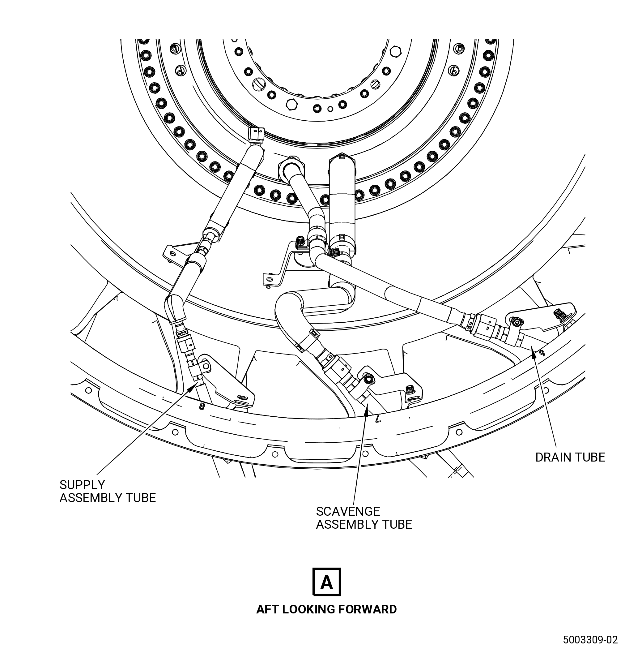
| J. | Do an inspection of the connector supply assembly tube (oil supply tube) (01-160 , 72-57-00) (SIN 443A0), the connector scavenge assembly tube (oil scavenge tube) (01-330 , 72-57-00) (SIN 452A0), and the connector drain assembly tube (vent drain tube) (01-520 , 72-57-00) (SIN 458A0) for. Refer to Figure 805. |
| (1) | Cracks: |
| Maximum serviceable limit: |
|
| Repair method: |
|
| Subtask 72-00-57-220-030 |
| (2) | Nicks, scores, and scratches: |
| Maximum serviceable limit: |
|
| Repair method: |
|
| Subtask 72-00-57-220-031 |
| (3) | Dents: |
| Maximum serviceable limit: |
|
| Repair method: |
|
| Subtask 72-00-57-220-032 |
| (4) | Internal coking: |
| Maximum serviceable limit: |
|
| Maximum repairable limit: |
|
| Repair method: |
|
| Subtask 72-00-57-220-062 |
| (5) | External coking: |
| Maximum serviceable limit: |
|
| Repair method: |
|
| Subtask 72-00-57-220-048 |
| (6) | Cuts or tears in the folded edges. Refer to Figure 805. |
| Maximum serviceable limit: |
|
| Repair method: |
|
| Subtask 72-00-57-220-049 |
| (7) | Torn or missing outer material of insulation blankets: |
| Maximum serviceable limit: |
|
| Repair method: |
|
| Subtask 72-00-57-220-050 |
| (8) | Missing retaining straps on the insulation blankets: |
| Maximum serviceable limit: |
|
| Repair method: |
|
| Subtask 72-00-57-220-038 |
| K. | Do an inspection of the supply assembly tube (01-170 , 72-57-00) (SIN 443A1), scavenge assembly tube (01-340 , 72-57-00) (SIN 452A1), and drain tube (01-530 , 72-57-00) (SIN 458A1) as follows. Refer to Figure 805. |
| (1) | Nicks, scratches, chafing, or scores in straight section and bends: |
| Maximum serviceable limit: |
|
| Repair method: |
|
| Subtask 72-00-57-220-063 |
| (2) | External coking: |
| Maximum serviceable limit: |
|
| Repair method: |
|
| Subtask 72-00-57-220-033 |
| (3) | Deleted. |
| Subtask 72-00-57-220-034 |
| (4) | Deleted. |
| Subtask 72-00-57-220-035 |
| (5) | Deleted. |
| Subtask 72-00-57-220-010 |
| L. | Do an inspection of the bracket assemblies (443E0, 443E1, 452E1, 458E0) and the air eductor tube bracket assembly for. Refer to Figure 805. |
| (1) | Cracks: |
| Maximum serviceable limit: |
|
| Repair method: |
|
| Subtask 72-00-57-220-011 |
| M. | Do an inspection of the eductor air tube for. Refer to Figure 805. |
| (1) | Cracks in all areas: |
| Maximum serviceable limit: |
|
| Repair method: |
|
| Subtask 72-00-57-220-036 |
| (2) | Nicks, scores, and scratches: |
| Maximum serviceable limit: |
|
| Repair method: |
|
| Subtask 72-00-57-220-037 |
| (3) | Dents: |
| Maximum serviceable limit: |
|
| Repair method: |
|