| GENX-1B CLEANING,INSPECTION,AND REPAIR MANUAL | Dated: 04/01/2021 | |
| CIR 72-58-40 , REPAIR 001 | ||
| LOW PRESSURE MID SHAFT ASSEMBLY - REPAIR - BALANCE INSPECTION AND IMBALANCE CORRECTION | ||
| GENX-1B CLEANING,INSPECTION,AND REPAIR MANUAL | Dated: 04/01/2021 | |
| CIR 72-58-40 , REPAIR 001 | ||
| LOW PRESSURE MID SHAFT ASSEMBLY - REPAIR - BALANCE INSPECTION AND IMBALANCE CORRECTION | ||
| * * * FOR ALL |
| TASK 72-58-40-300-801 |
| 1 . | Repair for the Low Pressure Mid Shaft Assembly. |
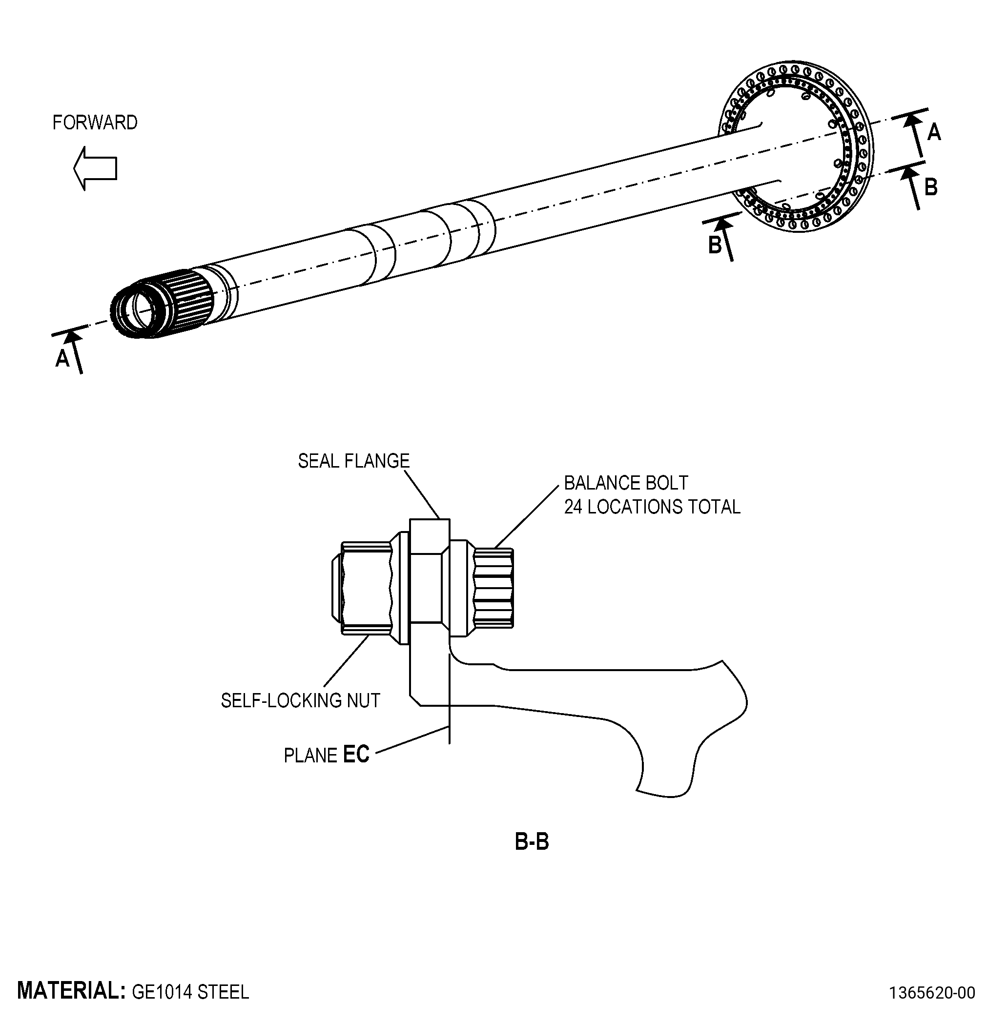
| A. | This procedure gives instructions to repair the mid fan shaft (shaft) by doing balance inspection and imbalance correction. Refer to Figure 901. |
| B. | There is no maximum repairable limit to apply to this repair. |
| C. | The subsequent table gives a list of the part numbers that are applicable to this repair. All part numbers are applicable to all paragraphs unless specified differently. |
|
|||||||||||||||||||||||||||||||||||||||||||||||||
| D. | Proprietary/Complex Process Statement. |
| (1) | None. |
| 2 . | Tools, Equipment, and Materials. |
| NOTE: |
|
| A. | Tools and Equipment. |
| (1) | Special Tools. None. |
| (2) | Standard Tools and Equipment. |
|
| (3) | Locally Manufactured Tools. None. |
| B. | Consumable Materials. |
| C. | Referenced Procedures. |
|
| D. | Expendable Parts. None. |
| E. | SPD Information. |
|
| (1) | Locally Manufactured SPD. None. |
| F. | Special Solutions. None. |
| G. | Test Specimens. None. |
| 3 . | Dimensional Information. |
| Subtask 72-58-40-220-070 |
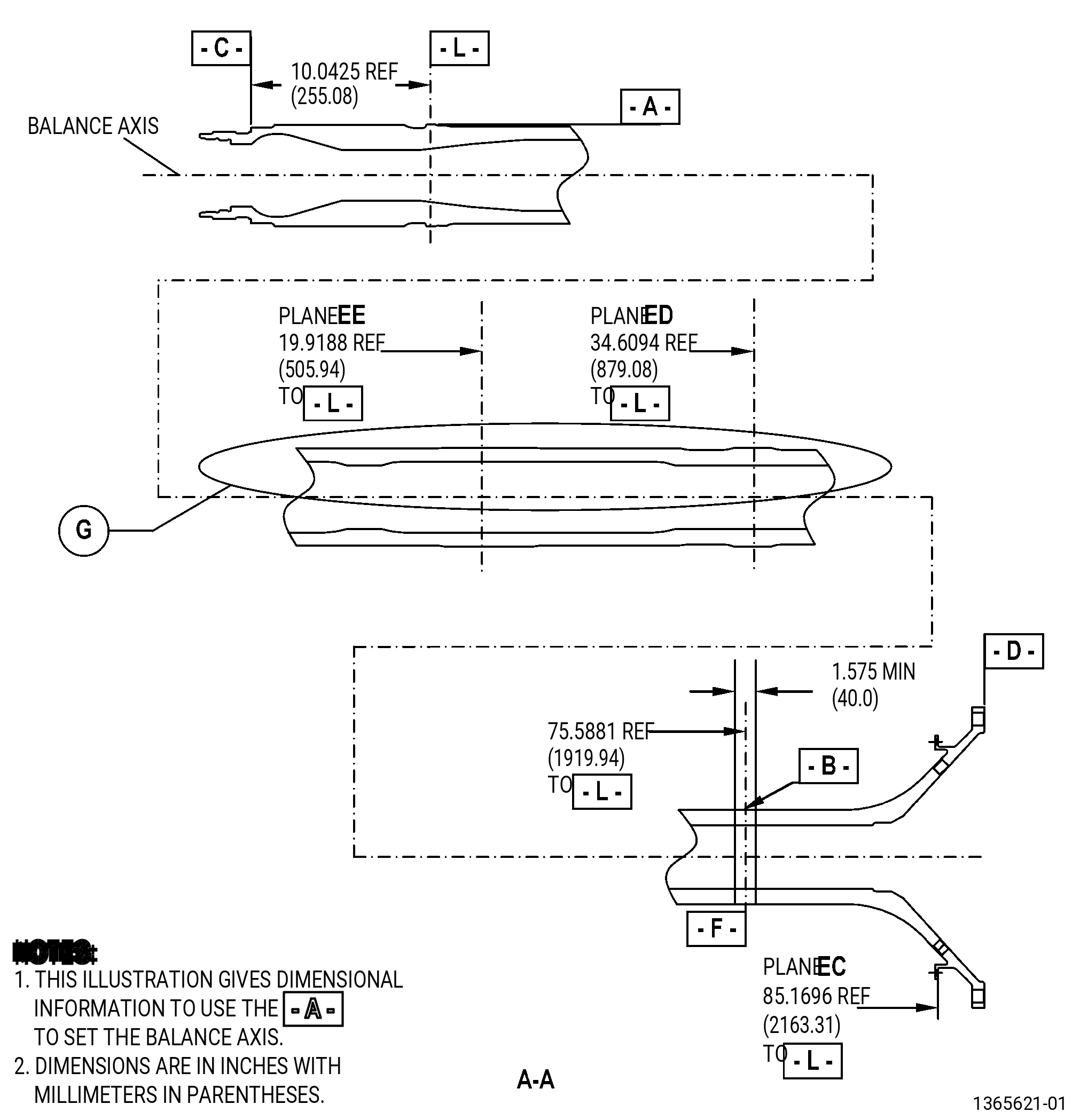
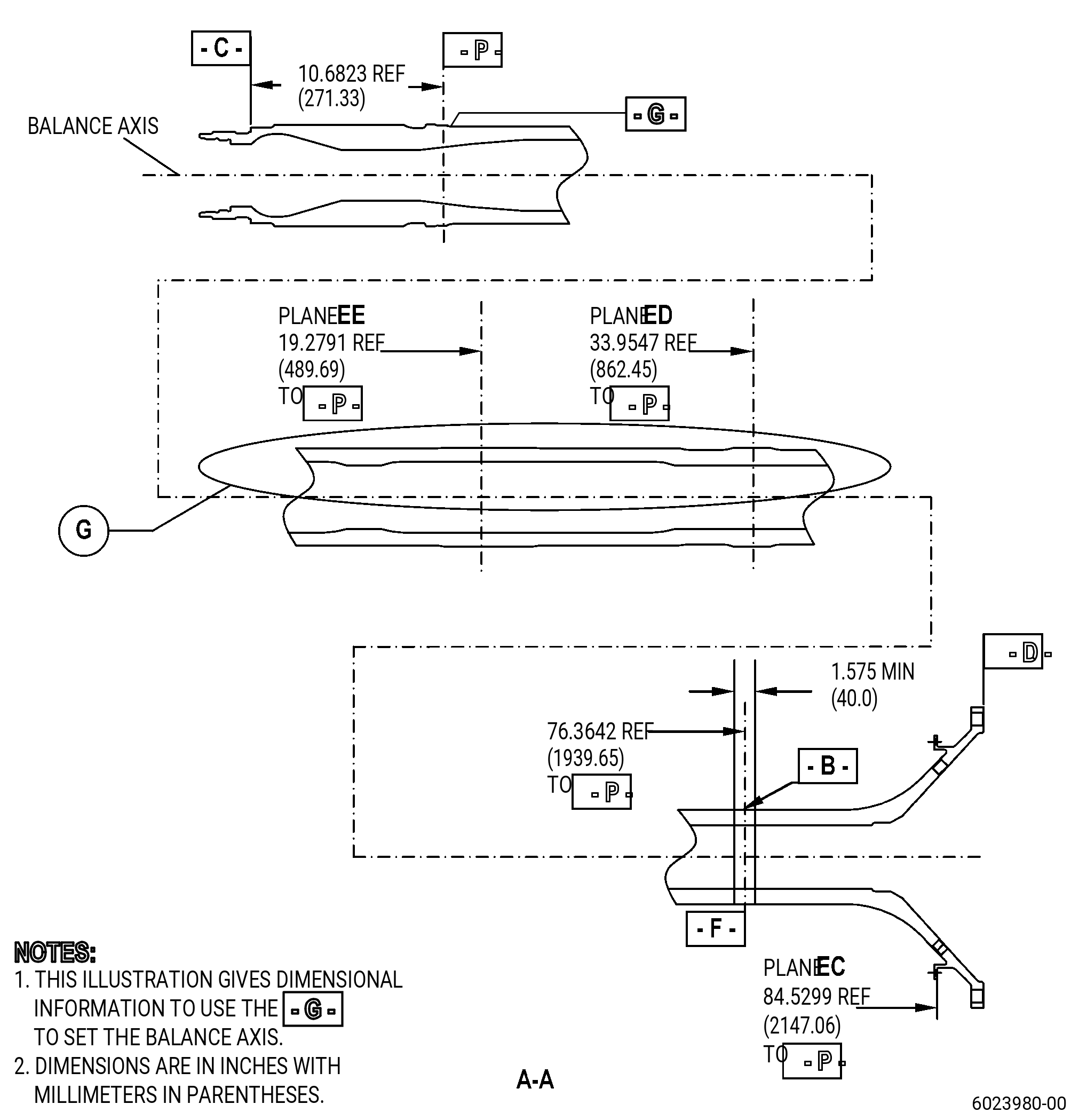
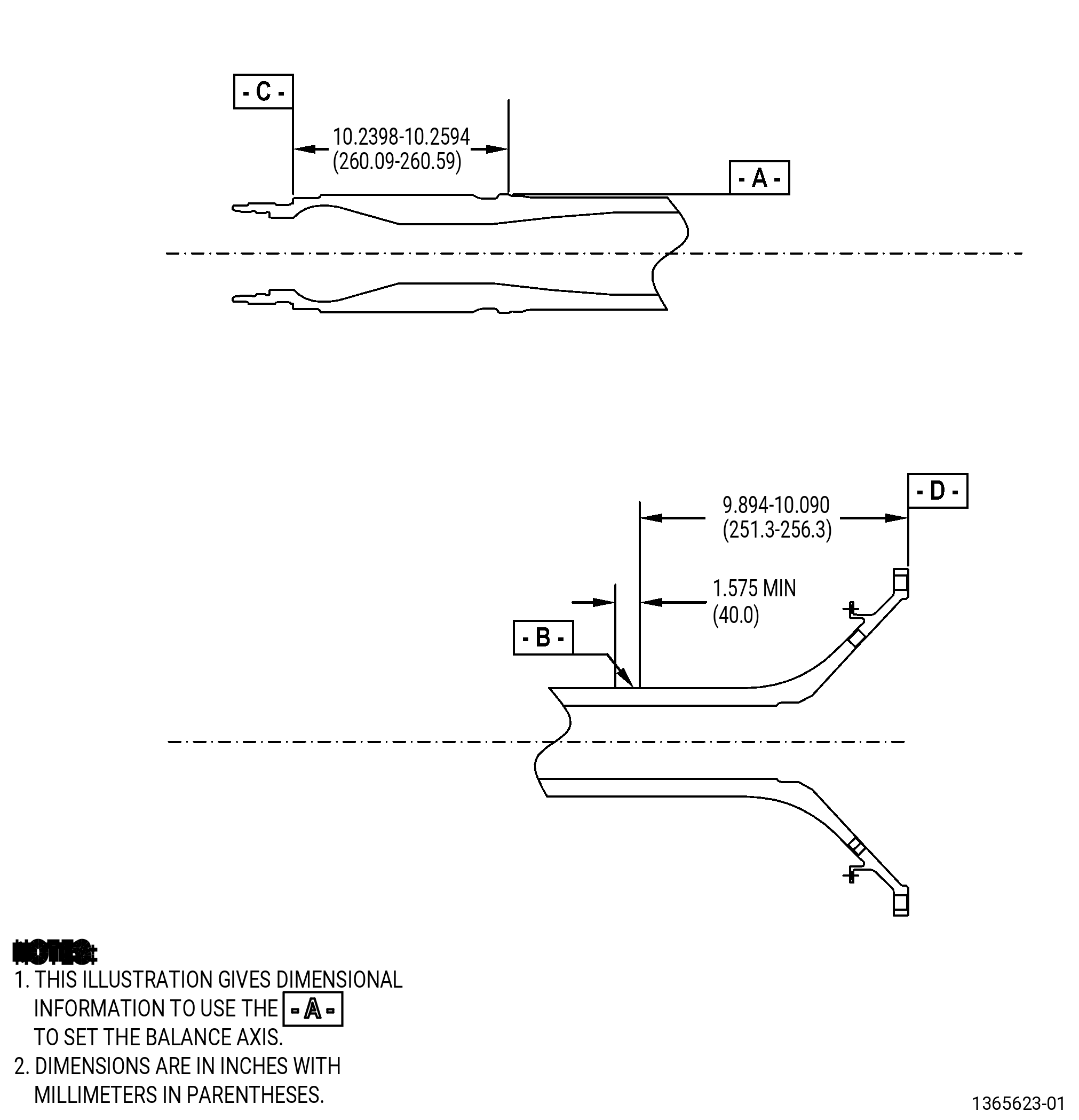
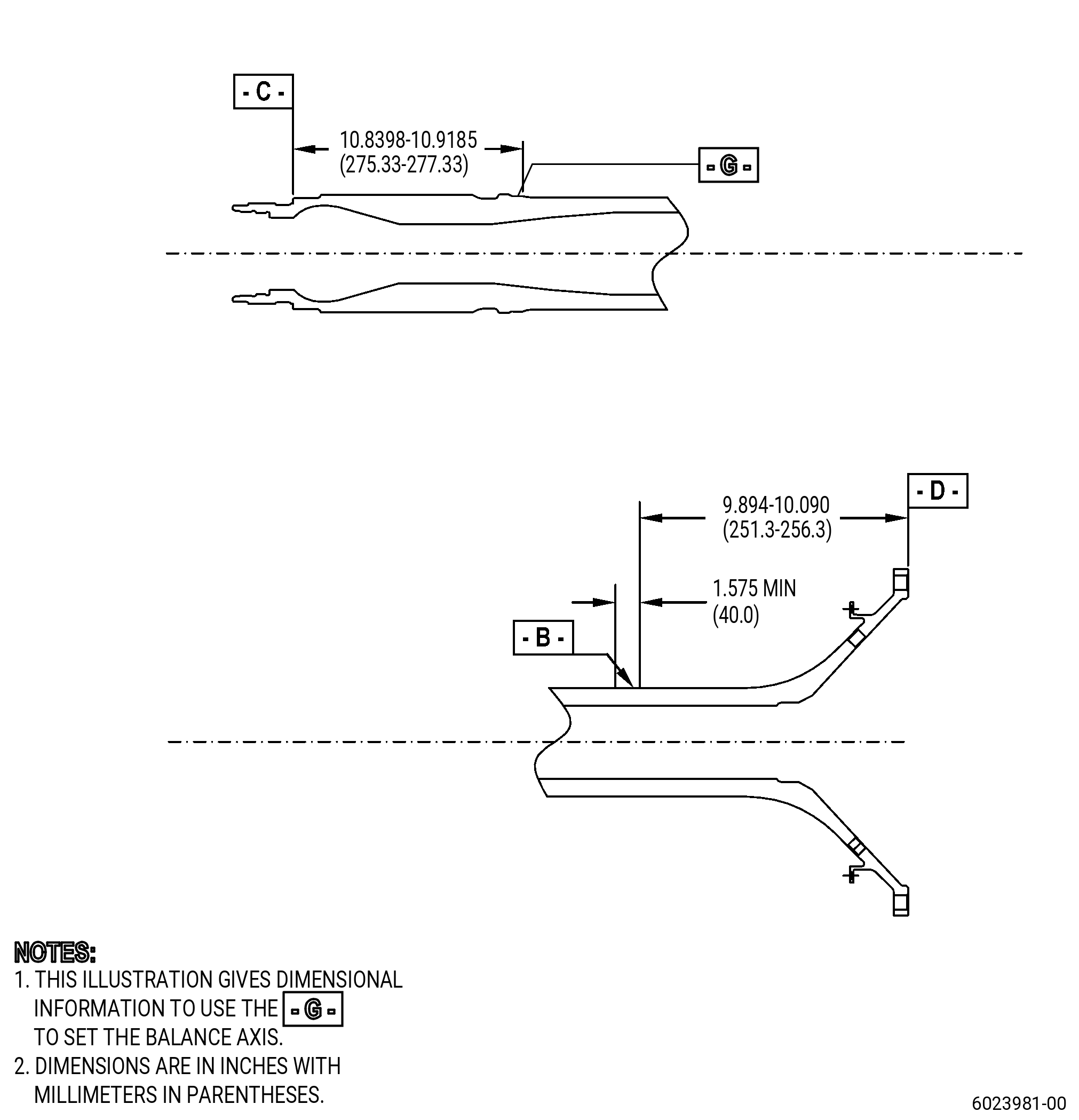
| A. | Refer to Figure 901 and Figure 902 for specified dimensions and locations. |
| NOTE: |
|
| NOTE: |
|
| 4 . | Setup Information. |
| Subtask 72-58-40-350-001 |
| A. | Set-up the shaft for balance measurement. Refer to Figure 902 and as follows: |
| (1) | Use a balancing machine that can turn the shaft at a speed of 330-640 rpm. |
| (2) | Use datum A or datum G and datum B to set the balance axis. |
| (3) | Turn the shaft in the balancing machine at the specified speed for a minimum of 15 minutes before you do the measurements. |
| 5 . | Procedure. |
| Subtask 72-58-40-220-071 |
| A. | Do a static balance inspection of the shaft as follows: |
| (1) | Set-up the shaft for balance measurement. Refer to Subtask 72-58-40-350-001 (paragraph 4.A.), Setup Information. |
| (2) | Set the rotation speed to 330-640 rpm. |
| (3) | Record the imbalance absolute value and direction. The maximum absolute value permitted is 106.29 g-in (2700 g-mm). |
| Subtask 72-58-40-350-002 |
| (4) | If necessary, put a mark on the shaft to show the location and direction of imbalance. Refer to TASK 70-16-00-350-001 (MARKING PRACTICES), TASK 70-16-02-350-017 (TEMPORARY MARKING), and as follows: |
| (a) | Use C05-003 marking pen. |
| (5) | If imbalance correction is necessary, go to Subtask 72-58-40-350-003 (paragraph 5.B.). If it is not necessary, go to Subtask 72-58-40-220-073 (paragraph 5.C.). |
| Subtask 72-58-40-350-003 |
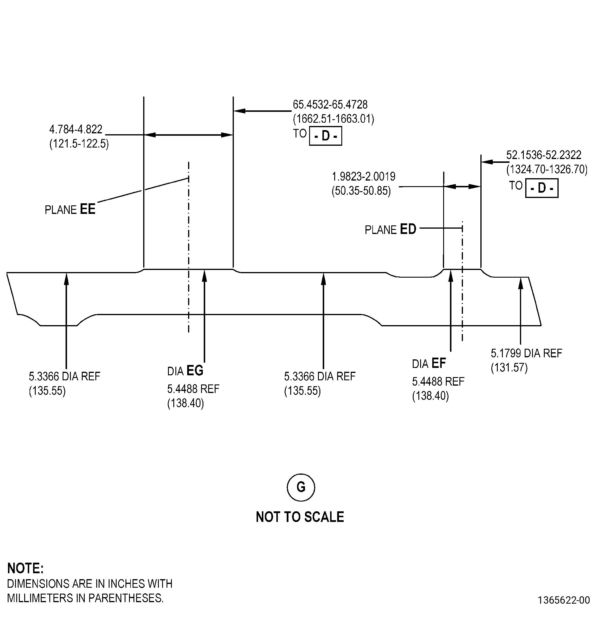
| B. | Do an imbalance correction of the shaft at diameter EF. Refer to Figure 902 and as follows: |
| NOTE: |
|
| (1) | If necessary, apply C10-021 plastic tape to mask the surfaces adjacent to diameter EF. |
| Subtask 72-58-40-320-001 |
| WARNING: |
|
| (2) | Alternative Procedure Available. Machine the shaft to remove material at diameter EF. Refer to TASK 70-00-03-800-004 (MACHINING DATA) and as follows: |
| (a) | Do not do concave machining. |
| Subtask 72-58-40-350-004 |
| (2).A. | Alternative Procedure. Blend the shaft to remove material at diameter EF. Refer to TASK 70-42-00-350-002 (BLENDING AND REMOVAL OF HIGH METAL PROCEDURES) and as follows: |
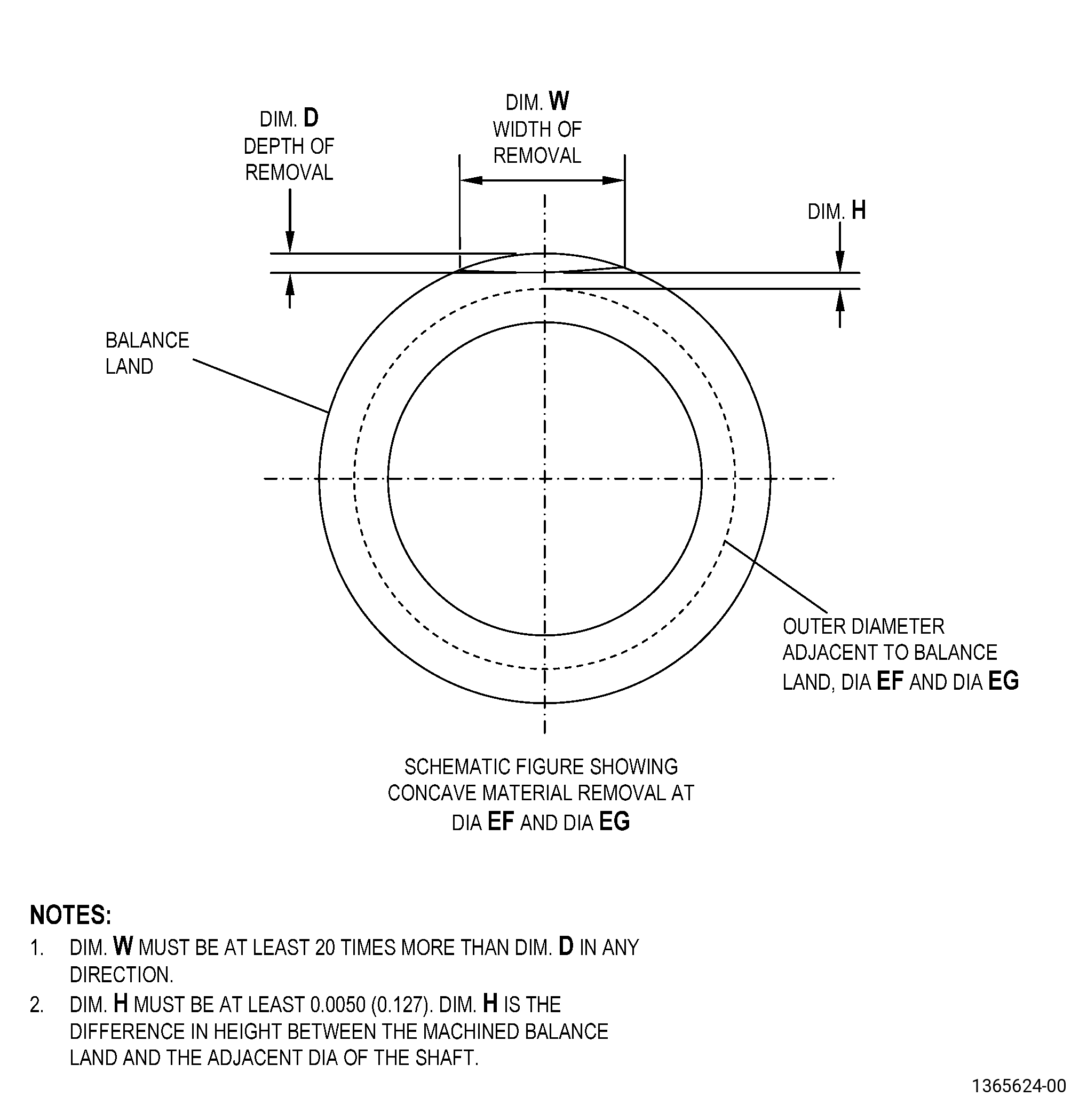
| (a) | If you do concave blending, the width of removal in all directions must be a minimum of 20 times greater than the depth of the removal. |
| (3) | The surface finish of the repaired surface must be 63 microinches (1.6 micrometers) or better. |
| (4) | The finished dimension of diameter EF must be a minimum of 0.0050 inch (0.13 mm) above the adjacent shaft diameter. |
| (5) | Break all sharp edges to 0.00500-0.01500 inch (0.127-0.381 mm). Refer to TASK 70-42-00-350-002 (BLENDING AND REMOVAL OF HIGH METAL PROCEDURES). |
| (6) | Remove the plastic tape. |
| Subtask 72-58-40-220-072 |
| (7) | Do Subtask 72-58-40-220-071 (paragraph 5.A.) again to do a static balance inspection. |
| Subtask 72-58-40-220-073 |
| C. | Do a dynamic balance inspection of the shaft as follows: |
| (1) | Set-up the shaft for balance measurement. Refer to Subtask 72-58-40-350-001 (paragraph 4.A.), Setup Information. |
| (2) | Set the inspection plane to plane EC and plane EE. |
| (3) | Set the rotation speed at 330-640 rpm. |
| (4) | Record the imbalance absolute value and direction. The maximum absolute value permitted is 6.20 g-in (158 g-mm). |
| Subtask 72-58-40-350-005 |
| (5) | If necessary, put a mark on the shaft to show the location and direction of imbalance. Refer to Refer to TASK 70-16-00-350-001 (MARKING PRACTICES), TASK 70-16-02-350-017 (TEMPORARY MARKING), and as follows: |
| (a) | Use C05-003 marking pen. |
| Subtask 72-58-40-350-006 |
| D. | If necessary, do an imbalance correction of the shaft at plane EE. Refer to Figure 902 and as follows: |
| NOTE: |
|
| (1) | If necessary, apply C10-021 plastic tape to mask the surfaces adjacent to diameter EG. |
| Subtask 72-58-40-320-002 |
| WARNING: |
|
| (2) | Alternative Procedure Available. Machine the shaft to remove material at diameter EG. Refer to TASK 70-00-03-800-004 (MACHINING DATA) and as follows: |
| (a) | Do not do concave machining. |
| Subtask 72-58-40-350-007 |
| (2).A. | Alternative Procedure. Blend the shaft to remove material at diameter EG. Refer to TASK 70-42-00-350-002 (BLENDING AND REMOVAL OF HIGH METAL PROCEDURES) and as follows: |
| (a) | If you do concave blending, the width of removal in all directions must be a minimum of 20 times greater than the depth of the removal. |
| (3) | The surface finish of the repaired surface must be 63 microinches (1.6 micrometers) or better. |
| (4) | The finished dimension of diameter EG must be a minimum of 0.005 inch (0.13 mm) above the adjacent shaft diameter. |
| (5) | Break all sharp edges to 0.00500-0.01500 inch (0.127-0.381 mm). Refer to TASK 70-42-00-350-002 (BLENDING AND REMOVAL OF HIGH METAL PROCEDURES). |
| (6) | Remove the plastic tape. |
| Subtask 72-58-40-350-008 |
| E. | If necessary, do an imbalance correction of the shaft at plane EC. Refer to Figure 901, Figure 902, and as follows: |
| NOTE: |
|
| Subtask 72-58-40-110-006 |
| (1) | Use C04-035 isopropyl alcohol to clean the boltholes before you install the bolt. |
| Subtask 72-58-40-220-074 |
| (2) | Do a visual inspection of the boltholes as follows: |
| (a) | Use 10X magnification and white light. |
| (b) | Indications are not permitted. |
| Subtask 72-58-40-110-014 |
| (3) | If you are using the balance bolts and nuts again, clean them. Refer to TASK 70-21-00-110-051 (CHEMICAL CLEANING), TASK 70-21-03-160-001 (CLEANING METHOD NO. 3 - STEAM CLEANING), TASK 70-21-06-110-004 (CLEANING METHOD NO. 6 - HEAVY-DUTY ALKALINE CLEANER (WITHOUT INHIBITED PHOSPHORIC ACID)), TASK 70-21-22-110-801 (CLEANING METHOD NO. 22 - LIGHT DUTY AQUEOUS CLEANING), and TASK 70-21-23-110-053 (CLEANING METHOD NO. 23 - HAND-WIPE DEGREASING). |
| NOTE: |
|
| Subtask 72-58-40-350-009 |
| (4) | Install or remove balance bolt, J644P06A, and self-locking nut, J1092P04, where necessary to correct the imbalance, and do as follows: |
| (a) | Apply C02-023 engine oil or C02-097 lubricant to the nut threads and bearing face before you install them into the flange. |
| (5) | Torque the balance bolt to 110 to 120 lb in. (12.5 to 13.5 Nm). |
| Subtask 72-58-40-220-075 |
| F. | Do Subtask 72-58-40-220-073 (paragraph 5.C.) again to do a dynamic balance inspection. |
| Subtask 72-58-40-220-076 |
| G. | Do a visual inspection of the shaft repaired areas as follows: |
| (1) | Use a minimum of 10X magnification and white light. |
| (2) | Indications are not permitted. |
| Subtask 72-58-40-220-077 |
| H. | Do a visual inspection of the shaft datum A or datum G and datum B as follows: |
| (1) | Use white light and a minimum of 10X magnification. |
| (2) | Missing, peeling, and loose coating are not permitted. |
| Subtask 72-58-40-380-001 |
| I. | Alternative Procedure Available. Peen the shaft repaired areas. Refer to TASK 70-47-01-380-016 (SHOTPEENING) and as follows: |
| (1) | Use C04-271 S170 cast steel shot. |
| (2) | Use an intensity of 10-15A. |
| (3) | A minimum of 100 percent coverage, fade out to adjacent peened surfaces, is necessary. |
| (4) | Use C10-110 almen test strips and almen strip holder to verify the intensity at the shaft repaired areas. |
| Subtask 72-58-40-380-002 |
| I.A. | Alternative Procedure. Peen the shaft repaired areas. Refer to TASK 70-47-04-380-019 (ROTARY FLAP PEENING) and as follows: |
| (1) | The maximum flapper shot size must be S330 or equivalent. |
| (2) | Use an intensity of 14-21A (converted value for magnetic almen holder). |
| (3) | A minimum of 100 percent coverage, fade out to adjacent peened surfaces is necessary. |
| (4) | Use C10-110 almen test strips and almen strip holder to verify the intensity at the shaft repaired areas. |
| Subtask 72-58-40-380-003 |
| J. | Surface-treat the shaft repaired areas, as follows: |
| (1) | For part numbers 2331M20G02 , 2331M20G03 , 2332M81G01 , 2332M81G03 , and 2332M81G04 , refer to TASK 70-43-05-380-005 (INORGANIC ALUMINUM PROTECTIVE COATING) and do as follows: |
| (a) | Use only the C03-039 touch up paint and the touch up procedure specified. |
| (b) | Apply C03-039 touch up paint to datum A or datum G and datum B, if necessary. |
| (c) | Three coats are required. Overlap to adjacent painted area is necessary for full coverage. Bare metal is not permitted. |
| (2) | For part numbers 2332M81G05 , 2440M20G05 , 2440M91G05 , and 2440M91G06 , refer to TASK 72-58-40-300-812 (72-58-40, REPAIR 013). |