| GENX-1B CLEANING,INSPECTION,AND REPAIR MANUAL | Dated: 04/30/2015 | |
| CIR 72-58-45 , REPAIR 002 | ||
| NO. 4 BEARING AFT ROTATING SEAL - REPAIR - REPLACEMENT OF NICKEL-GRAPHITE COATING | ||
| GENX-1B CLEANING,INSPECTION,AND REPAIR MANUAL | Dated: 04/30/2015 | |
| CIR 72-58-45 , REPAIR 002 | ||
| NO. 4 BEARING AFT ROTATING SEAL - REPAIR - REPLACEMENT OF NICKEL-GRAPHITE COATING | ||
| * * * FOR ALL |
| TASK 72-58-45-300-801 |
| 1 . | Replacement of Nickel-Graphite Coating. |
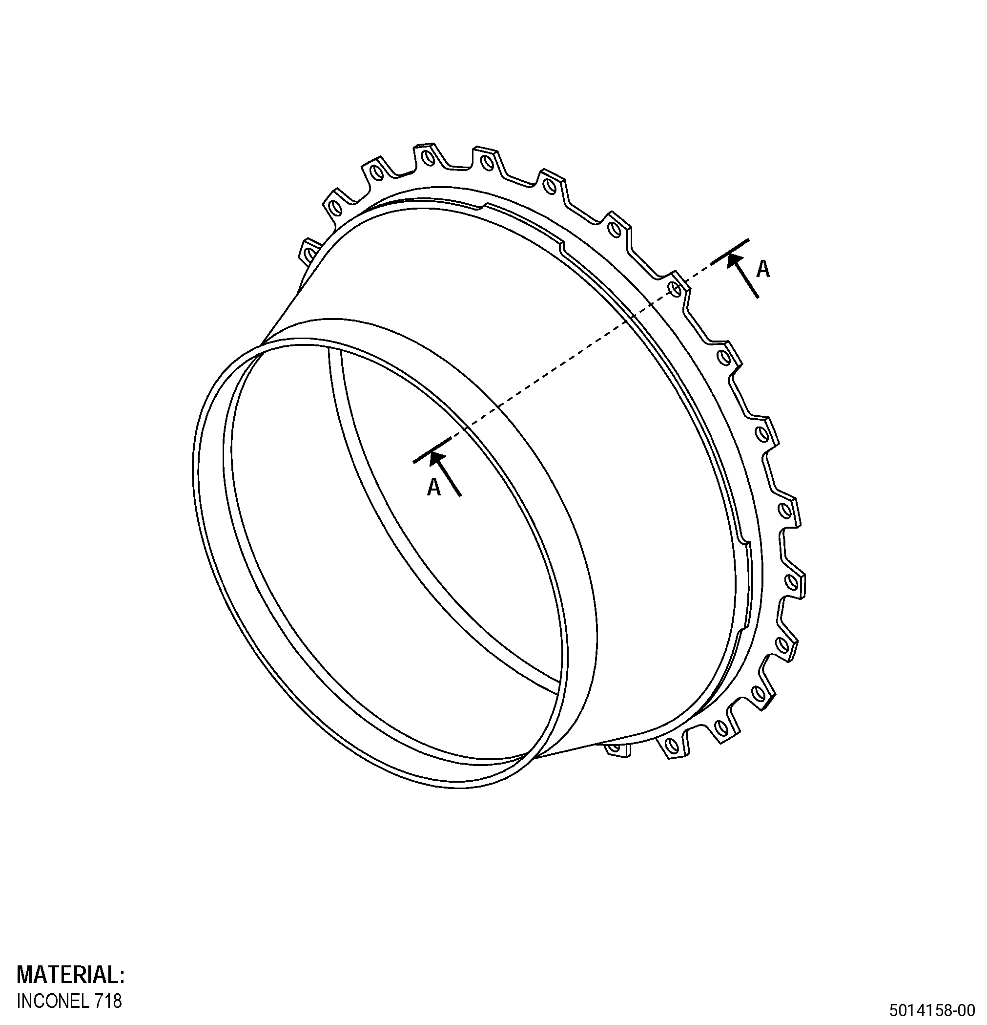
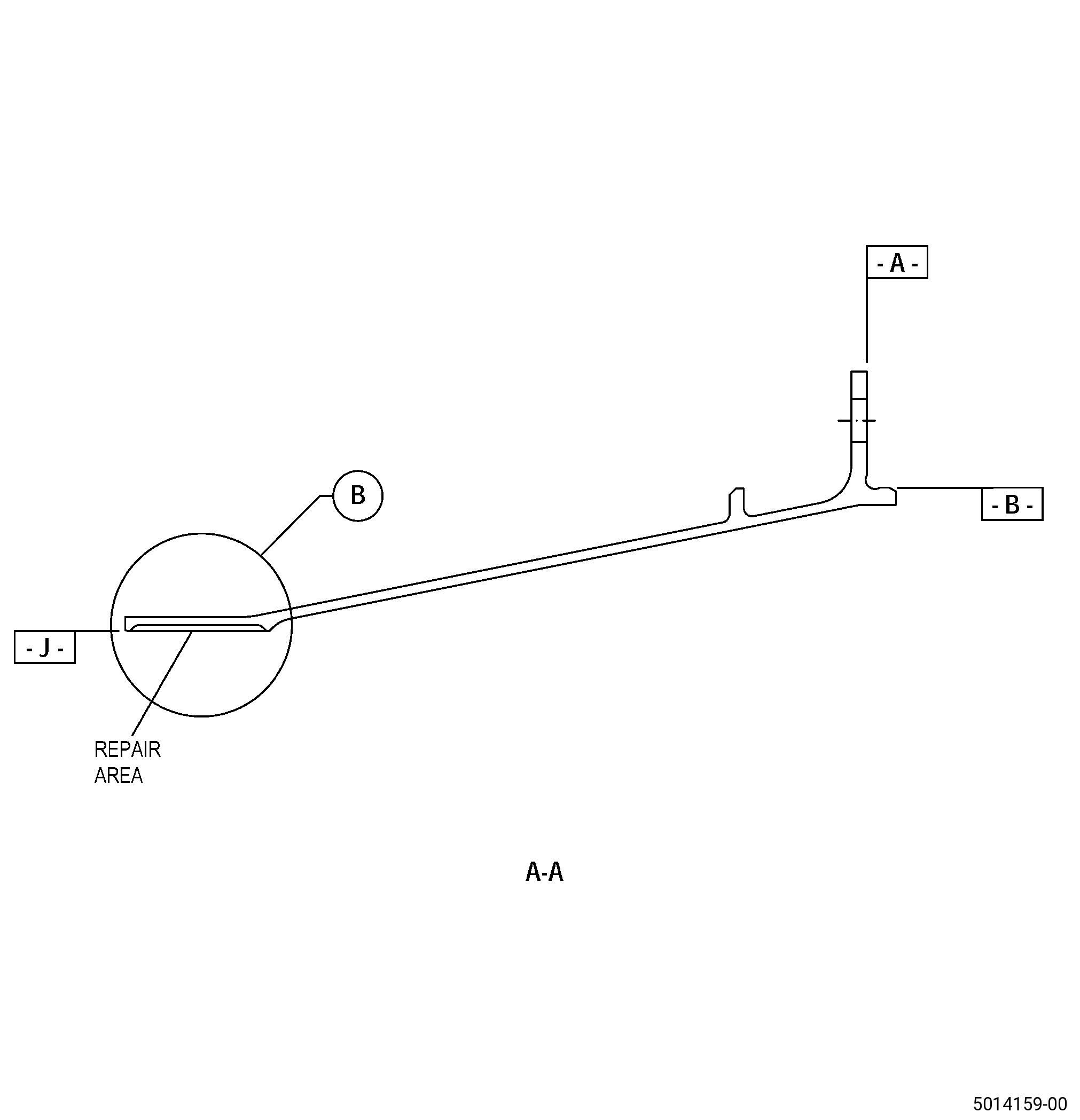
| A. | This procedure gives instructions to repair the No. 4 bearing aft rotating seal (seal) by removing and replacing the nickel-graphite coating. Refer to Figure 901. |
| B. | The following maximum repairable limits apply to this repair: |
| NOTE: |
|
| NOTE: |
|
| (4) | Visual Inspection. |
| (b) | Do an inspection of the coating in area L for: |
| 1 | Rubs or grooves: |
| Maximum repairable limit: |
|
| 2 | Missing coating: |
| Maximum repairable limit: |
|
| C. | The subsequent table gives a list of the part numbers that are applicable to this repair. All part numbers are applicable to all paragraphs unless specified differently. |
|
|||||||||||||||||||||||
| D. | Proprietary/Complex Process Statement. |
| (1) | None. |
| 2 . | Tools, Equipment, and Materials. |
| NOTE: |
|
| A. | Tools and Equipment. |
| (1) | Special Tools. None. |
| (2) | Standard Tools and Equipment. None. |
| (3) | Locally Manufactured Tools. |
|
| B. | Consumable Materials. |
|
| C. | Referenced Procedures. |
| D. | Expendable Parts. None. |
| E. | SPD Information. |
| (1) | Locally Manufactured SPD. None |
| F. | Special Solutions. None. |
| G. | Test Specimens. Refer to TASK 70-49-10-340-011 (THERMAL SPRAYING NICKEL-ALUMINUM (POWDER)) , TASK 70-49-11-340-012 (THERMAL SPRAYING NICKEL-ALUMINUM (WIRE)) , and TASK 70-49-15-340-016 (THERMAL SPRAYING 85:15 NICKEL-GRAPHITE (POWDER)) . |
| 3 . | Dimensional Information. |
| Subtask 72-58-45-220-021 |
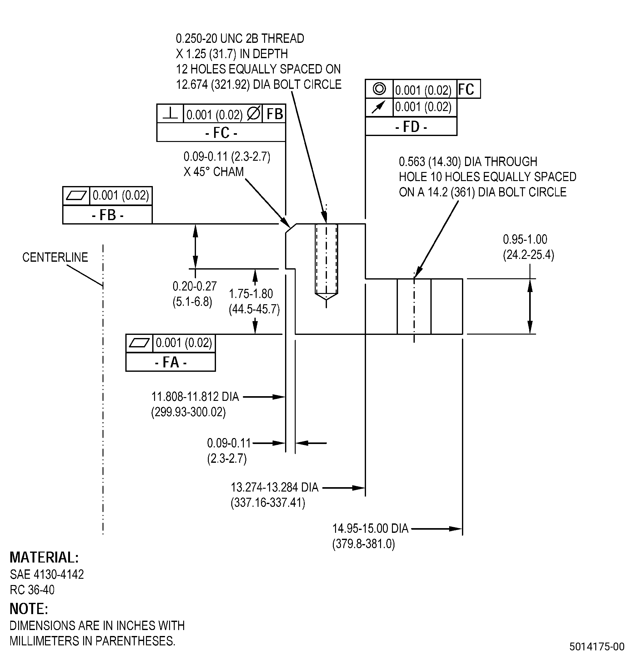
| A. | Refer to Figure 901 for specified dimensions and locations. |
| NOTE: |
|
| NOTE: |
|
| 4 . | Setup Information. |
| Subtask 72-58-45-350-001 |
| A. | Set-up the seal for machining. Refer to Figure 901, Figure 903, and as follows: |
| Subtask 72-58-45-930-001 |
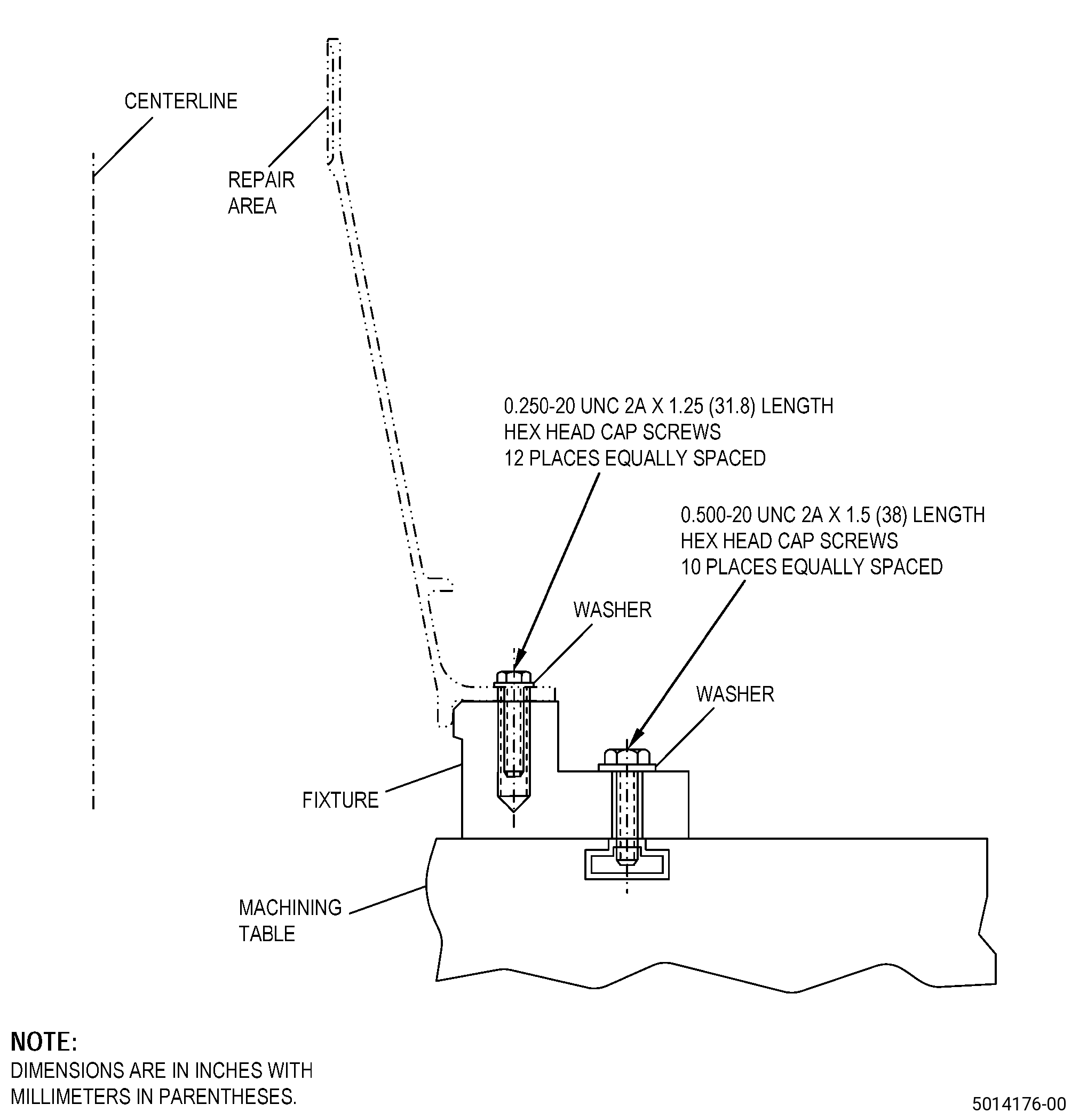
| (1) | If necessary, make the machining fixture. Refer to Figure 902. |
| Subtask 72-58-45-350-002 |
| (2) | Install the machining fixture on the machine table. Refer to Figure 902 and as follows: |
| Subtask 72-58-45-220-022 |
| (a) | The runout of the machining fixture diameter FC must be 0.001 inch (0.02 mm) or less. |
| (b) | The runout of the machining fixture surface FB must be 0.001 inch (0.02 mm) or less. |
| Subtask 72-58-45-350-003 |
| (3) | Install the seal on the machining fixture as follows: |
| (a) | Make sure that the seal aft side points down. |
| Subtask 72-58-45-370-001 |
| (b) | If necessary, decrease the temperature of the seal to install it on the machining fixture. |
| Subtask 72-58-45-350-004 |
| (c) | Use the machining fixture diameter FD to do a check of the runout of the seal diameter B and as follows: |
| Subtask 72-58-45-220-023 |
| 1 | The runout of the machining fixture diameter FD must be less than 0.001 inch (0.02 mm). |
| Subtask 72-58-45-350-005 |
| (d) | Use the machining fixture diameter FD to do a check of the runout of the seal diameter K and as follows: |
| Subtask 72-58-45-220-024 |
| 1 | The runout of diameter K must be 0.005 inch (0.12 mm) or less. |
| 5 . | Procedure. |
| Subtask 72-58-45-160-004 |
| A. | Clean the seal. Refer to TASK 70-21-00-110-051 (CHEMICAL CLEANING) and TASK 70-21-03-160-001 (CLEANING METHOD NO. 3 - STEAM CLEANING). |
| Subtask 72-58-45-120-001 |
| B. | Alternative Procedure Available. Remove the nickel-graphite top coating and the nickel-aluminum bond coating from the seal as follows: |
| (1) | Apply C10-012 masking tape to all areas that are external to the thermal spray coating area. Refer to Figure 904. |
| (2) | Clean the seal to remove the nickel-graphite top coating. Refer to TASK 70-21-04-120-001 (CLEANING METHOD NO. 4 - DRY ABRASIVE BLAST CLEANING) and as follows: |
| (a) | Use Method 4E. |
| (3) | Remove the masking tape from the seal. |
| Subtask 72-58-45-160-003 |
| WARNING: |
|
| (4) | Use clean, dry, oil-free compressed shop air to clean the seal. |
| (5) | Apply C10-012 masking tape to all areas that are external to the thermal spray coating area. Refer to Figure 904. |
| Subtask 72-58-45-110-011 |
| (6) | Remove the nickel-aluminum bond coating from the seal. Refer to TASK 70-23-00-100-001 (STRIPPING PROCEDURES) and TASK 70-23-08-110-024 (STRIPPING OF PURE ALUMINUM AND NICKEL-ALUMINUM BOND COATINGS). |
| (7) | Remove the masking tape from the seal. |
| Subtask 72-58-45-330-002 |
| B.A. | Alternative Procedure. Remove the nickel-graphite top coating and the nickel-aluminum bond coating from the seal. Refer to TASK 70-23-00-100-001 (STRIPPING PROCEDURES) and TASK 70-23-23-330-008 (REMOVAL OF COATINGS BY HIGH PRESSURE WATER STRIPPING). |
| Subtask 72-58-45-320-002 |
| CAUTION: |
|
| B.B. | Alternative Procedure. Machine the seal to remove the nickel-graphite top coating and the nickel-aluminum bond coating. Refer to TASK 70-00-03-800-004 (MACHINING DATA), Subtask 72-58-45-220-021 (paragraph 3.A.), Figure 901, and as follows: |
| NOTE: |
|
| Subtask 72-58-45-350-006 |
| (1) | Set-up the seal for machining. Refer to Subtask 72-58-45-350-001 (paragraph 4.A.). |
| (2) | Machine diameter J to the in-process dimensions. |
| (3) | Remove the seal from the machining fixture. |
| Subtask 72-58-45-220-025 |
| C. | Measure the seal diameter J. Refer to Subtask 72-58-45-220-021 (paragraph 3.A.), Figure 901, and as follows: |
| (1) | If diameter J agrees with the in-process dimensions, do Subtask 72-58-45-110-012 (paragraph 5.D.) thru Subtask 72-58-45-160-005 (paragraph 5.M.). |
| (2) | If there is remaining thermal spray coating and diameter J is less than the maximum in-process dimension, do Subtask 72-58-45-120-001 (paragraph 5.B.) again. |
| (3) | If diameter J is more than the maximum in-process dimension, you cannot repair the seal with this procedure. |
| Subtask 72-58-45-110-012 |
| D. | Etch the exposed seal parent material in the thermal spray coating area. Refer to TASK 70-24-00-110-033 (ETCHING PROCEDURES FOR FLUORESCENT-PENETRANT INSPECTION), TASK 70-24-01-110-034 (SWAB ETCHING PROCEDURE), Figure 901, and as follows: |
| (1) | Use Class C etchant. |
| Subtask 72-58-45-230-003 |
| E. | Do an inspection of the seal repair area. Refer to TASK 70-32-00-200-002 (INDIRECT INSPECTION METHODS), TASK 70-32-03-230-002 (SPOT-FLUORESCENT-PENETRANT INSPECTION), Figure 901, and as follows: |
| (1) | Make sure that you remove all the thermal spray coating from the seal before you do the fluorescent penetrant inspection. |
| NOTE: |
|
| (2) | Use Class G penetrant. |
| (3) | Indications are permitted as follows: |
| (a) | They are a minimum of 0.50 inch (12.7 mm) apart. |
| (b) | They are a maximum of 0.03 inch (0.7 mm) in length. |
| (c) | They are 0.03-0.06 inch (0.8-1.5 mm) in length and are not interpreted as linear indications. |
| NOTE: |
|
| Subtask 72-58-45-340-001 |
| F. | Alternative Procedure Available. Thermal-spray the seal and the test specimens. Refer to TASK 70-49-00-340-001 (THERMAL SPRAYING), TASK 70-49-10-340-011 (THERMAL SPRAYING NICKEL-ALUMINUM (POWDER)), Figure 901, Figure 904, and as follows: |
| (1) | Apply C10-012 masking tape to the seal areas that you will not thermal-spray. |
| (2) | Make sure that you do the preliminary operations specified in TASK 70-49-00-340-001 (THERMAL SPRAYING). |
| (a) | Use the surface roughness limits for the nickel base material. |
| Subtask 72-58-45-360-001 |
| (3) | Apply the bond coating to the seal and the test specimens to a thickness of 0.004-0.008 inch (0.11-0.20 mm) and as follows: |
| (a) | Make sure that you apply thermal spray coating to the test specimens at the same time, same spray angle, and to the same thickness as the seal. |
| (4) | Overspray is not permitted. |
| Subtask 72-58-45-340-002 |
| (5) | Do all the quality assurance testing specified in TASK 70-49-10-340-011 (THERMAL SPRAYING NICKEL-ALUMINUM (POWDER)). |
| Subtask 72-58-45-340-003 |
| F.A. | Alternative Procedure. Thermal-spray the seal and the test specimens. Refer to TASK 70-49-00-340-001 (THERMAL SPRAYING), TASK 70-49-11-340-012 (THERMAL SPRAYING NICKEL-ALUMINUM (WIRE)), Figure 901, Figure 904, and as follows: |
| (1) | Apply C10-012 masking tape to the seal areas that you will not thermal-spray. |
| (2) | Make sure that you do the preliminary operations specified in TASK 70-49-00-340-001 (THERMAL SPRAYING). |
| (a) | Use the surface roughness limits for the nickel base material. |
| Subtask 72-58-45-360-002 |
| (3) | Apply the bond coating to the seal and the test specimens to a thickness of 0.004-0.008 inch (0.11-0.20 mm) and as follows: |
| (a) | Make sure that you apply thermal spray coating to the test specimens at the same time, same spray angle, and to the same thickness as the seal. |
| (4) | Overspray is not permitted. |
| Subtask 72-58-45-340-004 |
| (5) | Do all the quality assurance testing specified in TASK 70-49-11-340-012 (THERMAL SPRAYING NICKEL-ALUMINUM (WIRE)). |
| Subtask 72-58-45-340-005 |
| CAUTION: |
|
| G. | Thermal-spray the seal and the test specimens. Refer to TASK 70-49-00-340-001 (THERMAL SPRAYING), TASK 70-49-15-340-016 (THERMAL SPRAYING 85:15 NICKEL-GRAPHITE (POWDER)), Subtask 72-58-45-220-021 (paragraph 3.A.), Figure 901, and as follows: |
| (1) | If necessary, apply C10-012 masking tape again to the areas that you will not thermal-spray. |
| (2) | Apply the top coating to the seal and the test specimens to a maximum as-sprayed thickness of 0.085 inch (2.15 mm) and to a sufficient thickness to machine the seal to the finish dimensions and as follows: |
| (a) | Make sure that you apply thermal spray coating to the test specimens at the same time, same spray angle, and to the same thickness as the seal. |
| (3) | Overspray is not permitted. |
| (4) | Do all the quality assurance testing specified in TASK 70-49-15-340-016 (THERMAL SPRAYING 85:15 NICKEL-GRAPHITE (POWDER)). |
| (5) | Carefully remove the masking tape from the seal. |
| Subtask 72-58-45-110-013 |
| H. | Clean the seal to remove all the remaining masking tape. Refer to TASK 70-21-00-110-051 (CHEMICAL CLEANING) and TASK 70-21-23-110-053 (CLEANING METHOD NO. 23 - HAND-WIPE DEGREASING). |
| Subtask 72-58-45-340-006 |
| I. | If the test specimens do not agree with the requirements specified in Subtask 72-58-45-340-001 (paragraph 5.F.) and/or Subtask 72-58-45-340-005 (paragraph 5.G.), do Subtask 72-58-45-160-004 (paragraph 5.A.) thru Subtask 72-58-45-110-013 (paragraph 5.H.) again. |
| Subtask 72-58-45-320-001 |
| J. | Machine the seal repair area to the finish dimensions. Refer to TASK 70-00-03-800-004 (MACHINING DATA), Subtask 72-58-45-220-021 (paragraph 3.A.), Figure 901, and as follows: |
| Subtask 72-58-45-350-007 |
| (1) | Set-up the seal for machining. Refer to Subtask 72-58-45-350-001 (paragraph 4.A.). |
| (2) | Machine diameter J to the finish dimensions. |
| (3) | Remove the seal from the machining fixture. |
| Subtask 72-58-45-350-008 |
| K. | If necessary, lightly blend the seal to remove all the irregular edges between the masking area and the thermal spray coating area. Refer to TASK 70-42-00-350-002 (BLENDING AND REMOVAL OF HIGH METAL PROCEDURES). |
| Subtask 72-58-45-220-026 |
| L. | Do a visual inspection of the thermal spray coating surface of the seal and do as follows: |
| (1) | Lumps (berries), flaking, cracks, blisters, voids, and/or spattered particles of material that are unbonded or not atomized are not permitted. |
| NOTE: |
|
| Subtask 72-58-45-160-005 |
| M. | Clean the seal. Refer to TASK 70-21-00-110-051 (CHEMICAL CLEANING) and TASK 70-21-03-160-001 (CLEANING METHOD NO. 3 - STEAM CLEANING). |