| GENX-1B CLEANING,INSPECTION,AND REPAIR MANUAL | Dated: 10/14/2024 | |
| CIR 72-31-42 , INSPECTION 001 | ||
| HPC STAGE 2 BLISK - INSPECTION | ||
| GENX-1B CLEANING,INSPECTION,AND REPAIR MANUAL | Dated: 10/14/2024 | |
| CIR 72-31-42 , INSPECTION 001 | ||
| HPC STAGE 2 BLISK - INSPECTION | ||
| * * * FOR ALL |
| TASK 72-31-42-200-801 |
| 1 . | General. |
| A. | This procedure gives instructions to do an inspection of the high pressure compressor (HPC) stage 2 blisk (blisk): |
| • |
|
| • |
|
| • |
|
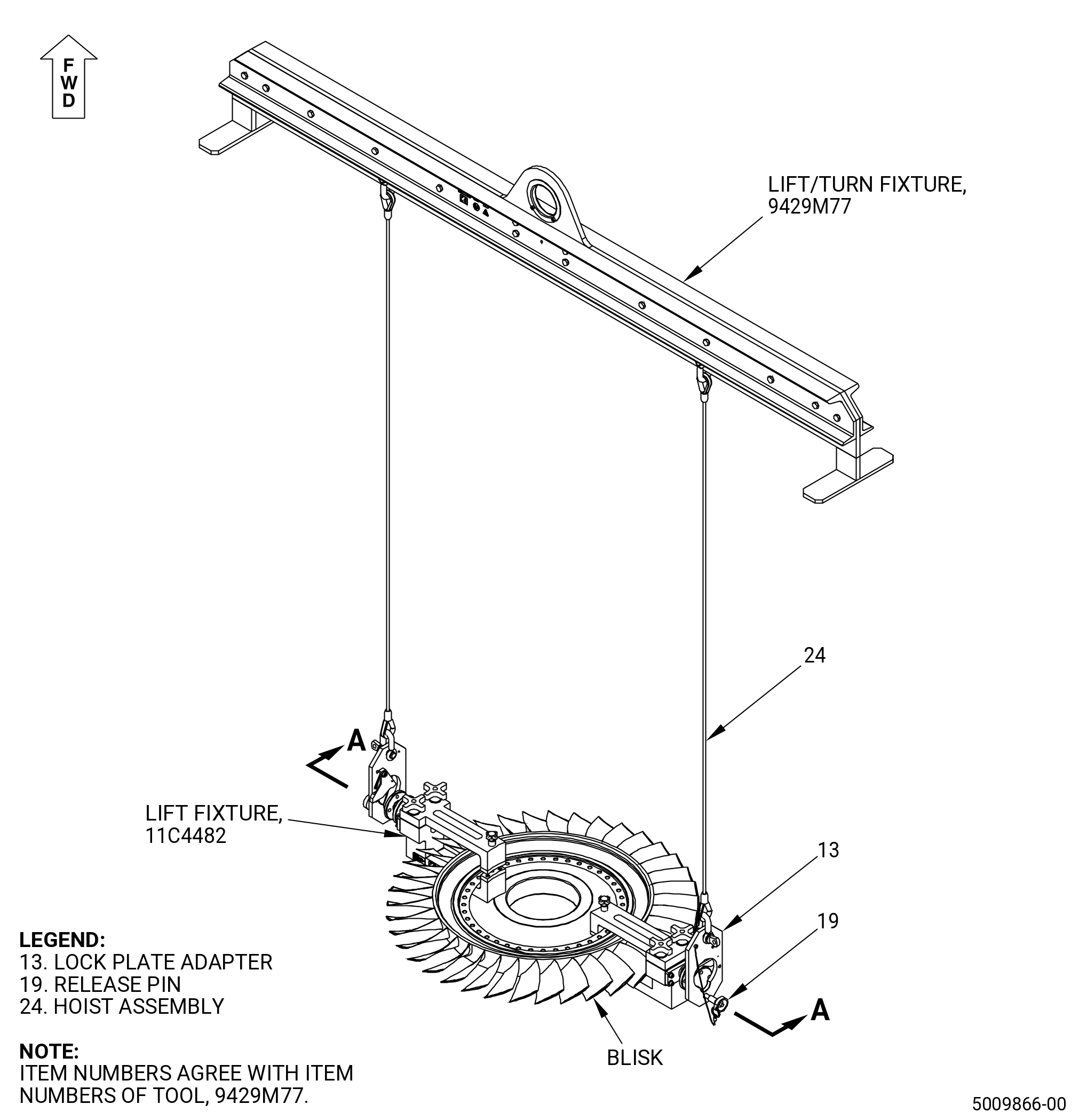
| B. | Use the 11C4482 lift fixture to position, lift, or turn the blisk in the working area. Refer to Subtask 72-31-42-420-001 (paragraph 3.A.) for instructions about installation and removal of the tool. |
| 2 . | Tools, Equipment, and Materials. |
| NOTE: |
|
| A. | Tools and Equipment. |
| (1) | Special Tools. |
|
| (2) | Standard Tools and Equipment. |
| (3) | Locally Manufactured Tools. None. |
| B. | Consumable Materials. |
|
| C. | Referenced Procedures. |
|
| D. | Expendable Parts. None. |
| 3 . | Tool Installation and Removal. |
| Subtask 72-31-42-420-001 |
| A. | Install the 11C4482 lift fixture. Refer to Figure 801 and do as follows: |
| (1) | Turn the knobs (item 15) and screw knobs (item 5) counterclockwise (CCW) to make sure that the supports (item 12) are open. |
| (2) | Install the supports (item 12) on the blisk. |
| (3) | Install the clamps (item 13) on the other side of the blisk. |
| (4) | Make sure that the clamps (item 13) are aligned with the supports (item 12). |
| (5) | Tighten the screw knobs (item 5) to set the supports (item 12) and hand-tighten the knobs (item 15) clockwise (CW) until the supports (item 12) and clamps (item 13) are tightly held in place. |
| (6) | Install the 9429M77 lift/turn fixture as follows: |
| (a) | Put the lock plate adapter (item 13) on the trunnion (item 6) and attach it with the release pin (item 19). |
| (7) | Use the 9429M77 lift/turn fixture to move the 11C4482 lift fixture. |
| Subtask 72-31-42-020-001 |
| B. | Remove the 11C4482 lift fixture. Refer to Figure 801 and do as follows: |
| (1) | Remove the 9429M77 lift/turn fixture from the 11C4482 lift fixture as follows: |
| (a) | Remove the release pin (item 19) and lock plate adapter (item 13) from the 11C4482 lift fixture. |
| (2) | Turn the knobs (item 15) and the screw knobs (item 5) CCW to open the set of supports (item 12) and clamps (item 13). |
| (3) | Remove the 11C4482 lift fixture from the blisk. |
| 4 . | Specific Inspection Procedure. |
| NOTE: |
|
| Subtask 72-31-42-230-001 |
| WARNING: |
|
| WARNING: |
|
| A. | Do a Class G non-aqueous wet developer fluorescent penetrant inspection of the blisk. Refer to TASK 70-32-02-230-001 (FLUORESCENT PENETRANT INSPECTION). |
| (1) | Make sure you do a careful inspection of the critical areas that follows: |
| • |
|
| • |
|
| • |
|
| • |
|
| (2) | Indications 0.015 inch (0.38 mm) or less are permitted. |
| Subtask 72-31-42-250-001 |
| B. | Do an eddy current inspection of the blisk boltholes as follows. Refer to Figure 802. |
| Subtask 72-31-42-160-002 |
| CAUTION: |
|
| (1) | Make sure that the boltholes are clean. Refer to 72-31-42-100-801 (72-31-42, CLEANING 001) and TASK 70-22-06-110-043 (SPECIAL CLEANING PROCEDURE 6 - BOLTHOLE CLEANING FOR EDDY CURRENT INSPECTION). |
| NOTE: |
|
| Subtask 72-31-42-250-002 |
| (2) | Do an eddy current inspection of the boltholes as follows. Refer to TASK 70-32-07-250-001 (HIGH SPEED AND SLOW SPEED EDDY CURRENT INSPECTION OF CIRCULAR HOLES IN INCONEL OR TITANIUM ENGINE PARTS). |
| NOTE: |
|
| (a) | (a) If you change the equipment or the procedure specified in this inspection, it can have an unwanted effect on the inspection results. Before you change the equipment or the procedure, write to: |
| GE Aircraft Engines, OTC |
| One Neumann Way, MD: Q8 |
| Cincinnati, Ohio 45215 |
| USA |
| (b) | Do an inspection of the boltholes as follows: |
| 1 | Use the GE-FQAP-605 inspection kit with either the GE-FQAP-302 inspection kit, GE-FQAP-302A inspection kit, GE-FQAP-302B inspection kit, or GE- FQAP-302C inspection kit. |
| 2 | Use the filter settings that follow: |
| • |
|
| • |
|
| • |
|
| • |
|
| • |
|
| • |
|
| • |
|
| 3 | The calibration amplitude is four divisions, peak to peak. |
| (c) | Complete the eddy current data sheets. If eddy current indications are found that are equal to or greater than four major divisions, the stage 2 blisk is not serviceable. |
| (d) | Make sure that all records made during the eddy current inspection are as complete as possible. Keep all records made during the inspection. |
| Subtask 72-31-42-250-003 |
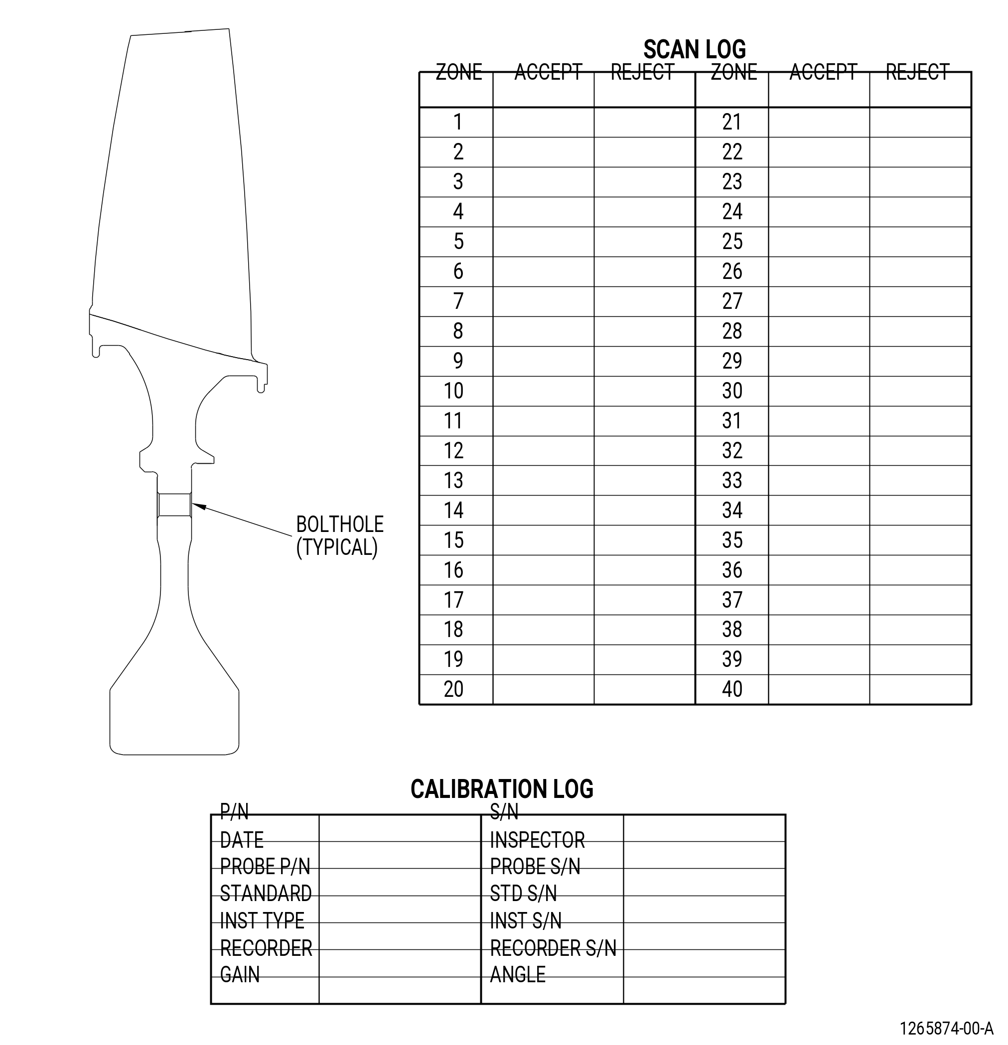
| C. | Do an eddy current inspection of the blisk bores as follows. Refer to Figure 803. |
| Subtask 72-31-42-100-001 |
| (1) | Clean the blisk bore. Refer to TASK 72-31-42-100-801 (72-31-42, CLEANING 001). |
| Subtask 72-31-42-250-004 |
| (2) | Do an eddy current inspection of the blisk bore surfaces. Refer to TASK 70-32-10-250-003 (2 MHZ EDDY CURRENT INSPECTION OF BORES IN ROTATING ENGINE HARDWARE USING SYSTEMS UNDER COMPUTER, NUMERIC, OR ROBOTIC CONTROL). |
| NOTE: |
|
| NOTE: |
|
| NOTE: |
|
| (a) | Inspect the bore areas shown in the scan plan. |
| (b) | Complete the eddy current data sheets. Refer to Figure 804. |
| (c) | Eddy current inspection evaluation limit is 1500 mV. |
| (d) | Eddy current inspection reject limit is 1500 mV after evaluation is completed. |
| (e) | All blisks that are rejected by the limit in Subtask 72-31-42-250-004 (paragraph 3.C.(2)(d)) are not serviceable. |
| (f) | All blisks that are not rejected by the limits in Subtask 72-31-42-250-004 (paragraph 3.C.(2)(d)) are serviceable. |
| (g) | Make sure that all records made during the eddy current inspection are as complete as possible. Permanently keep these records for each blisk that was inspected. |
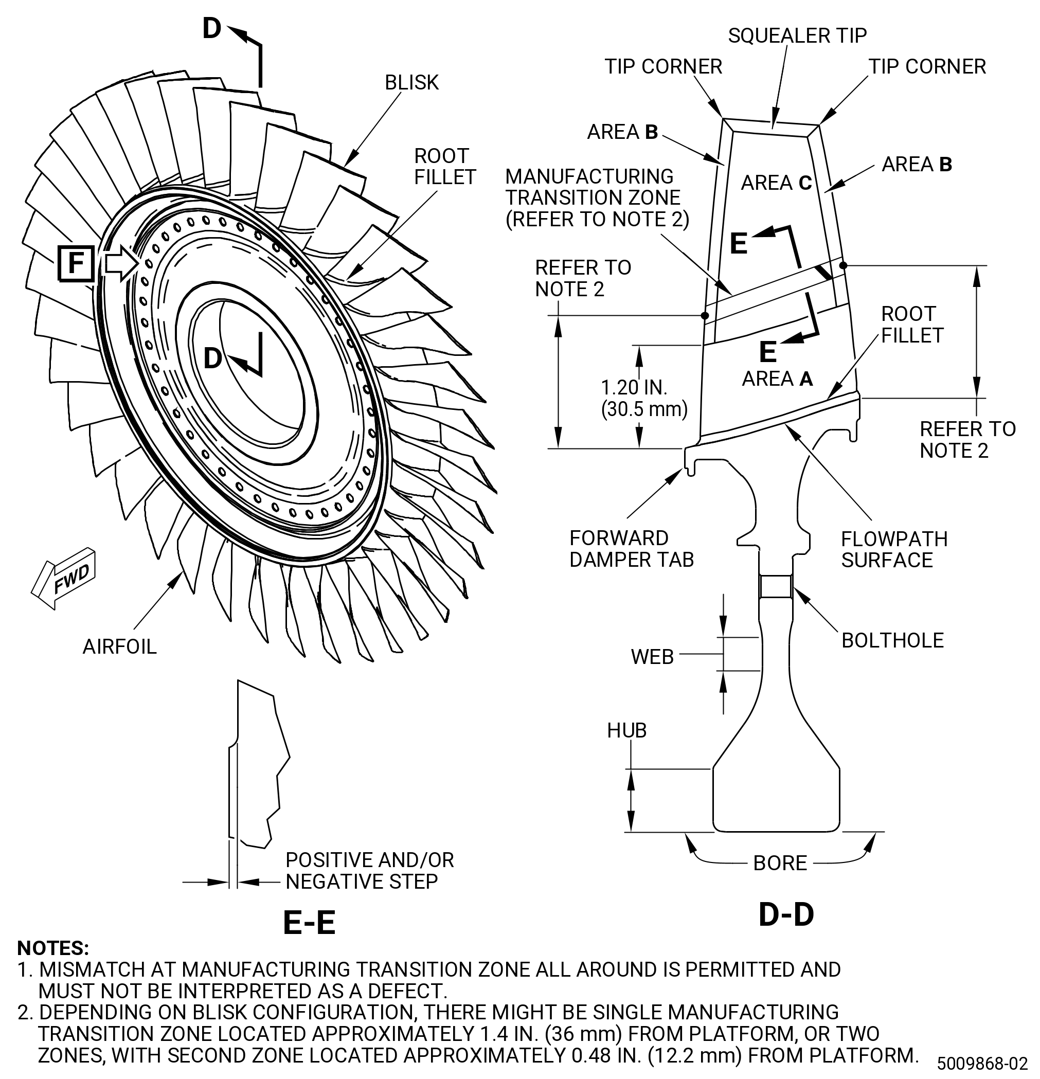
| 5 . | Visual Inspection. |
| Refer to Figure 805. |
| Subtask 72-31-42-220-003 |
| A. | Do an inspection of all areas for: |
| (1) | Cracks: |
| Maximum serviceable limit: |
|
| Repair method: |
|
| Subtask 72-31-42-220-004 |
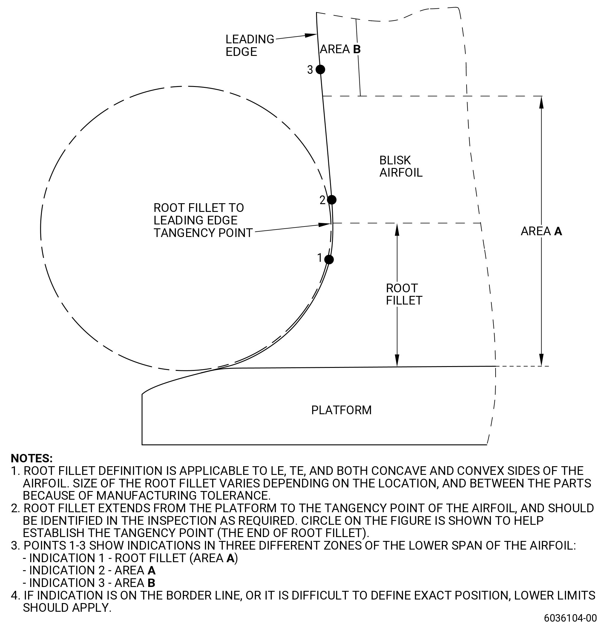
| B. | Do an inspection of area A (critical) for. Refer to Figure 805 and Figure 806. |
| (1) | Nicks, dents, and pits in the fillet: |
| Maximum serviceable limit: |
|
| Repair method: |
|
| Subtask 72-31-42-220-038 |
| (2) | Scratches in the fillet: |
| Maximum serviceable limit: |
|
| Repair method: |
|
| Subtask 72-31-42-220-039 |
| (3) | Tears and cracks in the fillet: |
| Maximum serviceable limit: |
|
| Repair method: |
|
| Subtask 72-31-42-220-040 |
| (4) | Nicks, dents, and pits on the leading and trailing edges: |
| Maximum serviceable limit: |
|
| Repair method: |
|
| Subtask 72-31-42-220-041 |
| (5) | Tears and cracks on the leading and trailing edges: |
| Maximum serviceable limit: |
|
| Repair method: |
|
| Subtask 72-31-42-220-042 |
| (6) | Deposits on the leading and trailing edges: |
| Maximum serviceable limit: |
|
| Repair method: |
|
| Subtask 72-31-42-220-043 |
| (7) | Scratches in area A above the root fillet: |
| Maximum serviceable limit: |
|
| Repair method: |
|
| Subtask 72-31-42-220-044 |
| (8) | Bulge deformation on the leading and trailing edges: |
| Maximum serviceable limit: |
|
| Repair method: |
|
| Subtask 72-31-42-220-005 |
| C. | Do an inspection of area B (leading and trailing edges) on the blisk blade for: |
| (1) | Nicks: |
| Maximum serviceable limit: |
|
| Repair method: |
|
| Subtask 72-31-42-220-006 |
| NOTE: |
|
| (2) | Dents and pits: |
| Maximum serviceable limit: |
|
| Repair method: |
|
| Subtask 72-31-42-220-007 |
| (3) | Scratches and gouges: |
| Maximum serviceable limit: |
|
| Repair method: |
|
| Subtask 72-31-42-220-008 |
| (4) | Deposits: |
| Maximum serviceable limit: |
|
| Repair method: |
|
| Subtask 72-31-42-220-009 |
| (5) | Metal splatter deposits: |
| Maximum serviceable limit: |
|
| Repair method: |
|
| Subtask 72-31-42-220-010 |
| (6) | Erosion on the leading edge: |
| Maximum serviceable limit: |
|
| Repair method: |
|
| Subtask 72-31-42-220-011 |
| (7) | Cracks: |
| Maximum serviceable limit: |
|
| Repair method: |
|
| Subtask 72-31-42-220-012 |
| (8) | Bulge deformation: |
| Maximum serviceable limit: |
|
| Repair method: |
|
| Subtask 72-31-42-220-061 |
| (9) | Tears: |
| Maximum serviceable limit: |
|
| Repair method: |
|
| Subtask 72-31-42-220-013 |
| D. | Do an inspection of area C (concave and convex airfoil contour surfaces) of the blisk blade for: |
| (1) | Nicks, dents, and pits: |
| Maximum serviceable limit: |
|
| Repair method: |
|
| Subtask 72-31-42-220-014 |
| (2) | Scratches: |
| Maximum serviceable limit: |
|
| Repair method: |
|
| Subtask 72-31-42-220-015 |
| (3) | Metal splatter deposits: |
| Maximum serviceable limit: |
|
| Repair method: |
|
| Subtask 72-31-42-220-016 |
| E. | Do an inspection of the airfoil for: |
| (1) | Bent airfoil: |
| Maximum serviceable limit: |
|
| Repair method: |
|
| Subtask 72-31-42-220-017 |
| F. | Do an inspection of the flowpath surface of the blisk for: |
| (1) | Nicks, dents, pits, and scratches: |
| Maximum serviceable limit: |
|
| Repair method: |
|
| Subtask 72-31-42-220-018 |
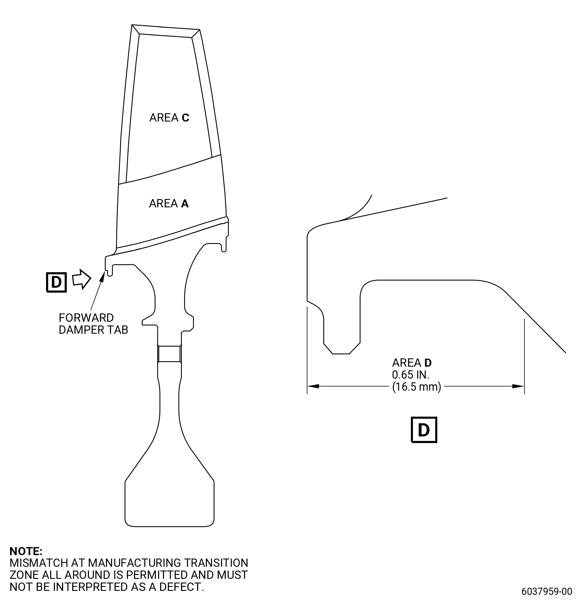
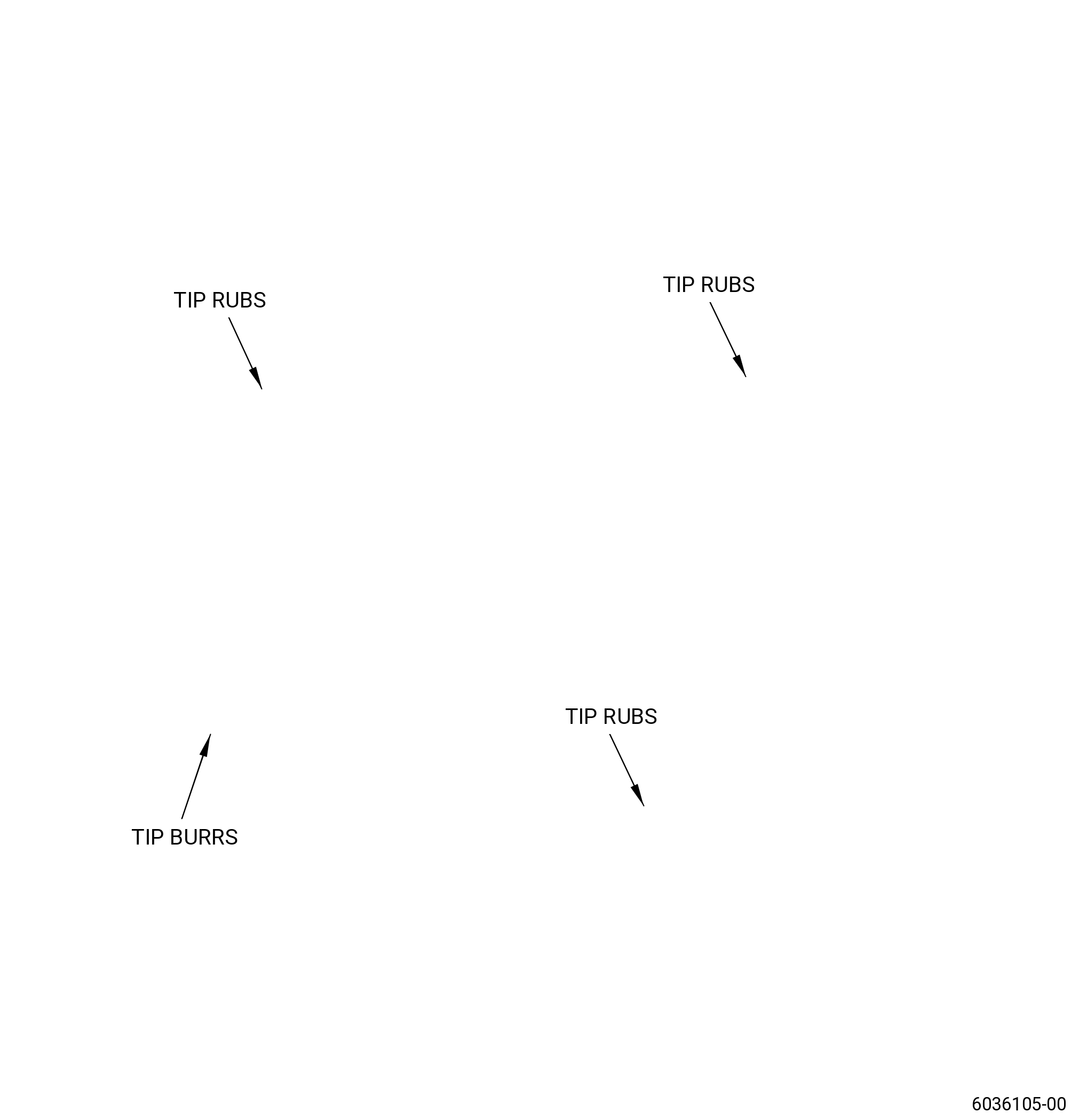
| G. | Do an inspection of the squealer tip of the blisk blade for. Refer to Figure 807. |
| (1) | Cracks: |
| Maximum serviceable limit: |
|
| Repair method: |
|
| Subtask 72-31-42-220-046 |
| (2) | Nicks and dents: |
| Maximum serviceable limit: |
|
| Repair method: |
|
| Subtask 72-31-42-220-019 |
| (3) | Tip rub: |
| NOTE: |
|
| Maximum serviceable limit: |
|
| Repair method: |
|
| Subtask 72-31-42-220-020 |
| (4) | Burrs and high metal: |
| NOTE: |
|
| Maximum serviceable limit: |
|
| Maximum repairable limit: |
|
| Repair method: |
|
| Subtask 72-31-42-220-021 |
| (5) | Heat discoloration caused by tip rub: |
| NOTE: |
|
| NOTE: |
|
| NOTE: |
|
| NOTE: |
|
| Maximum serviceable limit: |
|
| Repair method: |
|
| Subtask 72-31-42-220-022 |
| (6) | Deposits: |
| Maximum serviceable limit: |
|
| Repair method: |
|
| Subtask 72-31-42-220-023 |
| (7) | Bending and curling of the squealer tip: |
| Maximum serviceable limit: |
|
| Repair method: |
|
| Subtask 72-31-42-220-024 |
| (8) | Erosion: |
| Maximum serviceable limit: |
|
| Repair method: |
|
| Subtask 72-31-42-220-026 |
| H. | Do an inspection of the tip corners of the blisk for: |
| (1) | Damage: |
| Maximum serviceable limit: |
|
| Repair method: |
|
| Subtask 72-31-42-220-027 |
| I. | Do an inspection of the boltholes for: |
| (1) | Nicks, dents, and scratches on the inner diameter: |
| Maximum serviceable limit: |
|
| Repair method: |
|
| Subtask 72-31-42-220-028 |
| (2) | Nicks, dents, and scratches on the chamfers: |
| Maximum serviceable limit: |
|
| Repair method: |
|
| Subtask 72-31-42-220-029 |
| (3) | Fretting, galling, or wear: |
| Maximum serviceable limit: |
|
| Repair method: |
|
| Subtask 72-31-42-220-047 |
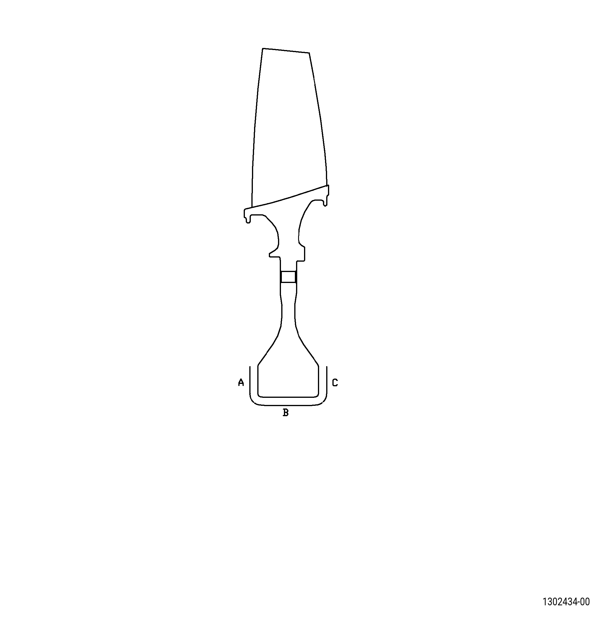
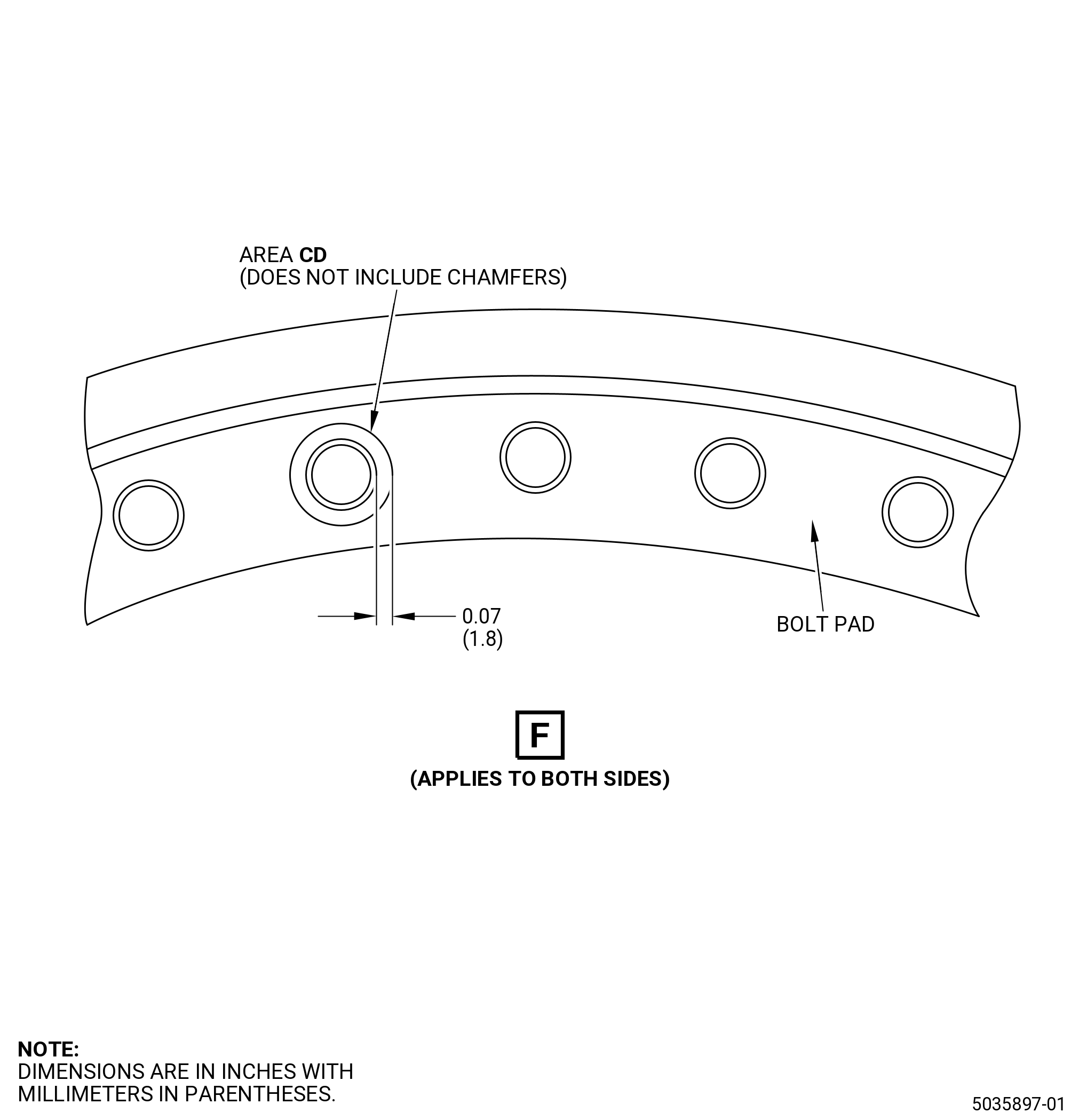
| J. | Do an inspection of the bolt pads for. Refer to Figure 805. |
| (1) | Fretting or galling: |
| Maximum serviceable limit: |
|
| Repair method: |
|
| Subtask 72-31-42-220-048 |
| (2) | Nicks, dents, pits, and scratches: |
| Maximum serviceable limit: |
|
| Repair method: |
|
| Subtask 72-31-42-220-066 |
| (3) | Nicks, dents, pits, and scratches in area CD in 0.070 inch (1.80 mm) of the bolthole chamfers: |
| Maximum serviceable limit: |
|
| Repair method: |
|
| Subtask 72-31-42-220-079 |
| (4) | Fretting in area CD in 0.070 inch (1.80 mm) of the bolthole chamfers (does not include chamfers): |
| Maximum serviceable limit: |
|
| Repair method: |
|
| Subtask 72-31-42-220-049 |
| K. | Do an inspection on forward and aft damper tabs for: |
| (1) | Fretting or galling on aft damper tab: |
| Maximum serviceable limit: |
|
| Repair method: |
|
| Subtask 72-31-42-220-080 |
| (2) | Fretting or galling on forward damper tab (area D). Refer to Figure 805: |
| Maximum serviceable limit: |
|
| Repair method: |
|
| Subtask 72-31-42-220-050 |
| (3) | Nicks, dents, pits, and scratches: |
| Maximum serviceable limit: |
|
| Repair method: |
|
| Subtask 72-31-42-220-030 |
| L. | Do an inspection of the disk bore for: |
| (1) | Nicks, dents, pits, or scratches: |
| Maximum serviceable limit: |
|
| Repair method: |
|
| Subtask 72-31-42-220-067 |
| M. | Do an inspection of the disk webs for: |
| (1) | Nicks, dents, pits, or scratches: |
| Maximum serviceable limit: |
|
| Repair method: |
|
| Subtask 72-31-42-220-068 |
| N. | Do an inspection of the disk forward and aft rabbet for: |
| (1) | Gouges, nicks, dents, pits, and scratches: |
| Maximum serviceable limit: |
|
| Repair method: |
|
| Subtask 72-31-42-220-069 |
| (2) | Nicks, dents, pits, or scratches in the rabbet fillets: |
| Maximum serviceable limit: |
|
| Repair method: |
|
| Subtask 72-31-42-220-070 |
| O. | Deleted. |
| (1) | Deleted. |
| Maximum serviceable limit: |
|
| Repair method: |
|
| Subtask 72-31-42-220-071 |
| (2) | Deleted. |
| Maximum serviceable limit: |
|
| Repair method: |
|
| Subtask 72-31-42-220-072 |
| P. | Do an inspection of the disk forward lower fillet (area XX) for: |
| (1) | Nicks, dents, pits, or scratches: |
| Maximum serviceable limit: |
|
| Repair method: |
|
| Subtask 72-31-42-220-073 |
| Q. | Do an inspection of the disk aft lower fillet (area AH) for: |
| (1) | Nicks, dents, pits, or scratches: |
| Maximum serviceable limit: |
|
| Repair method: |
|
| Subtask 72-31-42-220-074 |
| R. | Do an inspection of all other areas on the disk portion of the part (does not include airfoils or flowpath) for: |
| (1) | Nicks, dents, and scratches: |
| Maximum serviceable limit: |
|
| Repair method: |
|
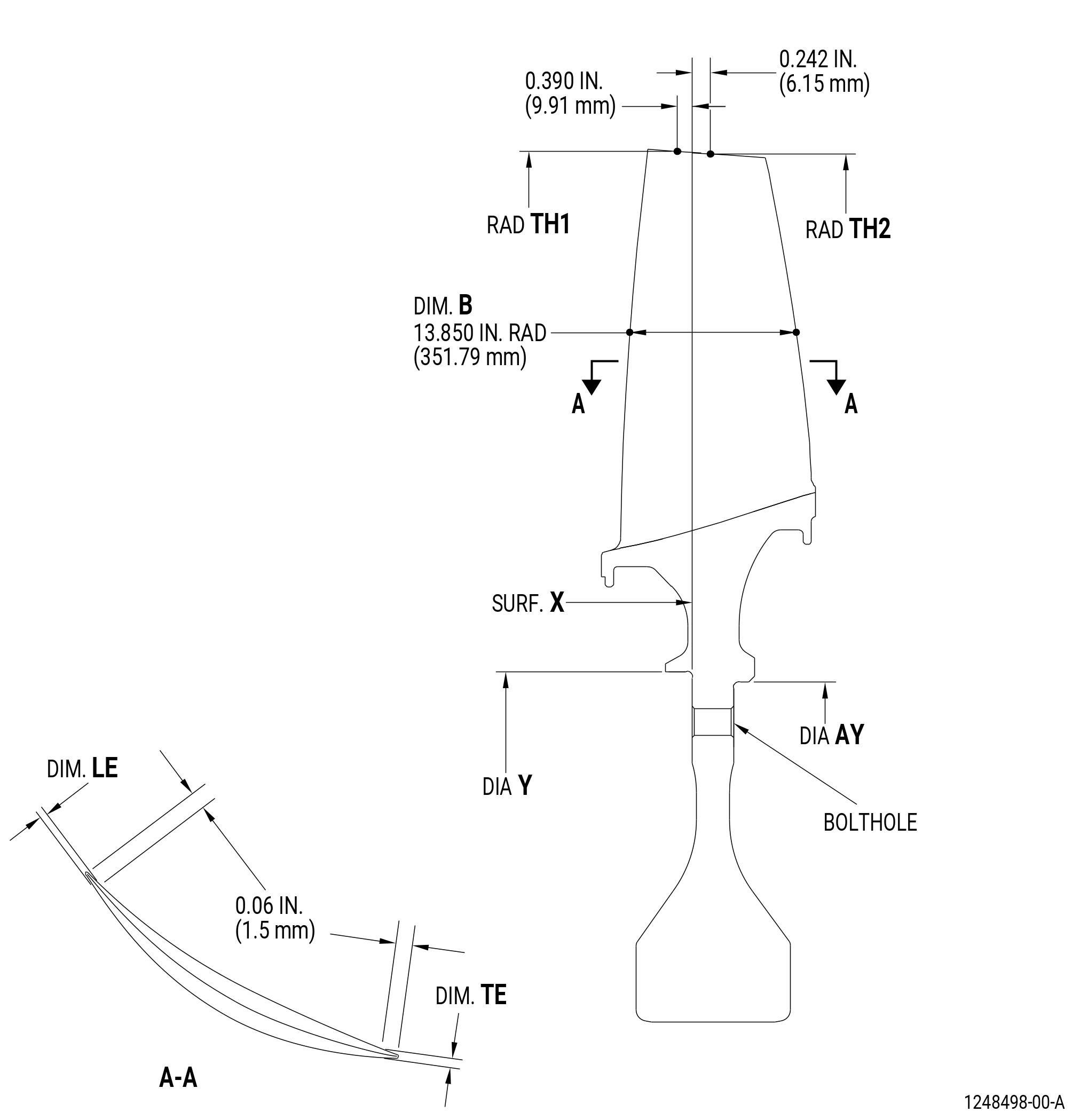
| 6 . | Special Dimensional Inspection. |
| Subtask 72-31-42-220-062 |
| A. | Deleted. |
| Subtask 72-31-42-220-031 |
| B. | Measure all dimensions with diameter Y held within serviceable limits and surface X held flat to 0.001 inch (0.03 mm). |
| Subtask 72-31-42-220-033 |
| C. | Measure the dimensions as follows: |
| (1) | Diameter AY: |
| Minimum serviceable limit: |
|
| Maximum serviceable limit: |
|
| Repair method: |
|
| Subtask 72-31-42-220-035 |
| (2) | Diameter Y: |
| Minimum serviceable limit: |
|
| Maximum serviceable limit: |
|
| Repair method: |
|
| Subtask 72-31-42-220-051 |
| * * * PRE SB 72-0157( HPC Rotor Hardware Release for Non PIP 2 Engines ) |
| (3) | Radius TH1 in relation with surface X and diameter Y: |
| NOTE: |
|
| Minimum serviceable limit: |
|
| Repair method: |
|
| * * * END PRE SB 72-0157 |
| Subtask 72-31-42-220-077 |
| * * * SB 72-0157 |
| (3).A. | Radius TH1 in relation with surface X and diameter Y: |
| NOTE: |
|
| Minimum serviceable limit: |
|
| Repair method: |
|
| * * * END SB 72-0157 |
| Subtask 72-31-42-220-052 |
| * * * PRE SB 72-0157( HPC Rotor Hardware Release for Non PIP 2 Engines ) |
| (4) | Radius TH2 in relation with surface X and diameter Y: |
| NOTE: |
|
| Minimum serviceable limit: |
|
| Repair method: |
|
| * * * END PRE SB 72-0157 |
| Subtask 72-31-42-220-078 |
| * * * SB 72-0157 |
| (4).A. | Radius TH2 in relation with surface X and diameter Y: |
| NOTE: |
|
| Minimum serviceable limit: |
|
| Repair method: |
|
| * * * END SB 72-0157 |
| Subtask 72-31-42-220-053 |
| (5) | Dimension B at radius of 13.850 inch (351.79 mm): |
| NOTE: |
|
| Minimum serviceable limit: |
|
| Repair method: |
|
| Subtask 72-31-42-220-054 |
| * * * PRE SB 72-0157( HPC Rotor Hardware Release for Non PIP 2 Engines ) |
| (6) | Dimension LE of the leading edge thickness: |
| NOTE: |
|
| Minimum serviceable limit: |
|
| Repair method: |
|
| * * * END PRE SB 72-0157 |
| Subtask 72-31-42-220-075 |
| * * * SB 72-0157( HPC Rotor Hardware Release for PIP 2 Engines ) |
| (6).A. | Blisk (02-740 , 72-31-00) (SIN 056A2): |
| NOTE: |
|
| (a) | Dimension LE of the leading edge thickness: |
| Minimum serviceable limit: |
|
| Repair method: |
|
| Subtask 72-31-42-220-076 |
| (6).B. | Blisk (02-740A , 72-31-00) (SIN 056A2): |
| NOTE: |
|
| (a) | Dimension LE of the leading edge thickness: |
| Minimum serviceable limit: |
|
| Repair method: |
|
| * * * END SB 72-0157 |
| Subtask 72-31-42-220-055 |
| (7) | Dimension TE of the leading edge thickness: |
| NOTE: |
|
| Minimum serviceable limit: |
|
| Repair method: |
|