| GENX-1B CLEANING,INSPECTION,AND REPAIR MANUAL | Dated: 04/30/2019 | |
| CIR 72-31-43 , REPAIR 003 | ||
| HIGH PRESSURE COMPRESSOR ROTOR STAGE 3-4 SPOOL - REPAIR - THERMAL SPRAY REPAIR OF THE SEAL TEETH | ||
| GENX-1B CLEANING,INSPECTION,AND REPAIR MANUAL | Dated: 04/30/2019 | |
| CIR 72-31-43 , REPAIR 003 | ||
| HIGH PRESSURE COMPRESSOR ROTOR STAGE 3-4 SPOOL - REPAIR - THERMAL SPRAY REPAIR OF THE SEAL TEETH | ||
| * * * FOR ALL |
| TASK 72-31-43-300-801 |
| 1 . | Repair for the High Pressure Compressor Rotor Stage 3-4 Spool. |
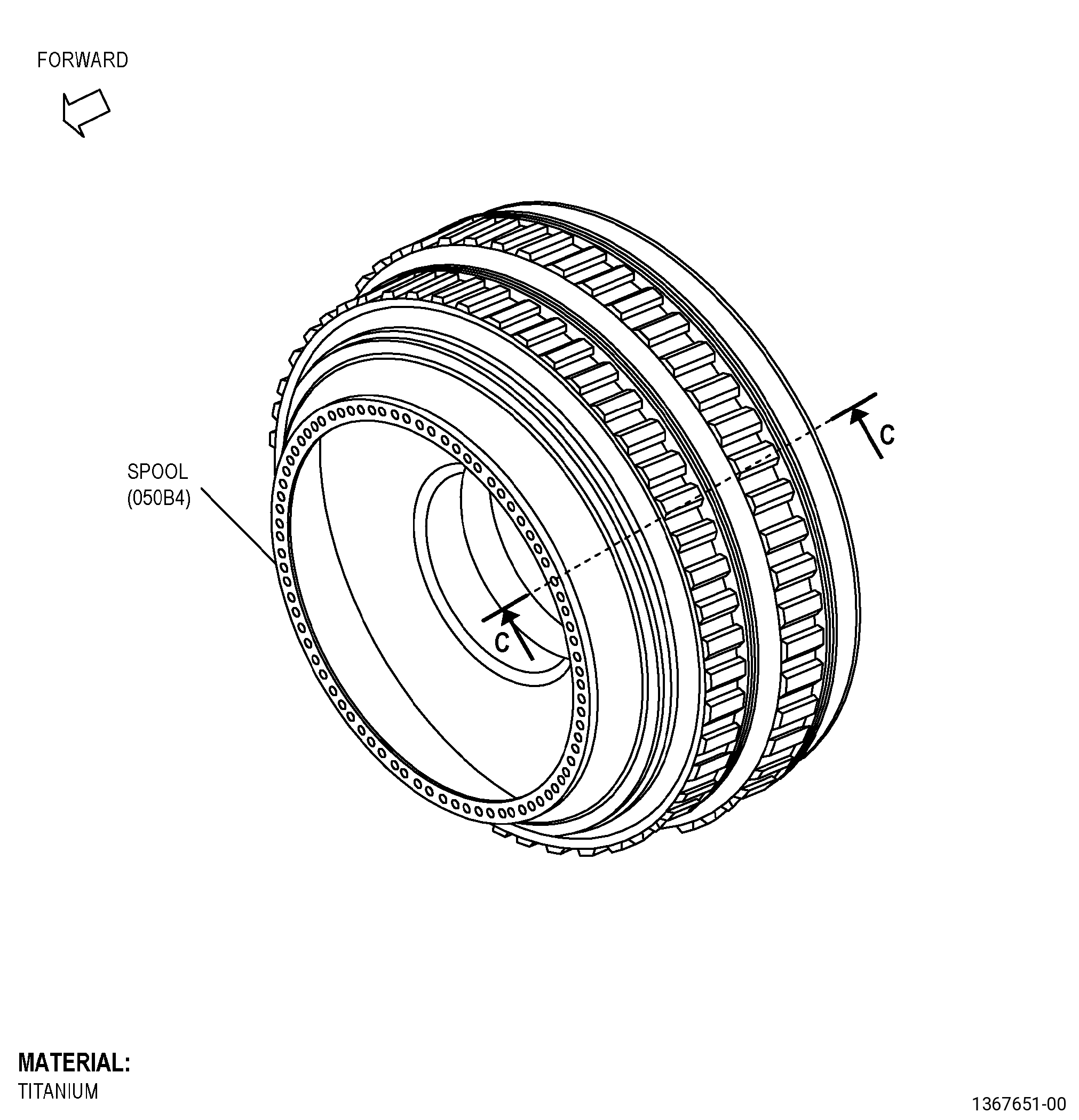
| A. | This procedure gives instructions to repair the high pressure compressor rotor stage 3-4 spool (spool) seal teeth by removing the existing coating and recoating. Refer to Figure 901. |
| B. | The following maximum repairable limits apply to this repair: |
| NOTE: |
|
| (4) | Visual Inspection. |
| (h) | Do an inspection of the seal teeth for: |
| 1 | Chipped or missing coating on lateral faces of diameter SS and diameter TT after recoat: |
| Maximum repairable limit: |
|
| 2 | Missing coating on the seal tip of diameter SS and diameter TT: |
| Maximum repairable limit: |
|
| (6) | Special Dimensional Inspection. |
| (e) | Measure the interstage air seal teeth diameters for: |
| 4 | Diameter SS: |
| Maximum repairable limit: |
|
| 5 | Diameter TT: |
| Maximum repairable limit: |
|
| C. | The subsequent table gives a list of the part numbers that are applicable to this repair. All part numbers are applicable to all paragraphs unless specified differently. |
|
|||||||||||||||||||||||
| D. | Proprietary/Complex Process Statement. |
| (1) | None. |
| 2 . | Tools, Equipment, and Materials. |
| NOTE: |
|
| A. | Tools and Equipment. |
| (1) | Special Tools. None. |
| (2) | Standard Tools and Equipment. None. |
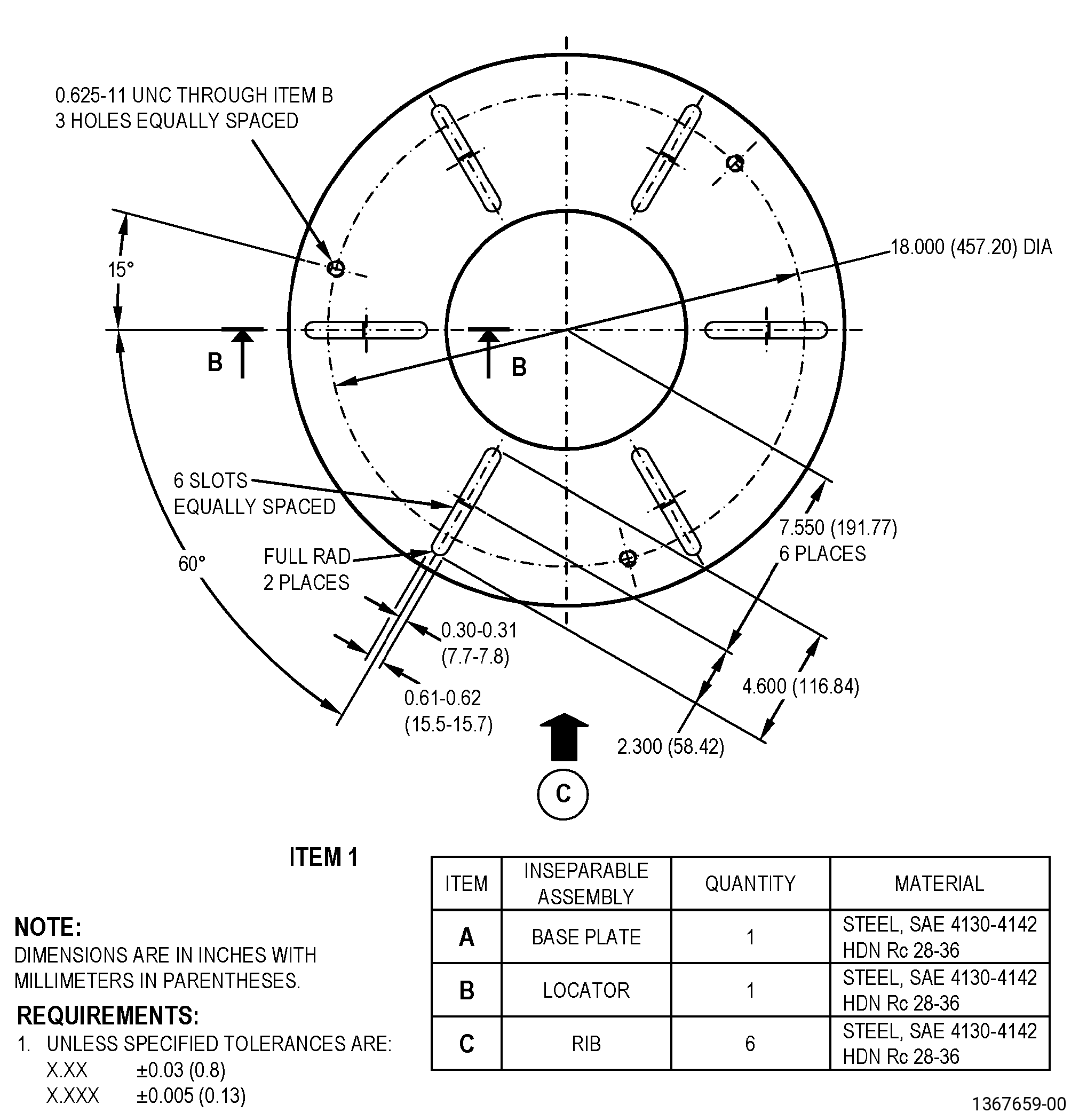
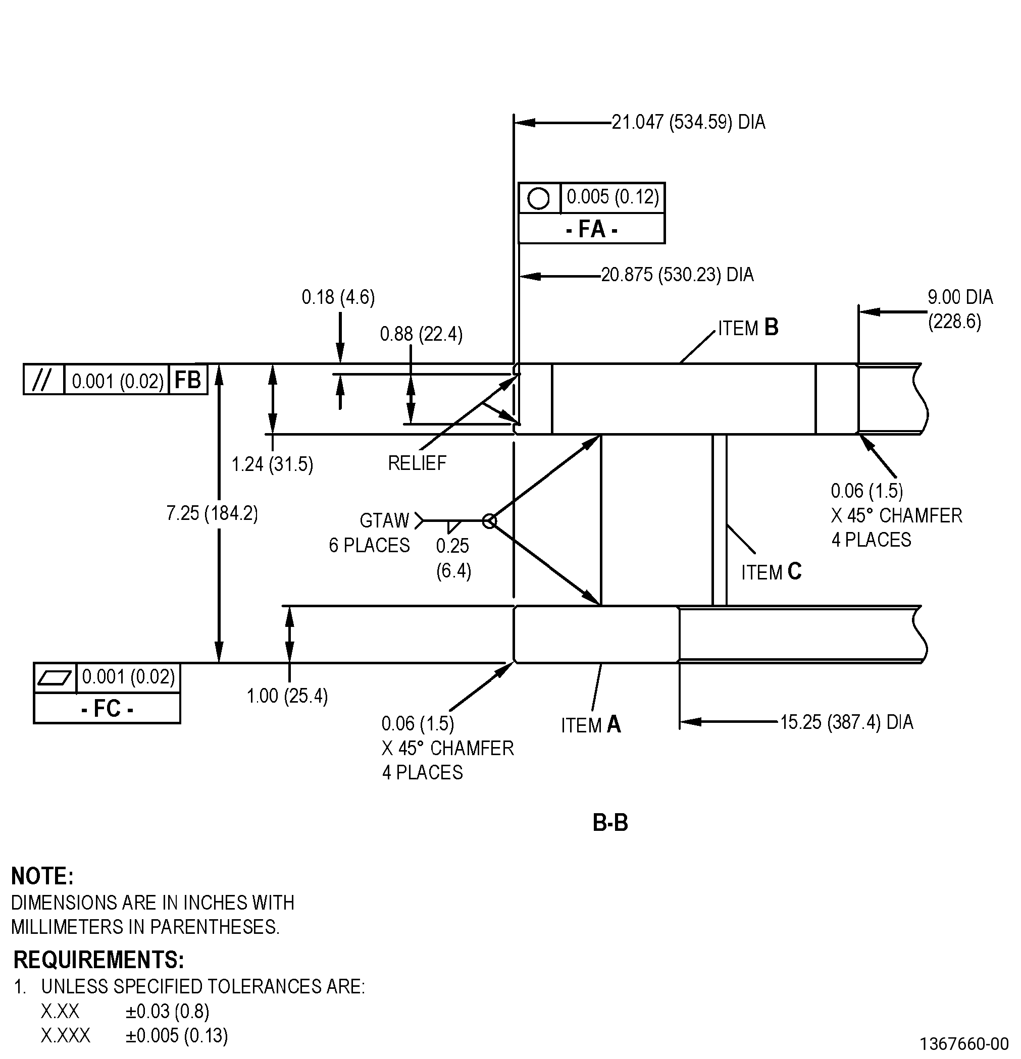
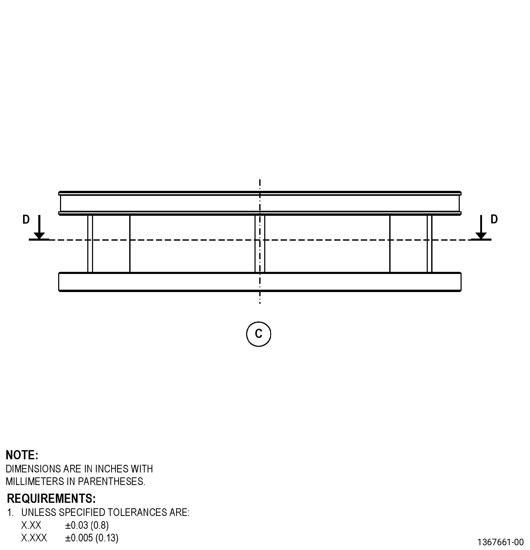
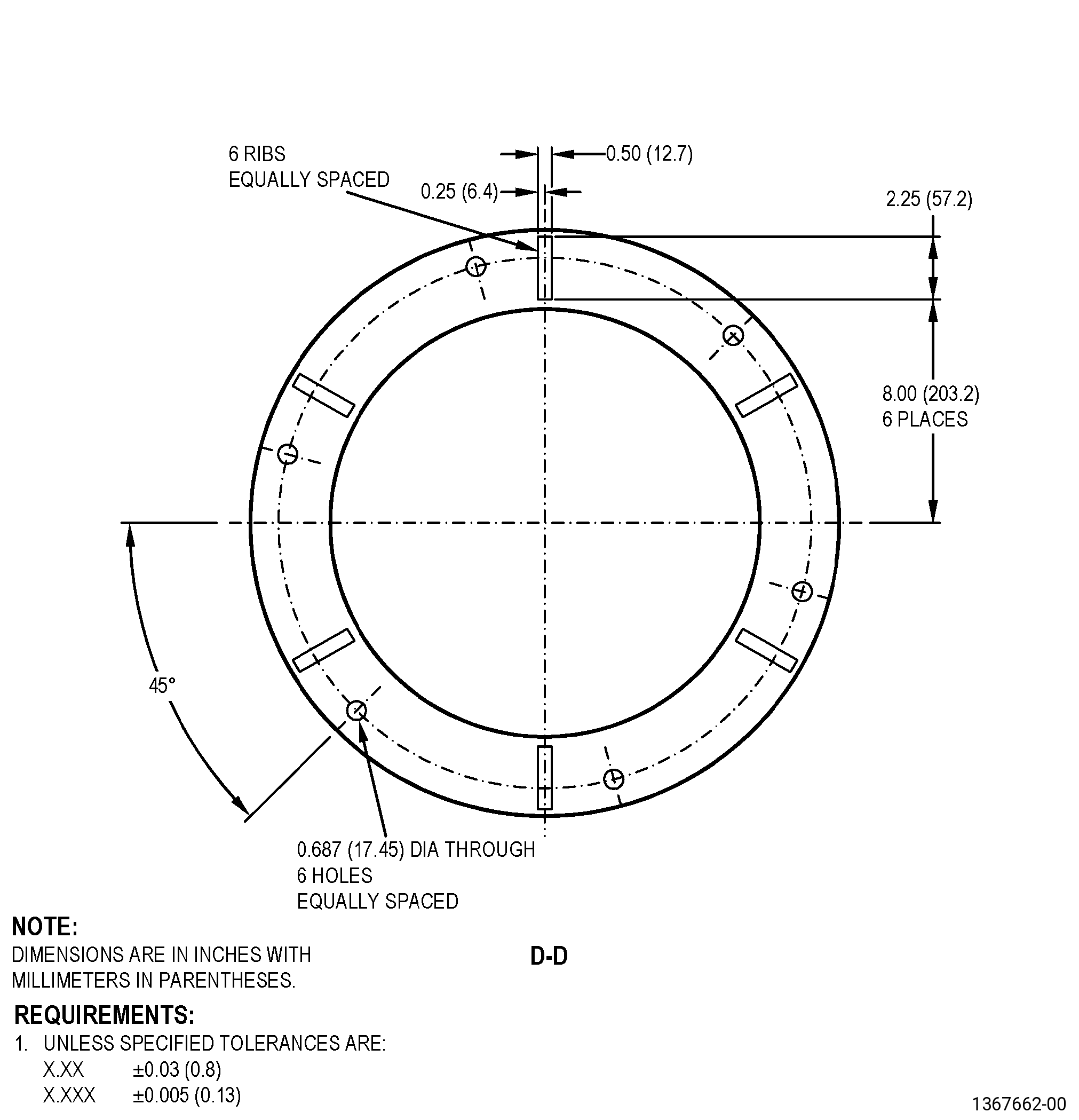
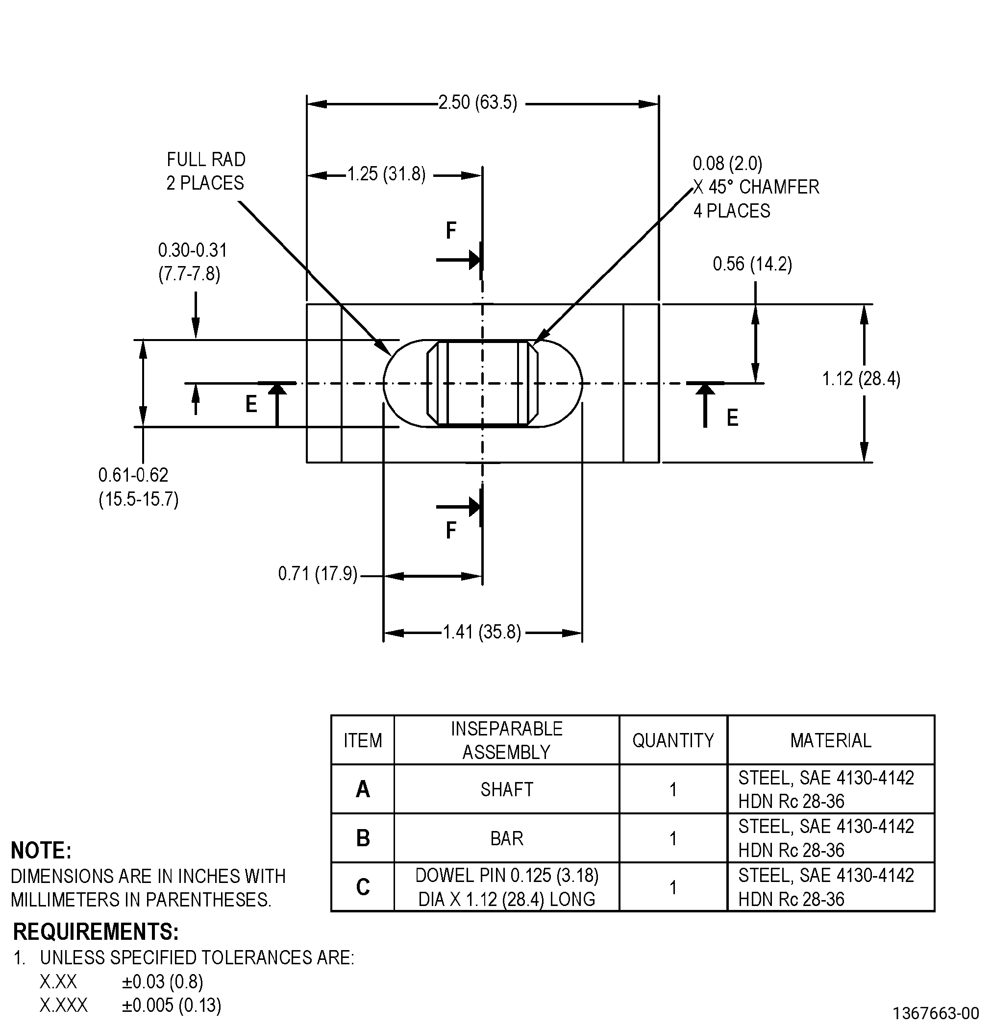
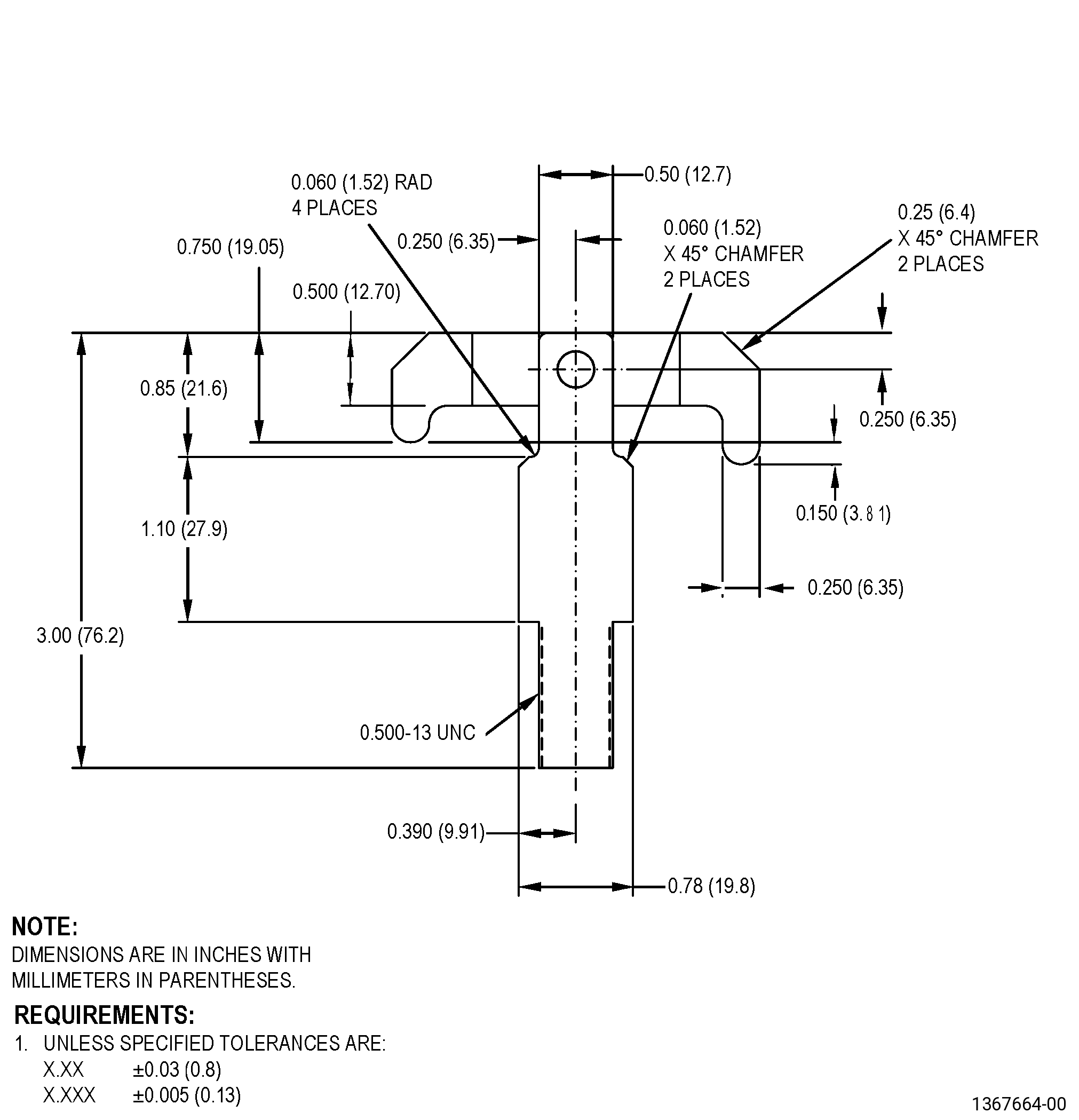
| (3) | Locally Manufactured Tools. |
|
| B. | Consumable Materials. |
| C. | Referenced Procedures. |
|
| D. | Expendable Parts. None. |
| E. | SPD Information. None. |
| (1) | Locally Manufactured SPD. None. |
| F. | Special Solutions. None. |
| G. | Test Specimens. Refer to TASK 70-49-02-340-003 (THERMAL SPRAYING ALUMINUM OXIDE - ALUMINA (POWDER)) and TASK 70-49-10-340-011 (THERMAL SPRAYING NICKEL-ALUMINUM (POWDER)) . |
| 3 . | Dimensional Information. |
| Subtask 72-31-43-220-048 |
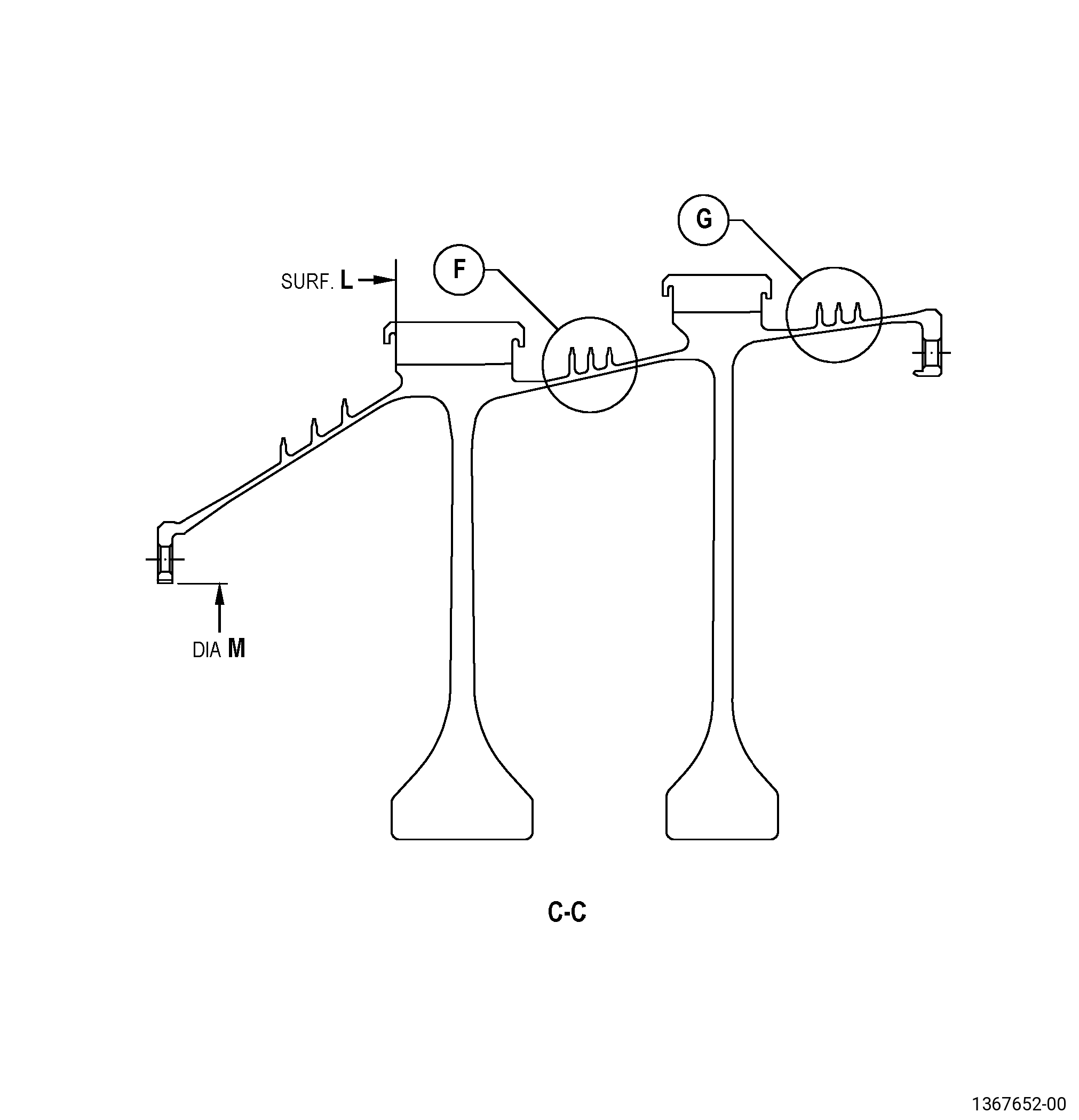
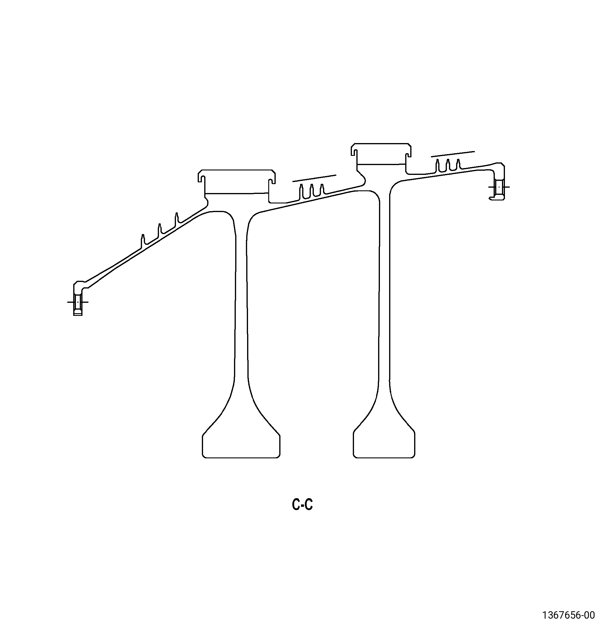
| A. | Refer to Figure 901 and Figure 902 for specified dimensions and locations. |
| NOTE: |
|
|
| 4 . | Setup Information. |
| Subtask 72-31-43-350-003 |
| A. | Set-up the spool for thermal spraying/shotpeening/water jet as follows: |
| Subtask 72-31-43-930-001 |
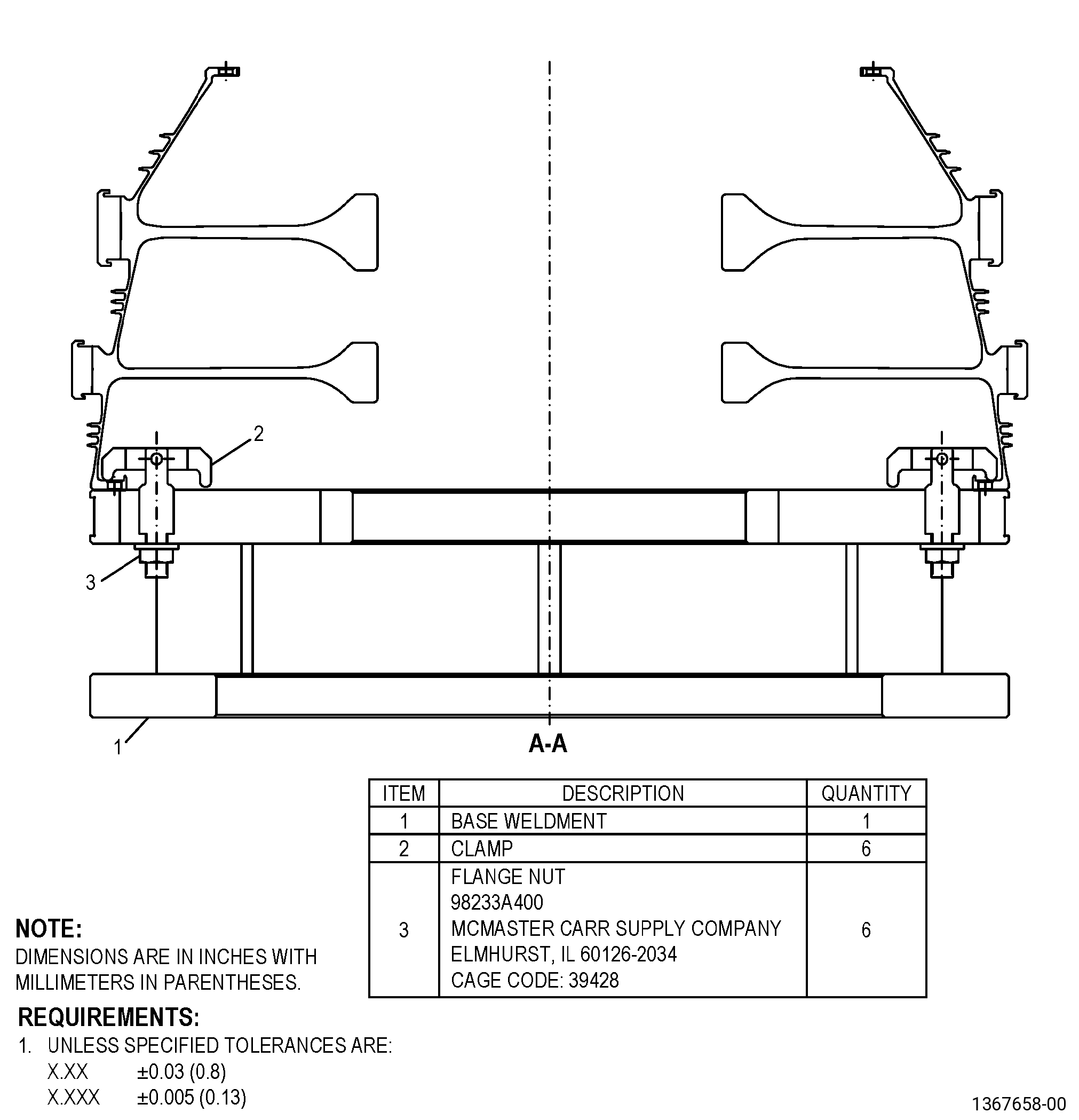
| (1) | If necessary, make a holding fixture. |
| Subtask 72-31-43-350-004 |
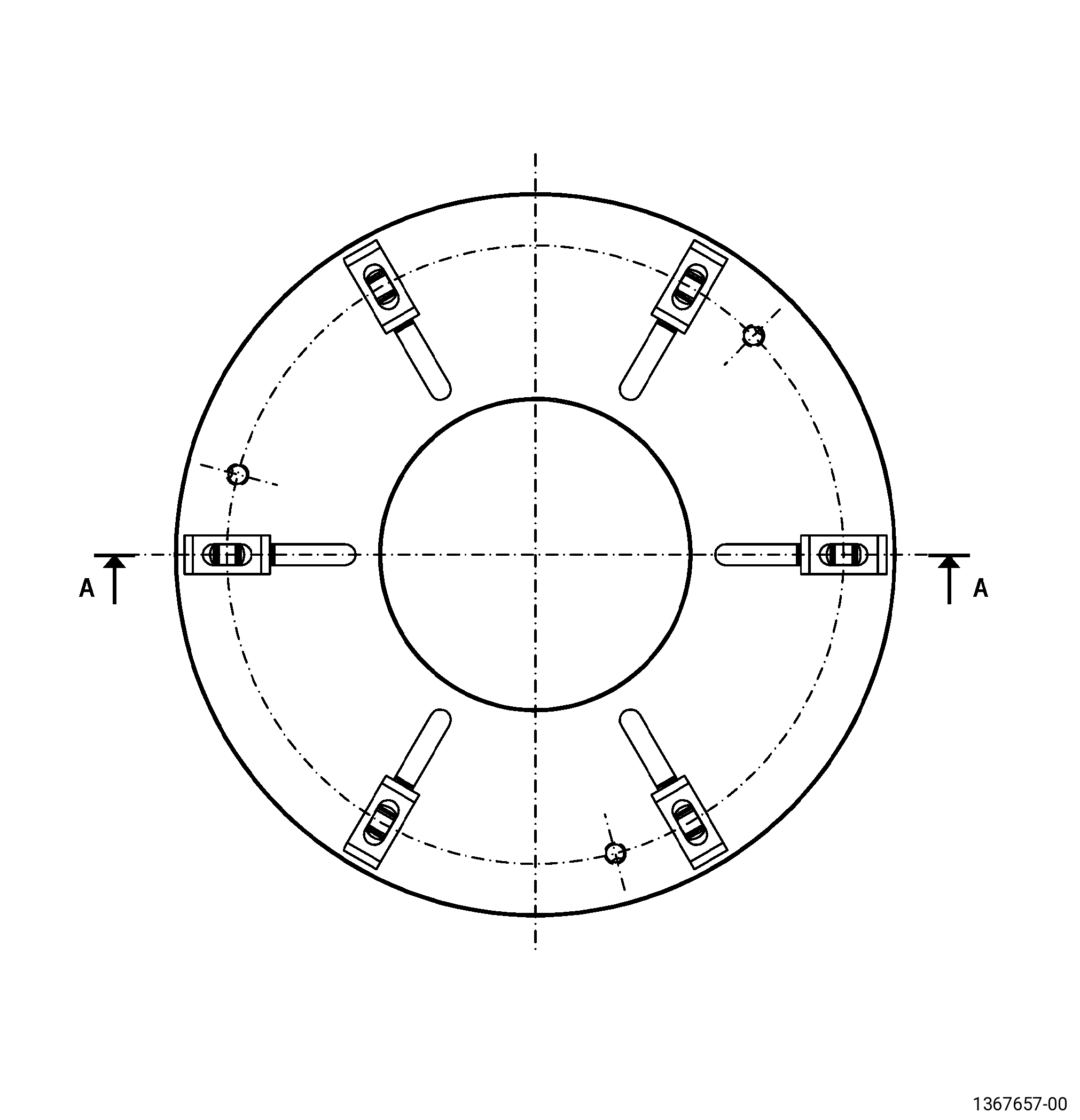
| (2) | Install the spool on a holding fixture or on the machine table. Refer to Figure 902, Figure 904, and as follows: |
| (a) | Surface L must be flat to 0.050 inch (1.27 mm) or less. |
| (b) | Diameter M must have a runout of 0.050 inch (1.27 mm) or less. |
| Subtask 72-31-43-350-005 |
| B. | Set-up the spool for machining as follows: |
| Subtask 72-31-43-930-002 |
| (1) | If necessary, make the machining fixture. Refer to Figure 905. |
| Subtask 72-31-43-350-006 |
| (2) | Install the spool on the fixture aft end down. Refer to Figure 902, Figure 904, and as follows: |
| (a) | Surface L must be flat to 0.002 inch (0.05 mm) or less. |
| (b) | Diameter M must have a runout of 0.002 inch (0.05 mm) or less. |
| 5 . | Procedure. |
| Subtask 72-31-43-100-002 |
| A. | Alternative Procedure Available. Remove the coating from the spool seal teeth as follows: |
| (1) | Set-up the spool for coating removal. Refer to Figure 904, Subtask 72-31-43-350-003 (paragraph 4.A.), Setup Information, and Subtask 72-31-43-350-005 (paragraph 4.B.), Setup Information. |
| (2) | Remove the thermal coating from the spool seal teeth. Refer to TASK 70-23-00-100-001 (STRIPPING PROCEDURES) and TASK 70-23-23-330-008 (REMOVAL OF COATINGS BY HIGH PRESSURE WATER STRIPPING). |
| Subtask 72-31-43-100-003 |
| A.A. | Alternative Procedure. Remove the coatings from the seal teeth as follows: |
| (1) | Remove the top coating and bond coating from the seal teeth. Refer to TASK 70-21-04-120-001 (CLEANING METHOD NO. 4 - DRY ABRASIVE BLAST CLEANING), TASK 70-23-00-100-001 (STRIPPING PROCEDURES), and TASK 70-23-12-110-027 (STRIPPING THERMAL SPRAYED COATINGS) and as follows: |
| (a) | If necessary, grit-blast thermal spray coating to remove top coat. Refer to TASK 70-21-04-120-A01 (DRY ABRASIVE BLAST CLEANING METHOD 4A) and as follows: |
| 1 | Apply C10-012 tape to areas that you will not grit blast. |
| 2 | Use C04-113 aluminum oxide at 75-90 psia (517-621 kPa). |
| (b) | If necessary, apply C10-012 tape again. |
| (c) | Remove the bond coating. Refer to TASK 70-23-00-100-001 (STRIPPING PROCEDURES). |
| (d) | Remove the tape. |
| (e) | If necessary, remove the remaining coating residue with a plastic media blast. Refer to TASK 70-21-04-120-E01 (DRY ABRASIVE BLAST CLEANING METHOD 4E). |
| (f) | If you used plastic media blast, clean to remove the plastic media residue. Refer to TASK 70-21-09-110-007 (CLEANING METHOD NO. 9 - LIGHT-DUTY ALKALINE CLEANING OF TITANIUM ALLOYS). |
| Subtask 72-31-43-220-049 |
| B. | Do a dimensional inspection of the repair diameters. Refer to Subtask 72-31-43-220-048 (paragraph 3.A.), Dimensional Information, and as follows: |
| (1) | Measure each diameter at eight equally-spaced locations and calculate the average diameter dimension. |
| (2) | If the repair diameter is within in-process dimensions and there is no damage on the surface, refer to Subtask 72-31-43-200-002 (paragraph 5.G.). |
| (3) | If the repair diameter is within in-process dimensions but there are damages or remaining coating on the diameter surface or if the diameter is more than the maximum in-process dimension, machine the diameter. Refer to Subtask 72-31-43-320-001 (paragraph 5.C.). |
| (4) | If the repair diameter is less than the minimum in-process dimension, the spool is not repairable with this repair procedure. |
| Subtask 72-31-43-320-001 |
| C. | If necessary, machine the seal tooth tip diameters. Refer to TASK 70-00-03-800-004 (MACHINING DATA), Subtask 72-31-43-220-048 (paragraph 3.A.), Dimensional Information, Figure 902, and as follows: |
| (1) | Set-up the seal for machining. Refer to Subtask 72-31-43-350-003 (paragraph 4.A.), Setup Information, and Subtask 72-31-43-350-005 (paragraph 4.B.), Setup Information. |
| (2) | Machine the seal teeth to the in-process dimensions. |
| Subtask 72-31-43-350-007 |
| D. | If you machined the seal teeth, blend the burrs and rolled edges from the seal teeth. Refer to TASK 70-42-00-350-002 (BLENDING AND REMOVAL OF HIGH METAL PROCEDURES) and as follows: |
| (1) | Break all edges to 0.000-0.004 inch (0.00-0.10 mm). |
| Subtask 72-31-43-100-004 |
| E. | Clean the spool. Refer to TASK 70-21-00-110-051 (CHEMICAL CLEANING) and TASK 70-21-03-160-001 (CLEANING METHOD NO. 3 - STEAM CLEANING). |
| Subtask 72-31-43-110-006 |
| F. | Etch the repair area. Refer to TASK 70-24-00-110-033 (ETCHING PROCEDURES FOR FLUORESCENT-PENETRANT INSPECTION), TASK 70-24-01-110-034 (SWAB ETCHING PROCEDURE), and as follows: |
| (1) | Use Class B etchant. |
| Subtask 72-31-43-200-002 |
| G. | Do an inspection of the repair diameters. Refer to TASK 70-32-00-200-002 (INDIRECT INSPECTION METHODS), TASK 70-32-03-230-002 (SPOT-FLUORESCENT-PENETRANT INSPECTION), and as follows: |
| (1) | Use Class G penetrant. |
| (2) | Indications more than 0.015 inch (0.38 mm) are not permitted. |
| (3) | Linear indications are not permitted. |
| NOTE: |
|
| Subtask 72-31-43-380-001 |
| H. | Peen the repair diameters. Refer to TASK 70-47-01-380-016 (SHOTPEENING), Figure 903, and as follows: |
| (1) | Use C04-271 S110 steel shot. |
| (2) | Intensity must be 0.006-0.012N. |
| (3) | Overspray is permitted. |
| (4) | Intensity verification is necessary in the seal teeth. |
| Subtask 72-31-43-340-001 |
| WARNING: |
|
| I. | Thermal-spray the spool and the test specimens. Refer to TASK 70-49-00-340-001 (THERMAL SPRAYING), Figure 902, and as follows: |
| Subtask 72-31-43-350-008 |
| (1) | Set-up the seal for thermal spraying. Refer to Subtask 72-31-43-350-003 (paragraph 4.A.), Setup Information, and Subtask 72-31-43-350-005 (paragraph 4.B.), Setup Information. |
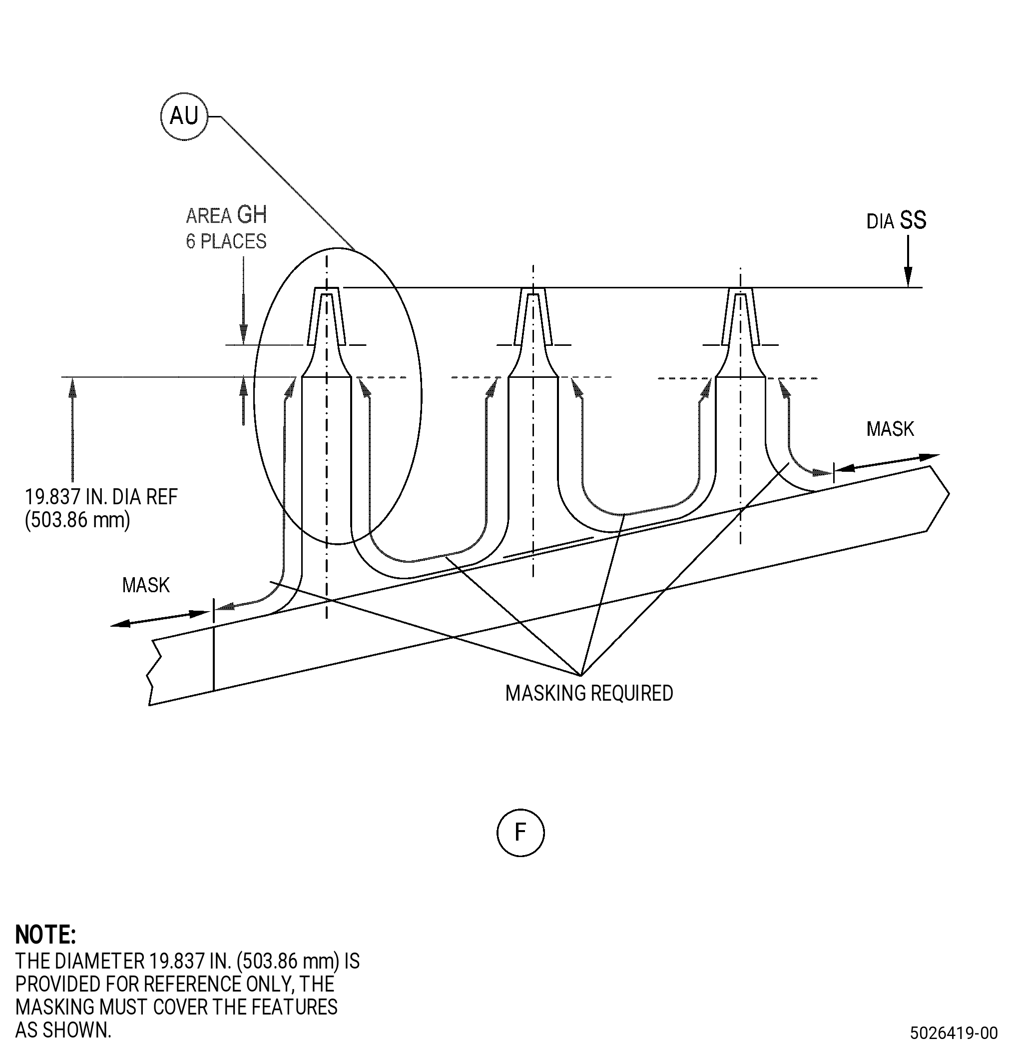
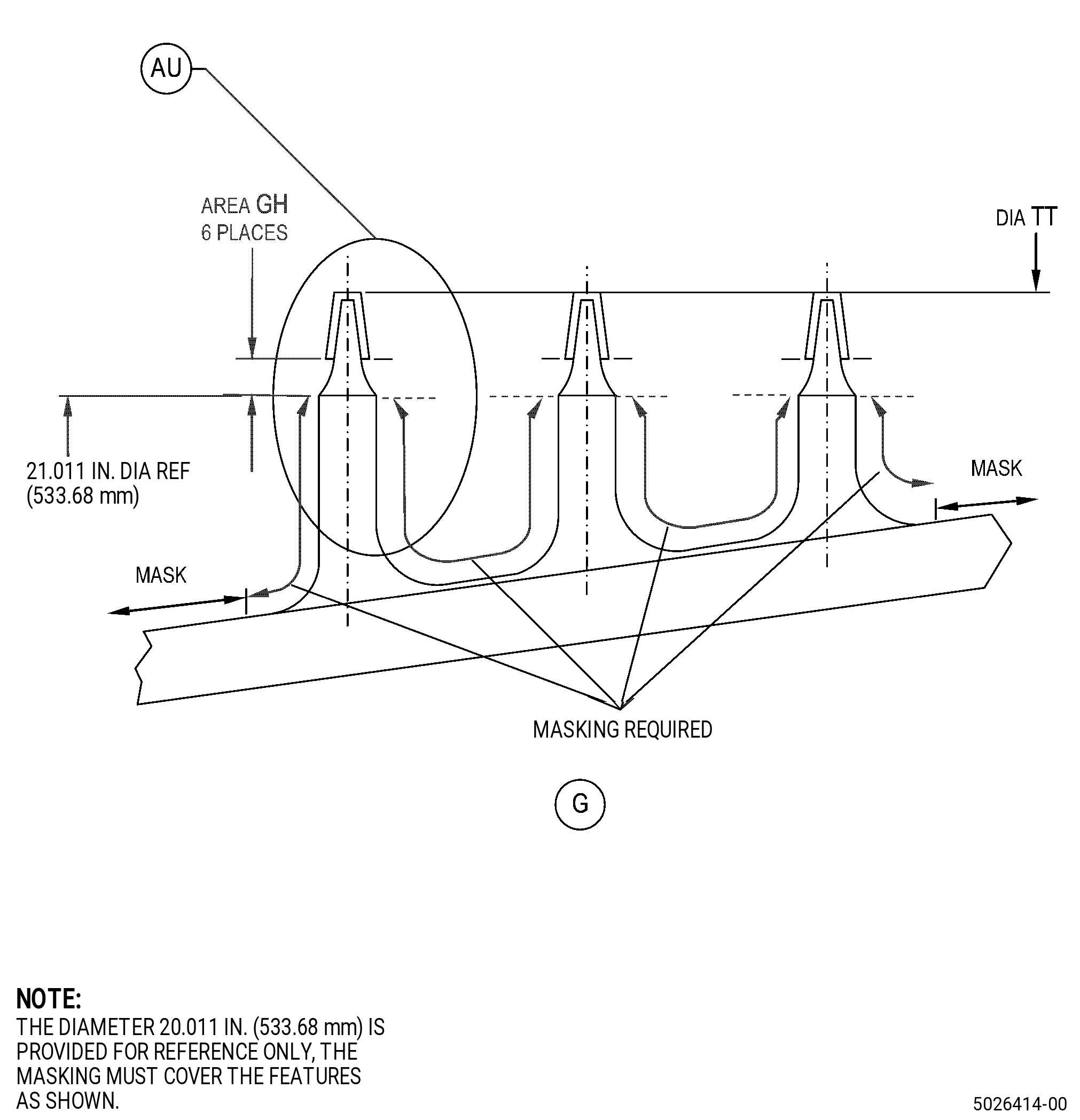
| (2) | Apply a mask to the part. Refer to Figure 902 and as follows: |
| (a) | Use C10-012 tape. |
| Subtask 72-31-43-140-001 |
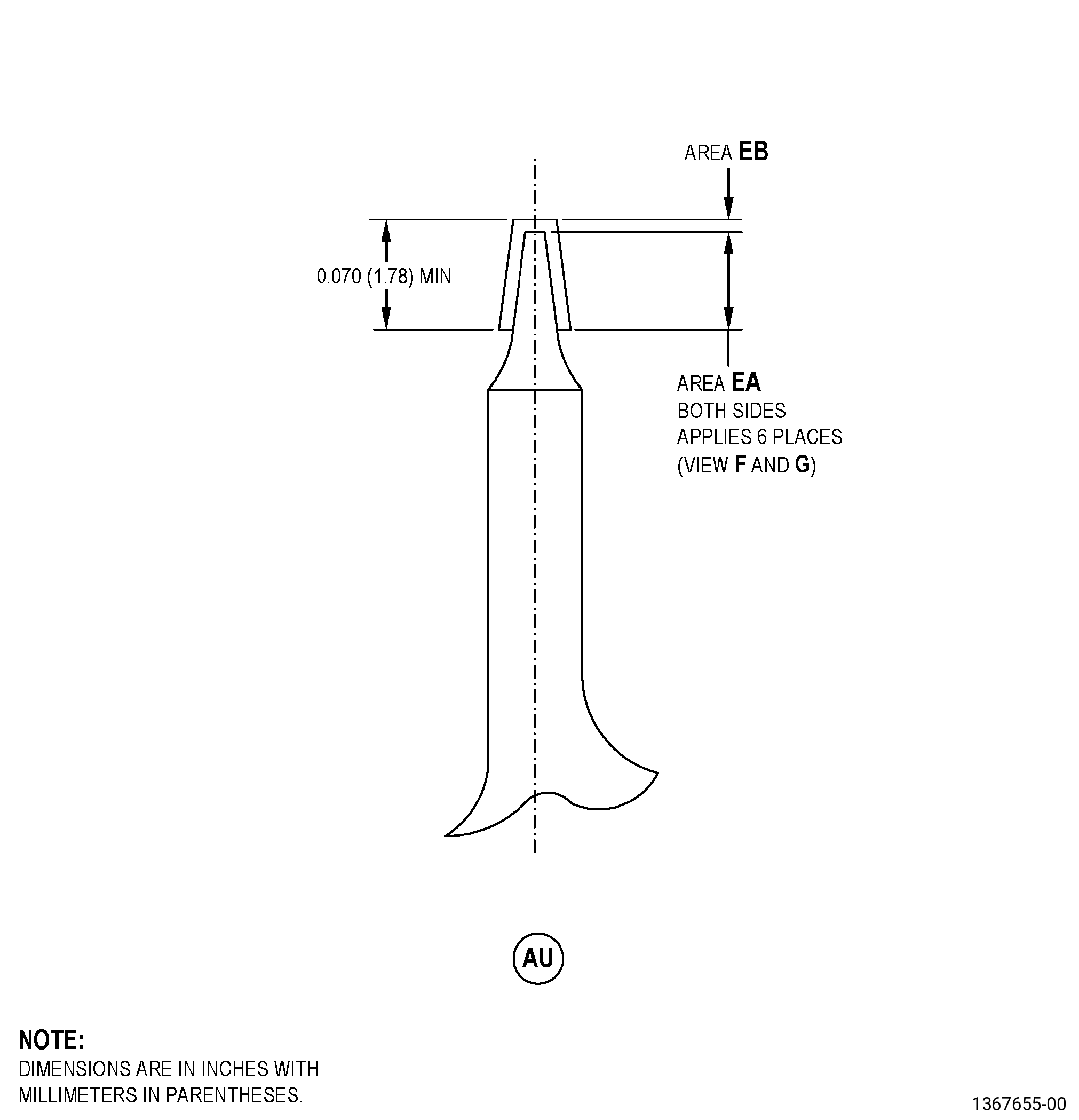
| (3) | Grit blast area EA, area EB and the test specimens. Refer to Figure 902 and as follows: |
| (a) | The final surface finish must agree with titanium-base material. |
| Subtask 72-31-43-100-005 |
| (4) | Clean area EA, area EB and the test specimens. Refer to TASK 70-21-00-110-051 (CHEMICAL CLEANING) and TASK 70-21-01-110-001 (CLEANING METHOD NO. 1 - SOLVENT DEGREASING). |
| Subtask 72-31-43-340-002 |
| (5) | Apply bond coat to areas EA and EB on each seal tooth, and to the test specimens. Refer to TASK 70-49-00-340-001 (THERMAL SPRAYING), TASK 70-49-10-340-011 (THERMAL SPRAYING NICKEL-ALUMINUM (POWDER)), Figure 902, and as follows: |
| NOTE: |
|
| (a) | Apply a mask to the part. Refer to Figure 902 and as follows: |
| 1 | Use C10-012 tape. |
| (b) | Overspray is permitted only in area GH. |
| (c) | The bond coating thickness in area EA must be 0.002-0.005 inch (0.06-0.12 mm). |
| (d) | The bond coating thickness in area EB must be 0.002-0.008 inch (0.06-0.20 mm). |
| (e) | Do all the quality assurance tests specified in TASK 70-49-10-340-011 (THERMAL SPRAYING NICKEL-ALUMINUM (POWDER)). |
| (6) | Apply top coat to areas EA and EB on each seal tooth, and to the test specimens. Refer to TASK 70-49-00-340-001 (THERMAL SPRAYING), TASK 70-49-02-340-003 (THERMAL SPRAYING ALUMINUM OXIDE - ALUMINA (POWDER)), Figure 902, and as follows: |
| (a) | If necessary, apply a mask to the part again. Refer to Figure 902 and as follows: |
| 1 | Use C10-012 tape. |
| (b) | Overspray is permitted only in area GH. |
| (c) | The final machined top coating thickness in area EA must be 0.003-0.013 inch (0.08-0.33 mm). |
| (d) | The final top coating thickness in area EB must be 0.003-0.013 inch (0.08-0.33 mm). |
| (e) | Do all the quality assurance tests specified in TASK 70-49-02-340-003 (THERMAL SPRAYING ALUMINUM OXIDE - ALUMINA (POWDER)). |
| 1 | The porosity for the top coat may be less than or equal to V-4. |
| Subtask 72-31-43-320-002 |
| J. | Machine the spool. Refer to TASK 70-00-03-800-004 (MACHINING DATA), Subtask 72-31-43-220-048 (paragraph 3.A.), Dimensional Information, Figure 902, and as follows: |
| (1) | Set-up the seal for machining. Refer to Subtask 72-31-43-350-003 (paragraph 4.A.), Setup Information, and Subtask 72-31-43-350-005 (paragraph 4.B.), Setup Information. |
| (2) | Machine the repair diameters to the finish dimensions. |
| Subtask 72-31-43-100-006 |
| K. | Clean the spool. Refer to TASK 70-21-00-110-051 (CHEMICAL CLEANING) and TASK 70-21-03-160-001 (CLEANING METHOD NO. 3 - STEAM CLEANING). |
| Subtask 72-31-43-200-003 |
| L. | Do a visual inspection of the machined coating on the seal teeth. Refer to TASK 72-31-43-200-801 (72-31-43, INSPECTION 001). |