| GENX-1B CLEANING,INSPECTION,AND REPAIR MANUAL | Dated: 03/11/2024 | |
| CIR 72-31-47 , REPAIR 001 | ||
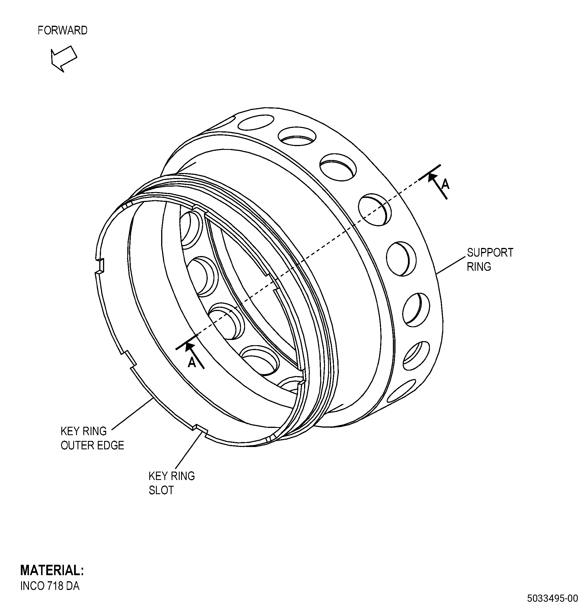
| TUBE SUPPORT RING - REPAIR - THERMAL SPRAY COATING REPLACEMENT | ||
| GENX-1B CLEANING,INSPECTION,AND REPAIR MANUAL | Dated: 03/11/2024 | |
| CIR 72-31-47 , REPAIR 001 | ||
| TUBE SUPPORT RING - REPAIR - THERMAL SPRAY COATING REPLACEMENT | ||
| * * * FOR ALL |
| TASK 72-31-47-300-801 |
| 1 . | Thermal Spray Coating Replacement. |
| A. | This procedure gives instructions to repair the tube support ring by replacing the thermal spray coating on diameter C. Refer to Figure 901. |
| B. | The following maximum repairable limits apply to this repair: |
| NOTE: |
|
| (4) | Visual Inspection. |
| (a) | Do an inspection of the coated area on the ID of the tube support ring for: |
| 1 | Missing coating: |
| Maximum repairable limit: |
|
| 2 | Coating wear: |
| Maximum repairable limit: |
|
| (5) | Special Dimensional Inspection. |
| (b) | Measure the dimensions as follows: |
| 1 | Diameter C: |
| Maximum repairable limit: |
|
| Minimum repairable limit: |
|
| C. | The subsequent table gives a list of the part numbers that are applicable to this repair. All part numbers are applicable to all paragraphs unless specified differently. |
|
|||||||||||||||||||||||
| D. | Proprietary/Complex Process Statement. |
| (1) | None. |
| 2 . | Tools, Equipment, and Materials. |
| NOTE: |
|
| A. | Tools and Equipment. |
| (1) | Special Tools. None. |
| (2) | Standard Tools and Equipment. None. |
| (3) | Locally Manufactured Tools. None. |
| B. | Consumable Materials. |
| C. | Referenced Procedures. |
|
| D. | Expendable Parts. None. |
| E. | SPD Information. |
| (1) | Locally Manufactured SPD. None. |
| F. | Special Solutions. None. |
| G. | Test Specimens. Refer to TASK 70-49-27-340-028 (THERMAL SPRAYING COBALT-MOLYBDENUM-CHROMIUM-SILICON ALLOY (POWDER) - TRIBALOY 400). |
| 3 . | Dimensional Information. |
| Subtask 72-31-47-220-029 |
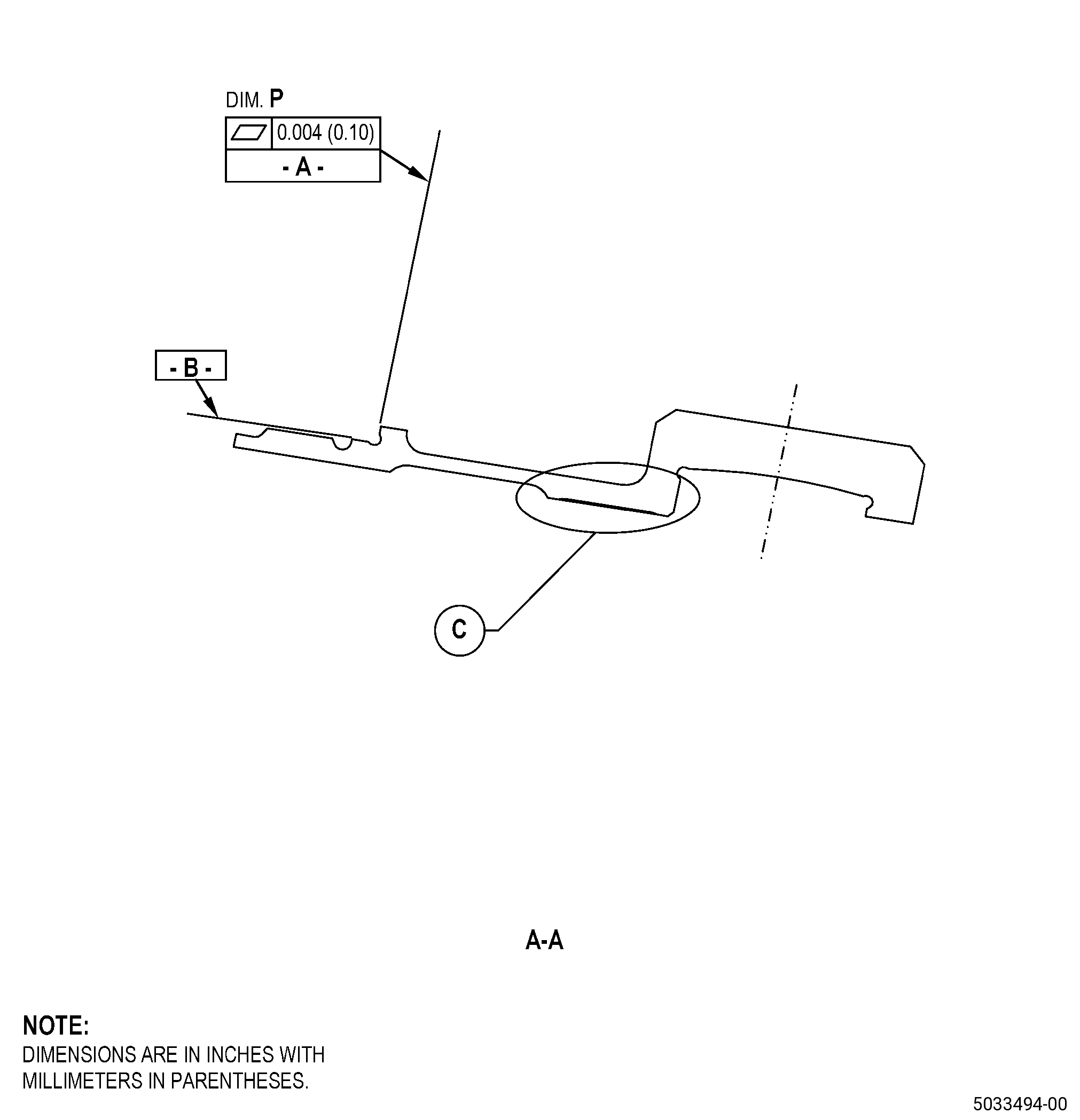
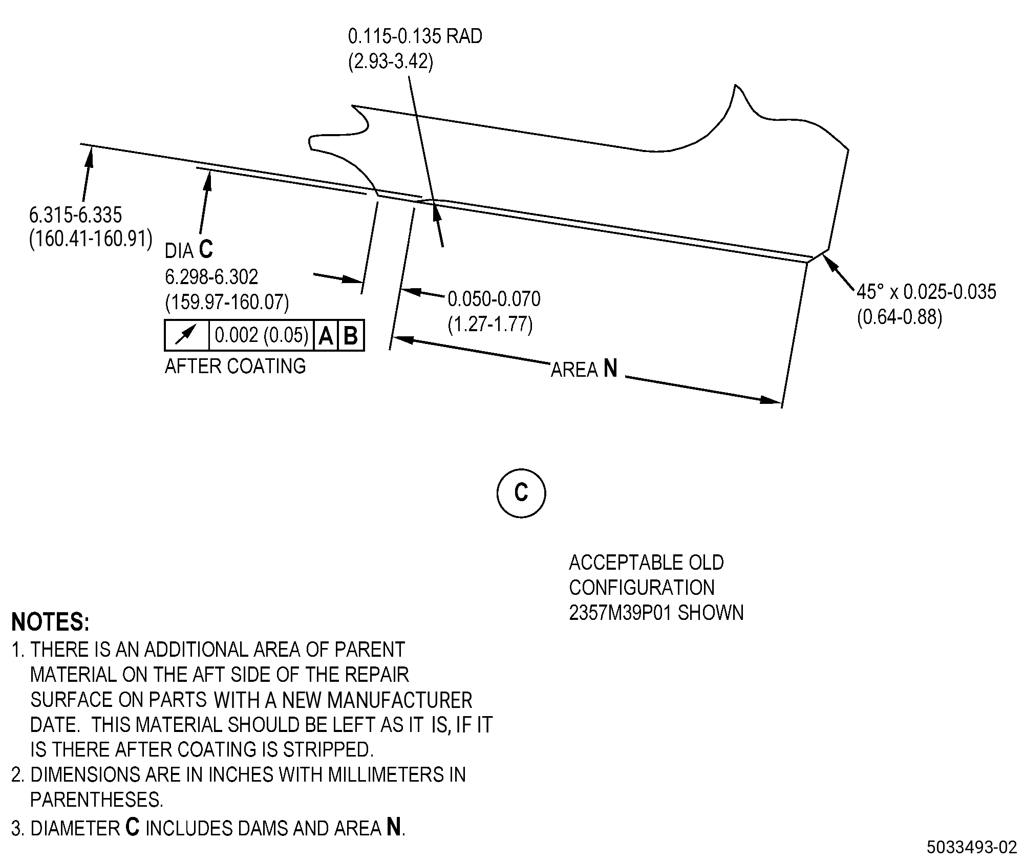
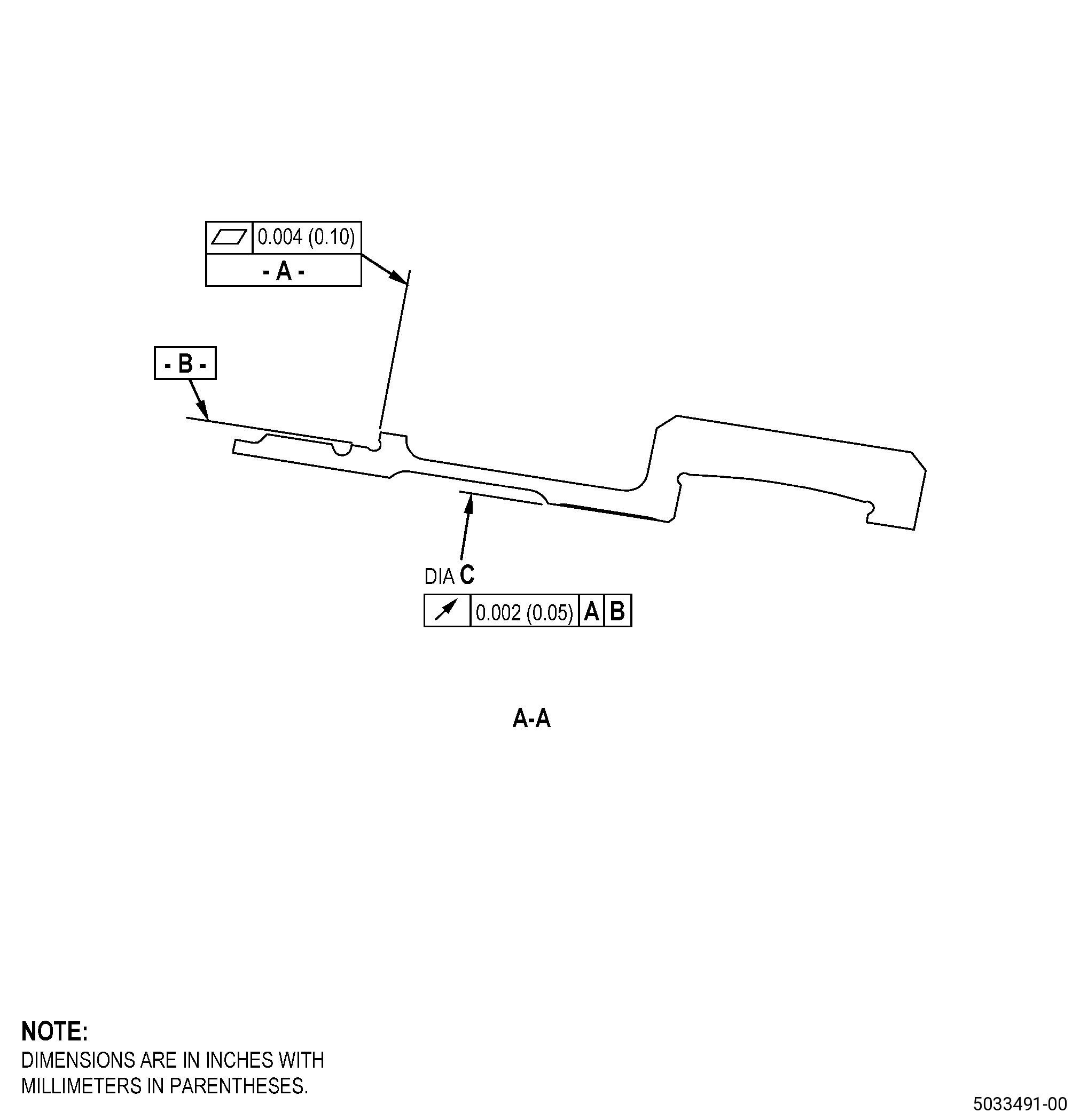
| A. | Refer to Figure 901 for specified dimensions and locations. |
| NOTE: |
|
| NOTE: |
|
|
| 4 . | Setup Information. |
| Subtask 72-31-47-350-001 |
| A. | Set-up the tube support ring for machining. Refer to Figure 902 and as follows: |
| (1) | Set-up the tube support ring to machine the diameter C and as follows: |
| (a) | Install the tube support ring on the machining fixture/machine table as follows: |
| 1 | The runout of Surface A and Diameter B must be 0.002 inch (0.05 mm) or less. |
| 5 . | Procedure. |
| Subtask 72-31-47-110-010 |
| A. | If necessary, clean the tube support ring. Refer to TASK 72-31-47-100-801 (72-31-47, CLEANING 001). |
| Subtask 72-31-47-220-030 |
| B. | Do a visual inspection of the tube support ring. Refer to Figure 901. |
| Subtask 72-31-47-230-002 |
| C. | Do an inspection of the tube support ring. Refer to TASK 70-32-00-200-002 (INDIRECT INSPECTION METHODS), TASK 70-32-03-230-002 (SPOT-FLUORESCENT-PENETRANT INSPECTION), and as follows: |
| (1) | Use Class G penetrant. |
| (2) | If the tube support ring shows fluorescence, it has plasma coating. Go to Subtask 72-31-47-330-001 (paragraph 5.D.). |
| (3) | If the tube support ring does not show fluorescence, it has HVOF coating. Go to Subtask 72-31-47-320-001 (paragraph 5.D.A.). |
| Subtask 72-31-47-330-001 |
| D. | Alternative Procedure Available. Remove the thermal spray coating from the tube support ring diameter C. Refer to TASK 70-23-00-100-001 (STRIPPING PROCEDURES), TASK 70-23-23-330-008 (REMOVAL OF COATINGS BY HIGH PRESSURE WATER STRIPPING), and Figure 901. |
| NOTE: |
|
| Subtask 72-31-47-320-001 |
| CAUTION: |
|
| D.A. | Alternative Procedure. Machine the tube support ring diameter C to remove the thermal spray coating. Refer to TASK 70-00-03-800-004 (MACHINING DATA), Subtask 72-31-47-220-029 (paragraph 3.A.), Figure 901, Figure 902, and as follows: |
| NOTE: |
|
| (1) | Set-up the tube support ring for machining diameter C. Refer to Subtask 72-31-47-350-001 (paragraph 4.A.). |
| (2) | Make sure that you remove the minimum quantity of parent material. |
| Subtask 72-31-47-110-011 |
| E. | If necessary, clean the tube support ring. Refer to TASK 72-31-47-100-801 (72-31-47, CLEANING 001). |
| Subtask 72-31-47-220-031 |
| F. | Do a visual inspection on the tube support ring diameter C for parent metal wear as follows: |
| (1) | Use 10X magnification. |
| (2) | If diameter C has parent wear, measure the depth of wear and machine to in-process dimension diameter C. Do not exceed 6.335 inches (160.91 mm). |
| Subtask 72-31-47-110-012 |
| G. | If you machined the tube support ring to remove the thermal spray coating, etch the diameter C. Refer to TASK 70-24-00-110-033 (ETCHING PROCEDURES FOR FLUORESCENT-PENETRANT INSPECTION), TASK 70-24-01-110-034 (SWAB ETCHING PROCEDURE), and as follows: |
| (1) | Use Class C or Class G etchant. |
| Subtask 72-31-47-230-003 |
| H. | Do an inspection of the tube support ring diameter C. Refer to TASK 70-32-00-200-002 (INDIRECT INSPECTION METHODS), TASK 70-32-03-230-002 (SPOT-FLUORESCENT-PENETRANT INSPECTION), and as follows: |
| (1) | Use Class G penetrant. |
| (2) | Indications that are 0.015 inch (0.38 mm) or less are permitted. |
| Subtask 72-31-47-110-013 |
| I. | Clean the tube support ring diameter C as follows: |
| WARNING: |
|
| (1) | Clean the diameter C with a C10-182 cleaning cloth moist with C04-035 isopropyl alcohol and do as follows: |
| (a) | Replace the dirty cloths with a C10-182 cleaning cloth until the last moist cloth stays clean. |
| Subtask 72-31-47-380-001 |
| J. | Peen the tube support ring diameter C. Refer to TASK 70-47-01-380-016 (SHOTPEENING), Figure 903, and as follows: |
| (1) | Apply C10-021 plastic tape to the tube support ring areas that you will not peen. |
| (2) | Use C04-271 S110 cast steel shot. |
| (3) | Peen the diameter C to an intensity of 9-18N and as follows: |
| (a) | Make sure that you do the intensity verification in a simulative fixture. |
| (4) | Use C10-205 Almen test strips and an almen strip holder to measure the intensity at diameter C. |
| (5) | A minimum of 125 percent coverage is necessary. |
| (6) | Remove the plastic tape from the tube support ring. |
| WARNING: |
|
| (7) | Use a clean, dry shop air to remove the remaining dust and particles from the tube support ring. |
| Subtask 72-31-47-340-001 |
| WARNING: |
|
| K. | Alternative Procedure Available. Thermal-spray the tube support ring diameter C and the test specimens. Refer to TASK 70-49-00-340-001 (THERMAL SPRAYING), TASK 70-49-27-340-028 (THERMAL SPRAYING COBALT-MOLYBDENUM-CHROMIUM-SILICON ALLOY (POWDER) - TRIBALOY 400), Figure 901, Figure 903, and as follows: |
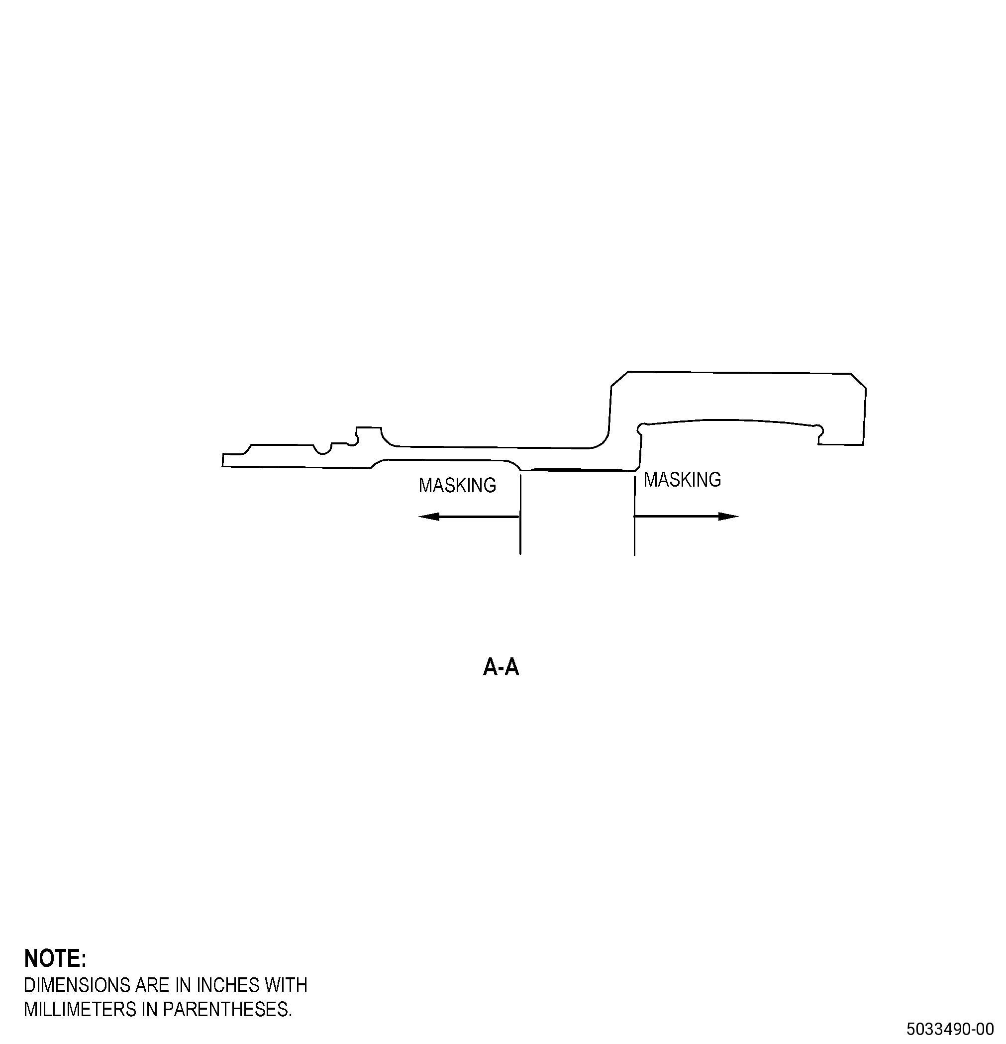
| (1) | Apply C10-012 masking tape to the areas adjacent to area N. |
| (2) | Do the preliminary procedures specified in TASK 70-49-00-340-001 (THERMAL SPRAYING) and as follows: |
| (a) | Use the surface roughness limits for the nickel base material. |
| (3) | Overspray is permitted on dams while you remove it with a machining procedure. |
| (4) | Apply the thermal spray coating as follows: |
| (a) | Make sure that you apply thermal spray coating to the test specimens at the same time, same distance, same angle, and to the same thickness as the tube support ring, and as follows: |
| 1 | Thermal spray coating thickness must be 0.0065-0.0025 inch (0.166-0.63 mm). Make sure that you apply the thermal spray coating with sufficient thickness to get a thickness of 0.0065 inch (0.166 mm) after final machining. Do not exceed than 0.025 inches (0.63 mm) maximum as-sprayed total thickness of coating. |
| (5) | Do all quality assurance testing specified in TASK 70-49-27-340-028 (THERMAL SPRAYING COBALT-MOLYBDENUM-CHROMIUM-SILICON ALLOY (POWDER) - TRIBALOY 400). |
| (6) | Four areas of missing coating are permitted on area N and as follows: |
| (a) | Missing coating can be a maximum size of 0.03 inch (0.7 mm) in diameter and the maximum depth must not be more than the coating thickness. |
| (b) | The minimum distance of each area of missing coating must be 0.50 inch (12.7 mm) from an adjacent area of missing coating. |
| (c) | Each missing coating area must have a smooth and rounded transition at the bottom with no signs of cracking, flaking, chipping, or blistering when you do an inspection at 30X or higher magnification. |
| (7) | Remove the masking tape from the areas adjacent to the diameter C. |
| Subtask 72-31-47-340-002 |
| K.A. | Alternative Procedure. Thermal-spray the tube support ring diameter C and test specimens. Refer to TASK 70-49-00-340-001 (THERMAL SPRAYING), TASK 70-49-48-340-047 (HIGH DENSITY HVOF T-400 (TRIBALOY) COATING), Figure 903, and as follows: |
| (1) | Apply C10-012 masking tape to the areas adjacent to area N. |
| (2) | Do the preliminary procedures specified in TASK 70-49-00-340-001 (THERMAL SPRAYING) and as follows: |
| (a) | Use the surface roughness limits for the nickel base material. |
| (3) | Overspray is permitted on dams while you remove it with a machining procedure. |
| (4) | Apply the thermal spray coating as follows: |
| (a) | Make sure that you apply thermal spray coating to the test specimens at the same time, same distance, same angle, and to the same thickness as the tube support ring, and as follows: |
| 1 | Thermal spray coating thickness must be 0.0065-0.025 inch (0.166-0.63 mm). Make sure that you apply the thermal spray coating with sufficient thickness to get a thickness of 0.0065 inch (0.166 mm) after final machining. Do not exceed than 0.025 inches (0.63 mm) maximum as-sprayed total thickness of coating. |
| (5) | Do all quality assurance testing specified in TASK 70-49-48-340-047 (HIGH DENSITY HVOF T-400 (TRIBALOY) COATING). |
| (6) | Four areas of missing coating are permitted on area N and as follows: |
| (a) | Missing coating can be a maximum size of 0.03 inch (0.76 mm) in diameter and the maximum depth must not be more than the coating thickness. |
| (b) | The minimum distance of each area of missing coating must be 0.50 inch (12.7 mm) from an adjacent area of missing coating. |
| (c) | Each missing coating area must have a smooth and rounded transition at the bottom with no signs of cracking, flaking, chipping, or blistering when you do an inspection at 30X or higher magnification. |
| (7) | Remove the masking tape from the areas adjacent to the diameter C. |
| Subtask 72-31-47-320-002 |
| L. | Machine the tube support ring diameter C. Refer to TASK 70-00-03-800-004 (MACHINING DATA), Subtask 72-31-47-220-029 (paragraph 3.A.), Figure 901, Figure 902, and as follows: |
| (1) | Set-up the tube support ring for machining diameter C. Refer to Subtask 72-31-47-350-001 (paragraph 4.A.). |
| (2) | Machine the diameter C to the finish dimension. |
| (3) | The surface finish must be 32 microinches (0.81 micrometers) or better. |
| (4) | If necessary, blend the diameter C. Refer to TASK 70-42-00-350-002 (BLENDING AND REMOVAL OF HIGH METAL PROCEDURES) and as follows: |
| (a) | Blend the diameter C to remove all high metal or rolled edges. |
| (b) | Break all edges to 0.005-0.015 inch (0.13-0.38 mm). |
| (5) | Remove the tube support ring from the machining fixture/machine table. |
| (6) | Steps are not permitted between area N and the dams. |
| Subtask 72-31-47-220-033 |
| M. | Do a visual inspection of the thermal spray coating on the tube support ring diameter C as follows: |
| (1) | Chipping, flaking, and spalling are not permitted. |
| (2) | The thermal spray coating must have a full, constant coverage in the thermal spray coating areas. |
| (3) | After grinding, do a visual inspection of dam(s), aft face, and chamfer for overspray. Overspray is not permitted on these surfaces. |
| (4) | If diameter C is less than the minimum serviceable limit, do Subtask 72-31-47-230-002 (paragraph 5.C.) thru Subtask 72-31-47-340-001 (paragraph 5.K.) again. |
| Subtask 72-31-47-110-014 |
| WARNING: |
|
| CAUTION: |
|
| N. | Clean the tube support ring. Refer to TASK 70-21-00-110-051 (CHEMICAL CLEANING) and TASK 70-21-03-160-001 (CLEANING METHOD NO. 3 - STEAM CLEANING). |