| GENX-1B CLEANING,INSPECTION,AND REPAIR MANUAL | Dated: 04/30/2019 | |
| CIR 72-53-40 , REPAIR 005 | ||
| HIGH PRESSURE TURBINE ROTOR STAGE 1 DISK - REPAIR - INNER BAYONET TAB REPAIR | ||
| GENX-1B CLEANING,INSPECTION,AND REPAIR MANUAL | Dated: 04/30/2019 | |
| CIR 72-53-40 , REPAIR 005 | ||
| HIGH PRESSURE TURBINE ROTOR STAGE 1 DISK - REPAIR - INNER BAYONET TAB REPAIR | ||
| * * * FOR ALL |
| TASK 72-53-40-300-804 |
| 1 . | Inner Bayonet Tab Repair. |
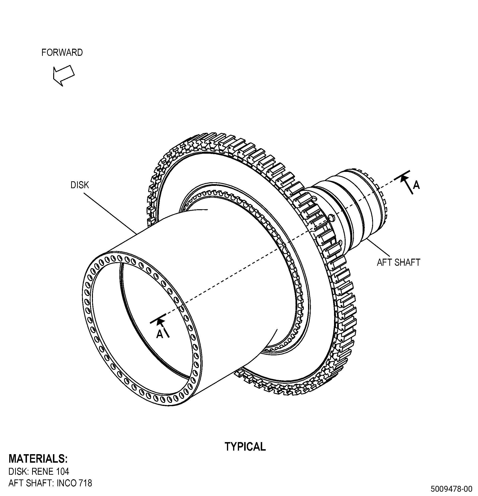
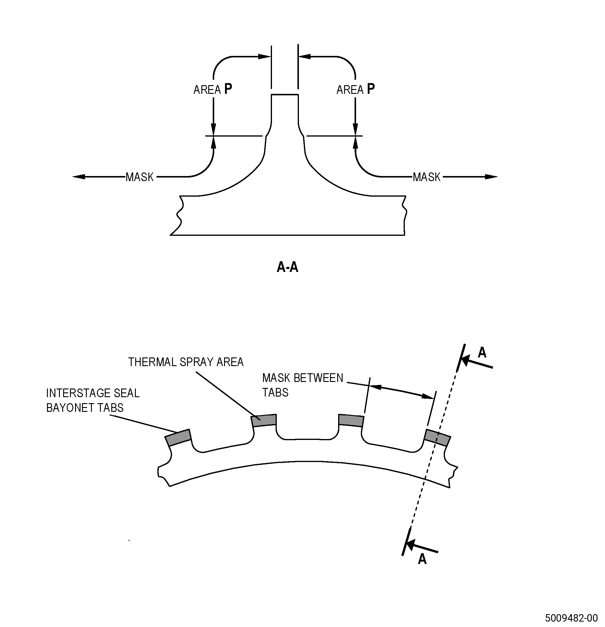
| A. | This procedure gives instructions to repair the HPT rotor stage 1 disk (disk) by thermal spraying the worn bayonet tabs. Refer to Figure 901. |
| B. | The following maximum repairable limits apply to this repair: |
| NOTE: |
|
| (4) | Visual Inspection. |
| (y) | Do an inspection of the interstage seal disk ID bayonet. Refer to Figure 812 and as follows: |
| 3 | Wear on tab mounting faces of the interstage seal bayonet: |
| Maximum repairable limit: |
|
| C. | The subsequent table gives a list of the part numbers that are applicable to this repair. All part numbers are applicable to all paragraphs unless specified differently. |
|
|||||||||||||||||||||||
| D. | Proprietary/Complex Process Statement. |
| (1) | None. |
| 2 . | Tools, Equipment, and Materials. |
| NOTE: |
|
| A. | Tools and Equipment. |
| (1) | Special Tools. None. |
| (2) | Standard Tools and Equipment. None. |
| (3) | Locally Manufactured Tools. None. |
| B. | Consumable Materials. |
| C. | Referenced Procedures. |
|
| D. | Expendable Parts. |
| None. |
| E. | SPD Information. |
| (1) | Locally Manufactured SPD. None. |
| F. | Special Solutions. |
| None. |
| G. | Test Specimens. |
| Refer to TASK 70-49-32-340-033 (THERMAL SPRAYING INCONEL 718 (POWDER)). |
| 3 . | Dimensional Information. |
| Subtask 72-53-40-220-194 |
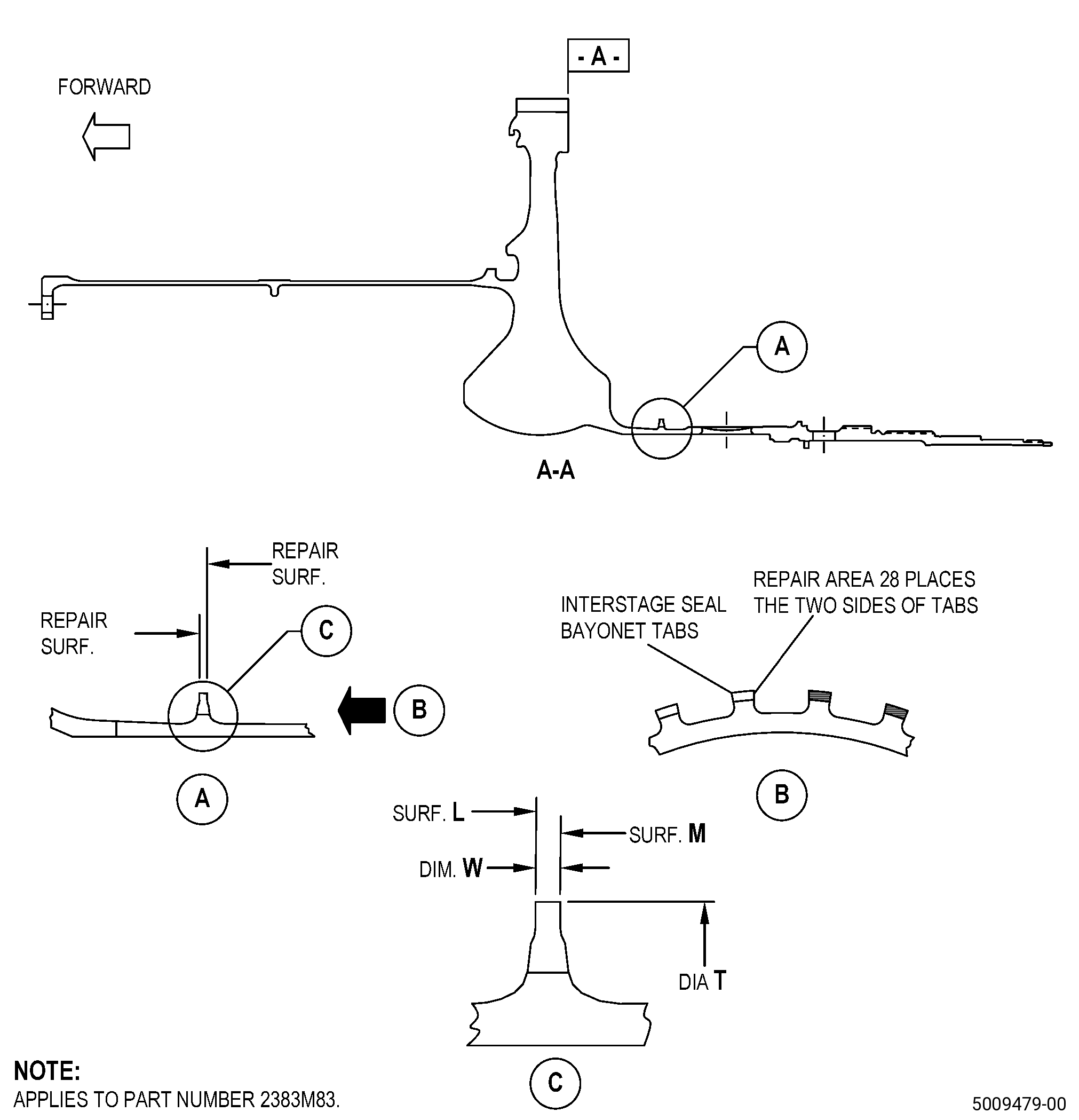
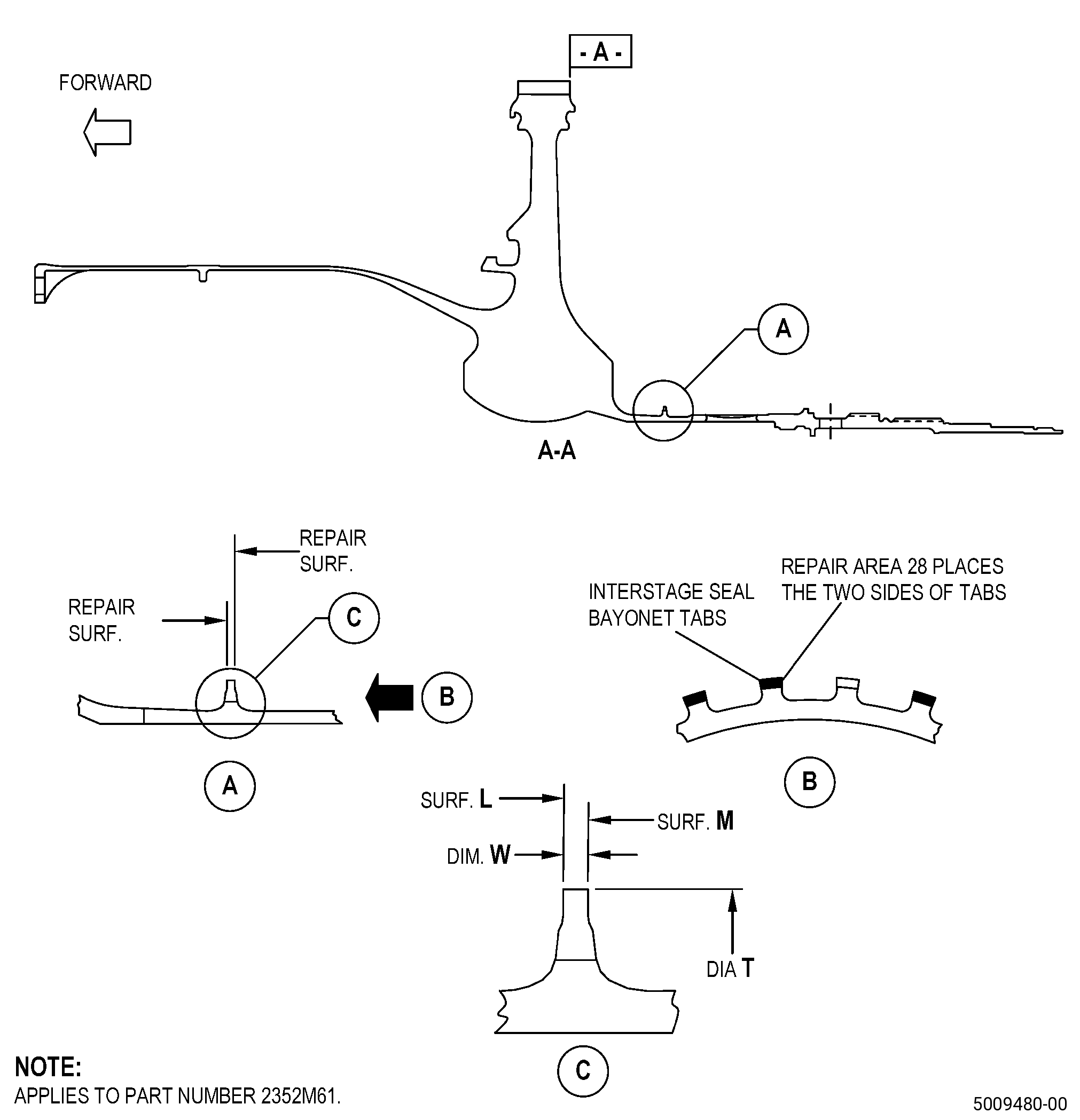
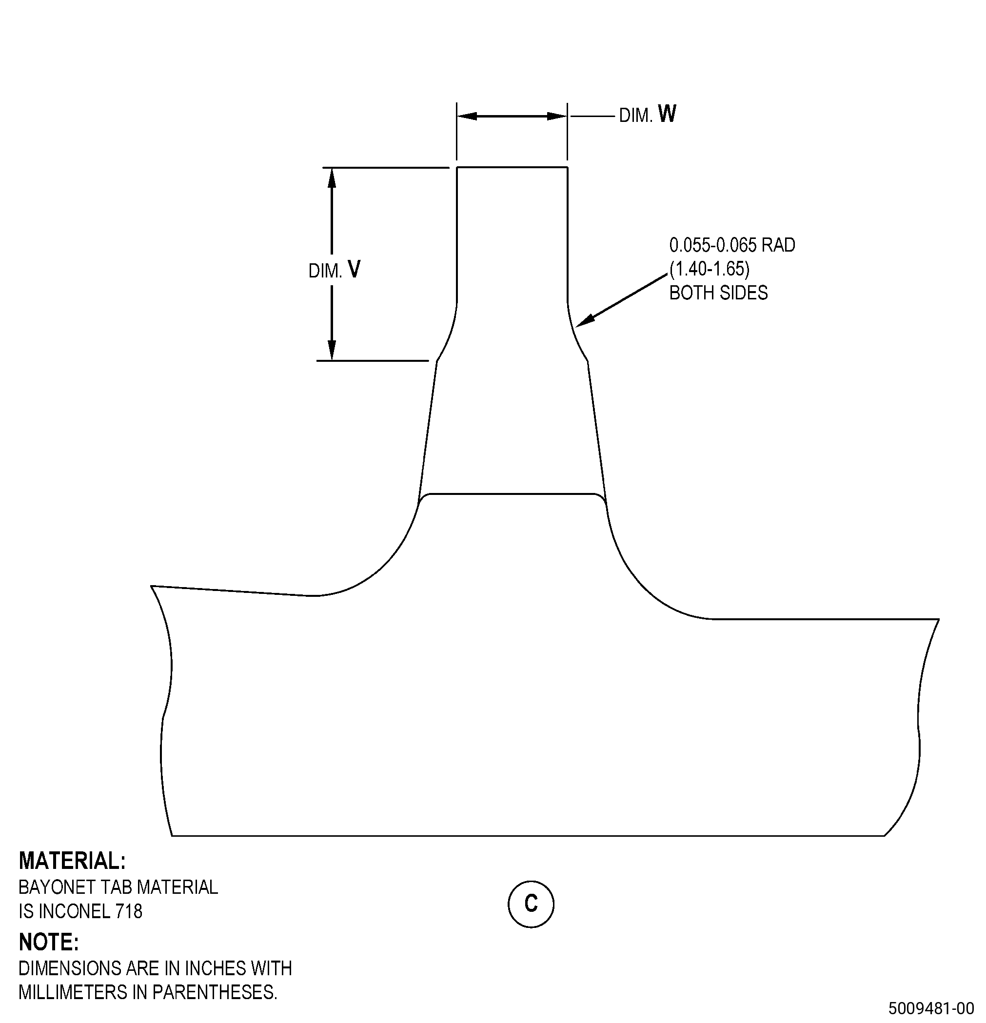
| A. | Refer to Figure 901, Figure 902, and Figure 904 for specified dimensions and locations. |
| NOTE: |
|
| NOTE: |
|
|
| 4 . | Setup Information. |
| Subtask 72-53-40-350-004 |
| A. | Set-up the disk for machining. Refer to Figure 901 and as follows: |
| (1) | Surface A runout to the machine table face must be 0.002 inch (0.05 mm) or less. |
| (2) | The concentricity of diameter T to the machine table centerline must be 0.001 inch (0.02 mm) or less. |
| 5 . | Procedure. |
| Subtask 72-53-40-320-001 |
| A. | Machine the disk. Refer to TASK 70-00-03-800-004 (MACHINING DATA), Figure 901, Figure 902, and as follows: |
| (1) | Set-up the disk for machining. Refer to Subtask 72-53-40-350-004 (paragraph 4.A.). |
| (2) | Machine surface L and/or surface M as follows: |
| (a) | Fully remove wear, galling, and thermal spray coating. |
| (b) | Remove sufficient parent material to let a minimum of 0.004 inch (0.11 mm) of thermal spray coating is on each repaired surface. |
| (c) | Make sure that surface L and surface M agree with the in-process dimensions in Subtask 72-53-40-220-194 (paragraph 3.A.). |
| (3) | Surface finish of the machined surfaces must be 63 microinches (1.6 micrometers) or better. |
| Subtask 72-53-40-350-005 |
| (4) | Blend the disk machined areas. Refer to TASK 70-42-00-350-002 (BLENDING AND REMOVAL OF HIGH METAL PROCEDURES) and as follows: |
| (a) | Break the sharp edges to 0.005-0.015 inch (0.13-0.38 mm). |
| Subtask 72-53-40-110-008 |
| (5) | Clean the disk. Refer to TASK 72-53-40-100-801 (72-53-40, CLEANING 001). |
| Subtask 72-53-40-110-009 |
| B. | Etch the machined areas of the disk. Refer to TASK 70-24-00-110-033 (ETCHING PROCEDURES FOR FLUORESCENT-PENETRANT INSPECTION), TASK 70-24-01-110-034 (SWAB ETCHING PROCEDURE), and as follows: |
| (1) | Use Class C etchant or Class G etchant. |
| Subtask 72-53-40-230-009 |
| C. | Do an inspection of the disk machined areas. Refer to TASK 70-32-00-200-002 (INDIRECT INSPECTION METHODS), TASK 70-32-03-230-002 (SPOT-FLUORESCENT-PENETRANT INSPECTION), and as follows: |
| (1) | Use Class G penetrant. |
| (2) | Indications less than 0.015 inch (0.38 mm) are not interpretable as linear indications and are permitted. |
| (3) | Indications more than 0.015 inch (0.38 mm) are not permitted. |
| Subtask 72-53-40-380-003 |
| D. | Peen the machined areas of the disk. Refer to TASK 70-47-01-380-016 (SHOTPEENING), Figure 901, Figure 902, and as follows: |
| (1) | If necessary, apply C10-021 plastic tape to the threads and the splines. Overspray is permitted, but not on splines or threads. |
| (2) | Use C04-166 CCW14 steel shot. |
| (3) | Peen to an intensity of 0.006-0.012N. |
| (4) | Coverage must be a minimum of 125 percent. |
| Subtask 72-53-40-340-001 |
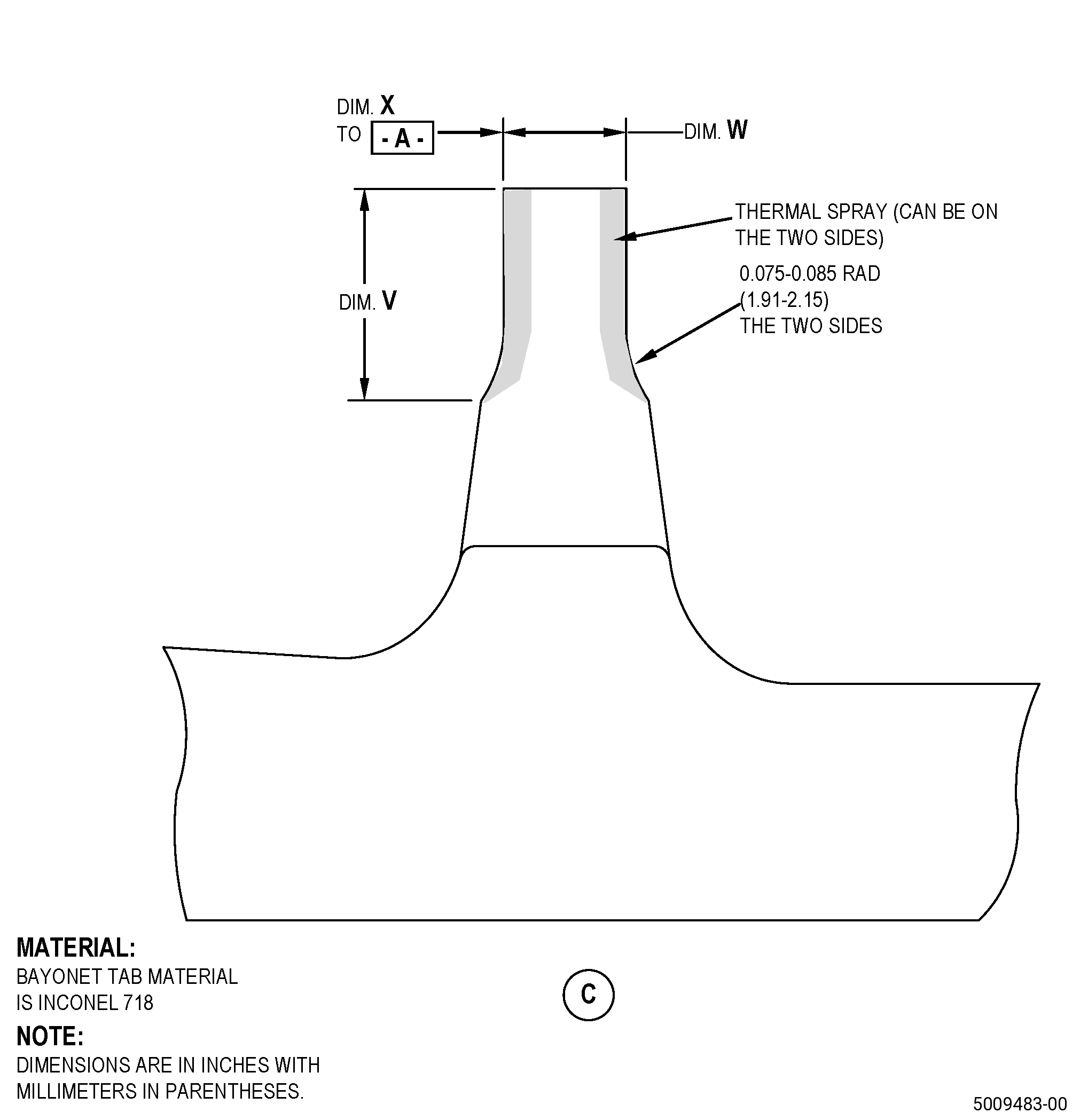
| E. | Thermal-spray the disk machined areas and the test specimens. Refer to TASK 70-49-00-340-001 (THERMAL SPRAYING), TASK 70-49-32-340-033 (THERMAL SPRAYING INCONEL 718 (POWDER)), Subtask 72-53-40-220-194 (paragraph 3.A.), Figure 903, and as follows: |
| NOTE: |
|
| (1) | Apply C10-012 masking tape to areas adjacent to area P. Overspray is only permitted on diameter T. |
| (2) | Prepare the surfaces of area P and the test specimens as follows: |
| (a) | Grit-blast area P on the disk and the test specimens to the surface roughness limits for nickel based materials. |
| (3) | Apply sufficient thermal spray coating layer to area P and the test specimens that will let area P agree with the finish dimensional limits and as follows: |
| NOTE: |
|
| (a) | The maximum coating thickness after thermal-spray must be less than 0.025 inch (0.63 mm). |
| (b) | The minimum thermal spray coating thickness must be 0.004 inch (0.11 mm) after finish machining. |
| (4) | Do the quality assurance testing on the test specimens. |
| CAUTION: |
|
| (5) | Remove the masking material from the disk. |
| Subtask 72-53-40-320-002 |
| F. | Machine the disk. Refer to TASK 70-00-03-800-004 (MACHINING DATA), Subtask 72-53-40-220-194 (paragraph 3.A.), Figure 904, and as follows: |
| (1) | Set-up the disk for machining. Refer to Subtask 72-53-40-350-004 (paragraph 4.A.). |
| (2) | Machine the disk thermal sprayed areas to the finished dimensions. |
| (3) | If you thermal sprayed diameter T, machine diameter T to the parent material to remove all thermal spray. Diameter T must agree with the limits specified in Subtask 72-53-40-220-194 (paragraph 3.A.). |
| (4) | The minimum coating thickness after machining must be 0.004 inch (0.11 mm). |
| (5) | Dimension V at finish machining must be equal to dimension V at in-process machining to plus or minus 0.002 (0.05 mm). Dimension V must agree with the limits specified in Subtask 72-53-40-220-194 (paragraph 3.A.). |
| Subtask 72-53-40-350-006 |
| (6) | Blend the disk machined areas. Refer to TASK 70-42-00-350-002 (BLENDING AND REMOVAL OF HIGH METAL PROCEDURES) and do as follows: |
| (a) | Break the sharp edges to 0.005-0.015 inch (0.13-0.38 mm). |
| (b) | Hand-polish all the remaining thermal spray coating. |
| (c) | Shotpeening not required after blending and polishing. |
| (7) | Surface finish of the machined surfaces must be 63 microinches (1.6 micrometers) or better. |
| Subtask 72-53-40-110-010 |
| (8) | Clean the disk. Refer to TASK 72-53-40-100-801 (72-53-40, CLEANING 001). |
| Subtask 72-53-40-220-195 |
| (9) | Do a visual inspection of the machined thermal spray coating and as follows: |
| (a) | No chipping, flaking, or spalling is permitted. |