| GENX-1B CLEANING,INSPECTION,AND REPAIR MANUAL | Dated: 10/31/2019 | |
| CIR 72-58-40 , REPAIR 010 | ||
| MID FAN SHAFT - REPAIR - THERMAL SPRAY REPAIR OF THE CENTER VENT DUCT MATING SURFACES | ||
| GENX-1B CLEANING,INSPECTION,AND REPAIR MANUAL | Dated: 10/31/2019 | |
| CIR 72-58-40 , REPAIR 010 | ||
| MID FAN SHAFT - REPAIR - THERMAL SPRAY REPAIR OF THE CENTER VENT DUCT MATING SURFACES | ||
| * * * FOR ALL |
| TASK 72-58-40-300-808 |
| 1 . | Thermal Spray Repair of the Center Vent Duct Mating Surfaces. |
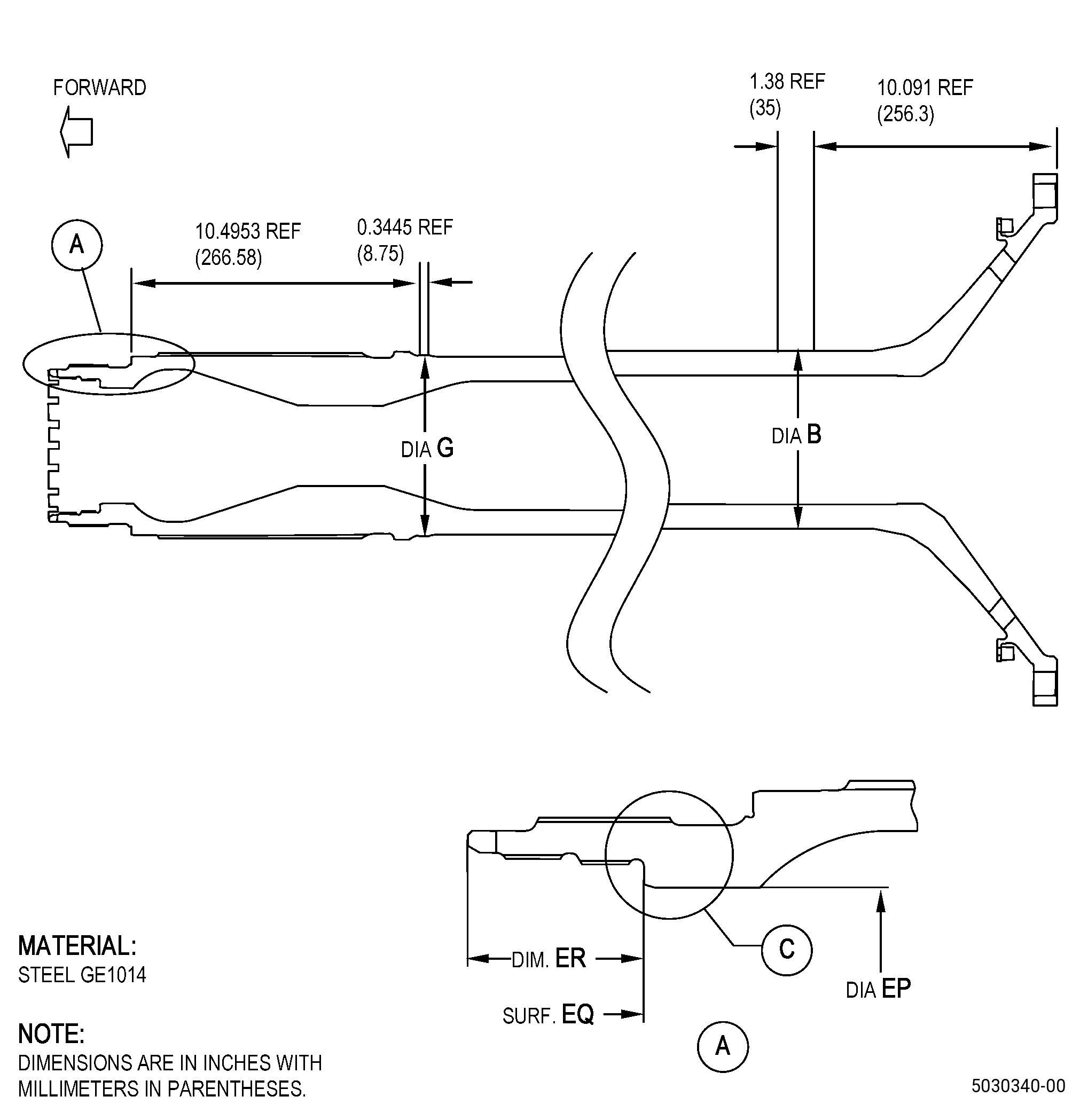
| A. | This procedure gives instructions to repair the mid fan shaft (shaft) by thermal spraying the center vent duct mating surfaces (diameter EP and surface EQ). Refer to Figure 901. |
| B. | The following maximum repairable limits apply to this repair: |
| NOTE: |
|
| (4) | Visual Inspection. |
| (q) | Do an inspection of the center vent duct mating surface (surface EQ) for: |
| 2 | Nicks, dents, or scratches: |
| Maximum repairable limit: |
|
| 3 | Contact mark: |
| Maximum repairable limit: |
|
| 4 | Fretting or corrosion pits: |
| Maximum repairable limit: |
|
| (q).A. | Do an inspection of the center vent duct mating surface (diameter EP) for: |
| 2 | Nicks, dents, or scratches on diameter EP: |
| Maximum repairable limit: |
|
| 3 | Contact mark: |
| Maximum repairable limit: |
|
| 4 | Fretting or corrosion pits: |
| Maximum repairable limit: |
|
| C. | The subsequent table gives a list of the part numbers that are applicable to this repair. All part numbers are applicable to all paragraphs unless specified differently. |
|
||||||||||||||||||||||||||||||||||||
| D. | Proprietary/Complex Process Statement. |
| (1) | None. |
| 2 . | Tools, Equipment, and Materials. |
| NOTE: |
|
| A. | Tools and Equipment. |
| (1) | Special Tools. None. |
| (2) | Standard Tools and Equipment. None. |
| (3) | Locally Manufactured Tools. None. |
| B. | Consumable Materials. |
|
| C. | Referenced Procedures. |
| D. | Expendable Parts. None. |
| E. | SPD Information. |
| (1) | Locally Manufactured SPD. None. |
| F. | Special Solutions. None. |
| G. | Test Specimens. Refer to TASK 70-49-21-340-022 (THERMAL SPRAYING NICKEL-CHROMIUM/ALUMINUM COMPOSITE (POWDER)) . |
| 3 . | Dimensional Information. |
| Subtask 72-58-40-220-110 |
| A. | Refer to Figure 901 for specified dimensions and locations. |
| NOTE: |
|
| NOTE: |
|
|
| 4 . | Setup Information. |
| Subtask 72-58-40-350-038 |
| A. | Set-up the shaft for machining. Refer to Figure 901 and as follows: |
| Subtask 72-58-40-220-111 |
| (1) | Make sure that diameter G runout is 0.0011 inch (0.03 mm) or less. |
| (2) | Make sure that diameter B runout is 0.0011 inch (0.03 mm) or less. |
| 5 . | Procedure. |
| Subtask 72-58-40-160-004 |
| A. | If necessary, clean the shaft. Refer to TASK 70-21-00-110-051 (CHEMICAL CLEANING) and TASK 70-21-03-160-001 (CLEANING METHOD NO. 3 - STEAM CLEANING). |
| Subtask 72-58-40-320-006 |
| B. | Machine the shaft diameter EP/surface EQ. Refer to TASK 70-00-03-800-004 (MACHINING DATA), Subtask 72-58-40-220-110 (paragraph 3.A.), Figure 901, Figure 902, and as follows: |
| Subtask 72-58-40-220-115 |
| (1) | For tolerances and general instructions, which include visual inspection after machining. Refer to TASK 70-31-06-220-001 (MACHINED FEATURES SHOP-RUN TOLERANCES). |
| Subtask 72-58-40-350-039 |
| (1) | Set-up the shaft for machining. Refer to Subtask 72-58-40-350-038 (paragraph 4.A.). |
| Subtask 72-58-40-320-007 |
| (1) | Machine diameter EP/surface EQ to the in-process dimensions to remove all damage/remaining thermal spray coating. |
| (2) | Break the machined edges and sharp corners to 0.00500-0.01500 inch (0.127-0.381 mm). |
| Subtask 72-58-40-350-040 |
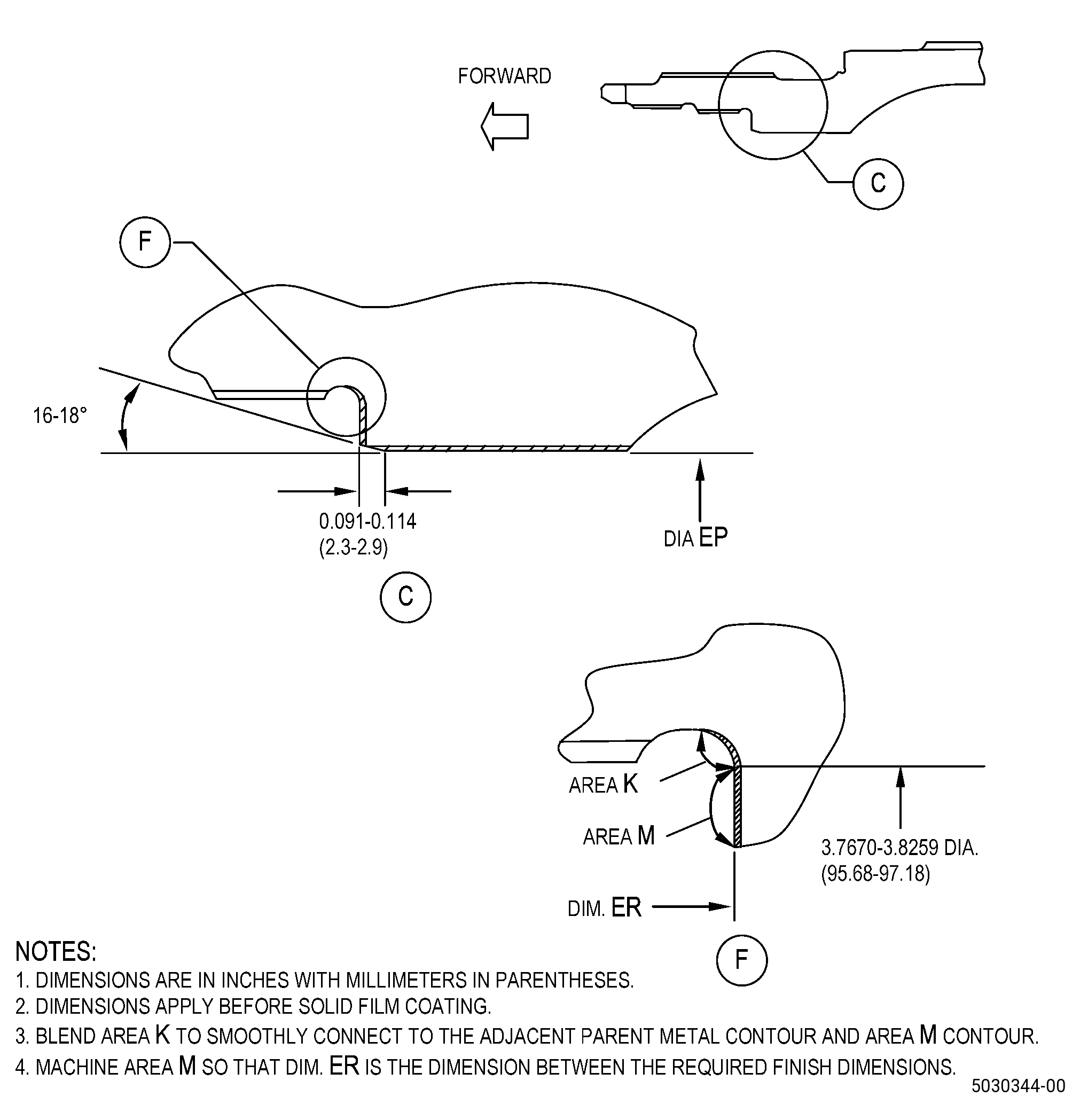
| C. | If necessary, blend the shaft machined area. Refer to TASK 70-42-00-350-002 (BLENDING AND REMOVAL OF HIGH METAL PROCEDURES), Figure 902, and as follows: |
| (1) | Remove burrs and rolled edges from the shaft. |
| Subtask 72-58-40-220-112 |
| D. | Do a dimensional inspection of the shaft diameter EP/surface EQ. Refer to Subtask 72-58-40-220-110 (paragraph 3.A.), Figure 901, and as follows: |
| (1) | If diameter EP/surface EQ does not agree with the in-process dimensions, you cannot repair the shaft with this procedure. |
| Subtask 72-58-40-240-004 |
| E. | Alternative Procedure Available. Do a magnetic-particle inspection of the shaft machined areas. Refer to TASK 72-58-40-200-801 (72-58-40, INSPECTION 001), and Figure 902, and as follows: |
| (1) | Indications are not permitted. |
| Subtask 72-58-40-220-113 |
| E.A. | Alternative Procedure. Do an inspection of the shaft machined areas. Refer to Figure 902 and as follows: |
| Subtask 72-58-40-110-010 |
| (1) | Etch the shaft machined areas. Refer to TASK 70-24-00-110-033 (ETCHING PROCEDURES FOR FLUORESCENT-PENETRANT INSPECTION), TASK 70-24-01-110-034 (SWAB ETCHING PROCEDURE), and as follows: |
| (a) | Use Class C etchant. |
| Subtask 72-58-40-230-001 |
| (2) | Do an inspection of the shaft machined areas. Refer to TASK 70-32-00-200-002 (INDIRECT INSPECTION METHODS), TASK 70-32-03-230-002 (SPOT-FLUORESCENT-PENETRANT INSPECTION), and as follows: |
| (a) | Use Class G penetrant. |
| (b) | Indications are not permitted. |
| Subtask 72-58-40-380-016 |
| F. | Peen the shaft machined areas. Refer to TASK 70-47-01-380-016 (SHOTPEENING), Figure 901, Figure 902, and as follows: |
| (1) | Use S170 maximum C04-271 high hardness cast steel shot. |
| (2) | Intensity must be 0.010 to 0.015A. |
| (3) | Use a simulative fixture. |
| (4) | Shotpeen overspray is permitted but not on the threaded or coated areas. |
| (5) | Minimum of 100 percent coverage is required. |
| Subtask 72-58-40-340-001 |
| G. | Thermal-spray the shaft machined areas and the test specimens. Refer to TASK 70-49-00-340-001 (THERMAL SPRAYING), TASK 70-49-21-340-022 (THERMAL SPRAYING NICKEL-CHROMIUM/ALUMINUM COMPOSITE (POWDER)), Figure 903, and as follows: |
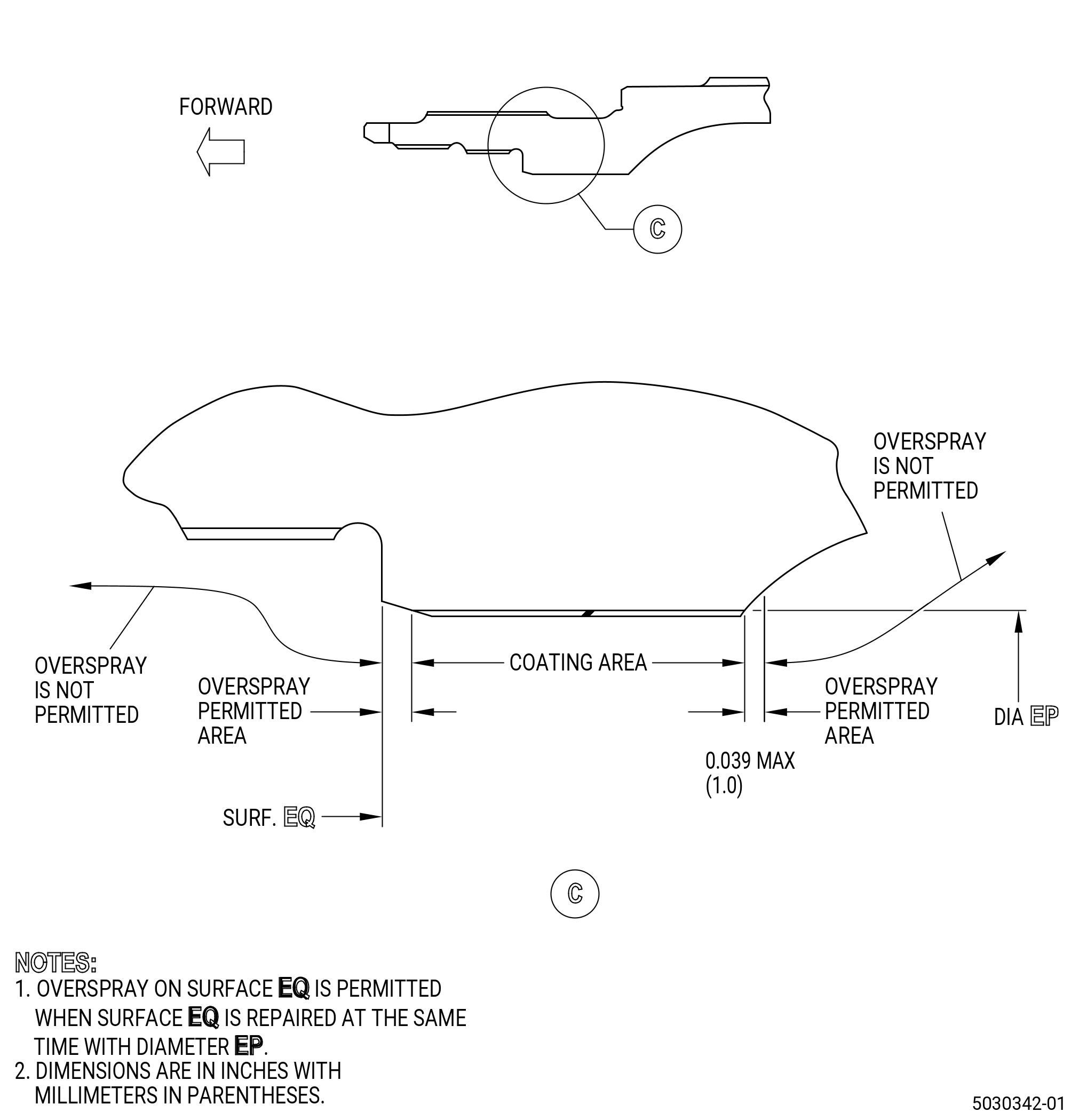
| (1) | Maximum as sprayed coating thickness must not be more than 0.039 inch (1.0 mm). |
| Subtask 72-58-40-320-008 |
| H. | Machine the shaft to the finish dimensions. Refer to TASK 70-00-03-800-004 (MACHINING DATA), Subtask 72-58-40-220-110 (paragraph 3.A.), Figure 901, Figure 904, and as follows: |
| (1) | For tolerances, refer to TASK 70-31-06-220-001 (MACHINED FEATURES SHOP-RUN TOLERANCES). |
| Subtask 72-58-40-350-041 |
| (2) | Set-up the shaft for machining. Refer to Subtask 72-58-40-350-038 (paragraph 4.A.). |
| Subtask 72-58-40-320-009 |
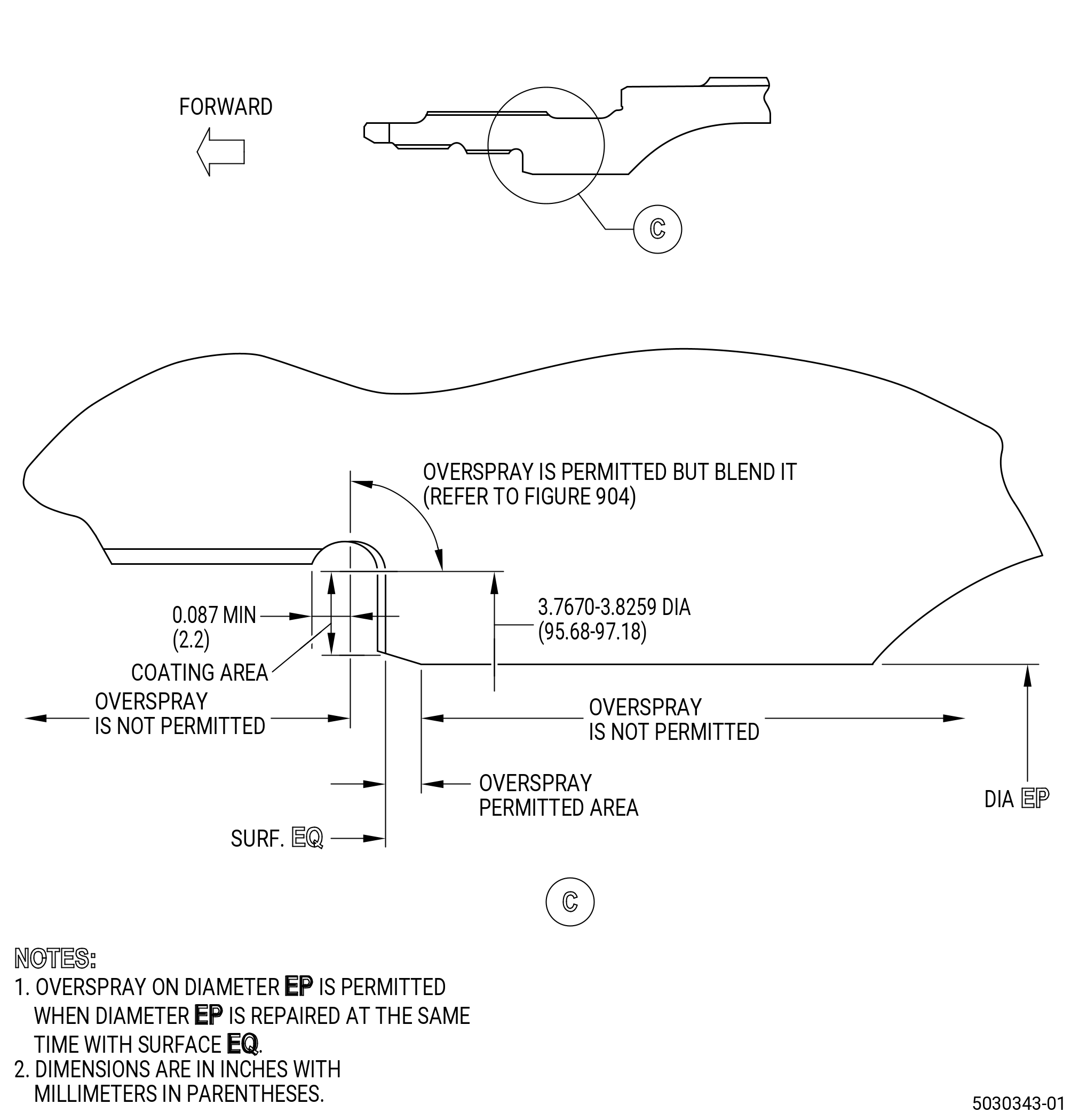
| (3) | Machine diameter EP/surface EQ to the finish dimensions. |
| (4) | For part number 2331M20G03 , break sharp edges to 0.004-0.019 inch (0.1-0.5 mm). |
| (5) | For part number 2332M81G03 and part number 2332M81G04 , break sharp edges to 0.0100 inch (0.254 mm) maximum. |
| Subtask 72-58-40-350-042 |
| CAUTION: |
|
| I. | Blend the shaft. Refer to TASK 70-42-00-350-002 (BLENDING AND REMOVAL OF HIGH METAL PROCEDURES), Figure 903, Figure 904, and as follows: |
| NOTE: |
|
| (1) | Make a smooth contour of the thermal sprayed area with the adjacent surface. |
| (2) | Maximum blend depth of base metal at overspray coating removal is 0.00098 inch (0.025 mm). |
| Subtask 72-58-40-220-114 |
| J. | Do a visual inspection of the shaft repaired area as follows: |
| (1) | Spalling, chipping, cracking, or separation of the thermal spray coating is not permitted. |