| GENX-1B CLEANING,INSPECTION,AND REPAIR MANUAL | Dated: 10/31/2016 | |
| CIR 72-58-45 , REPAIR 001 | ||
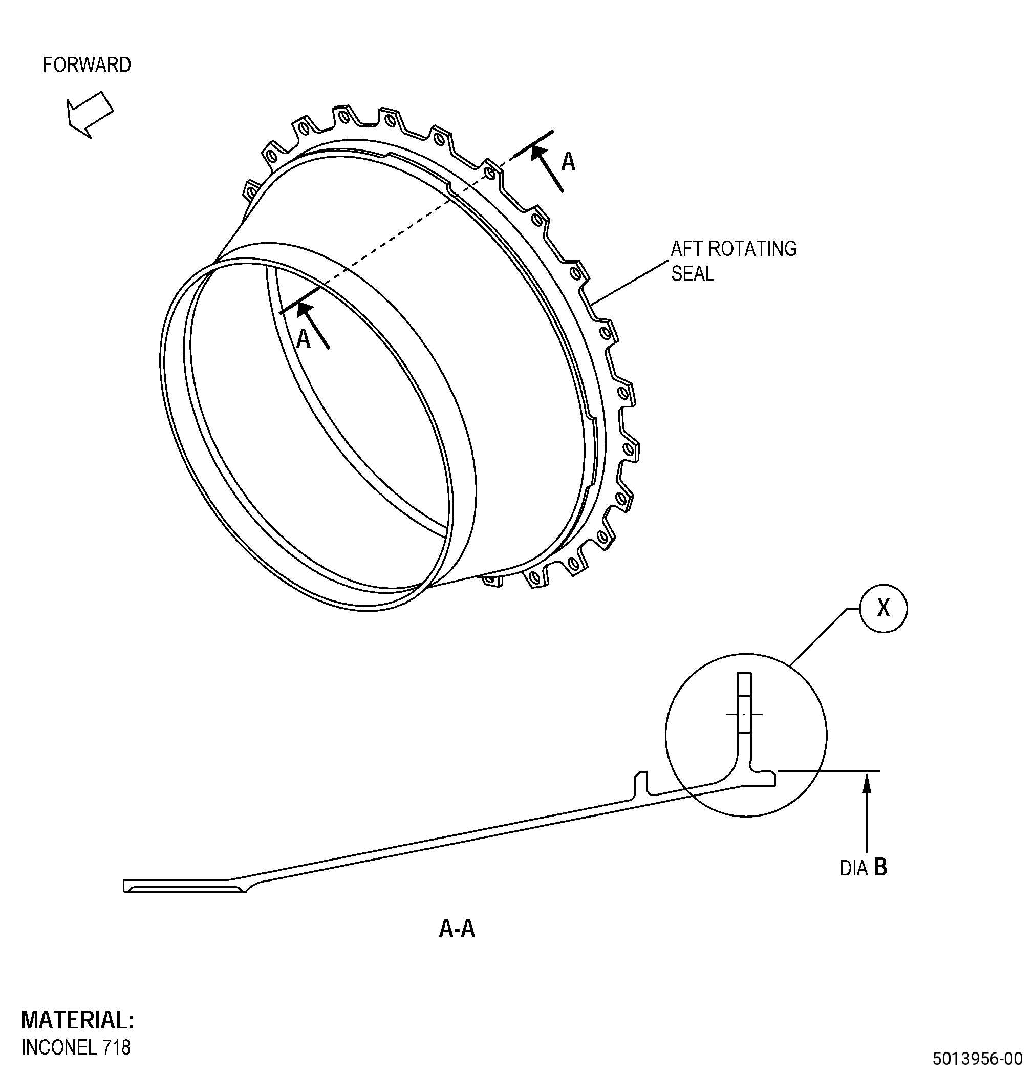
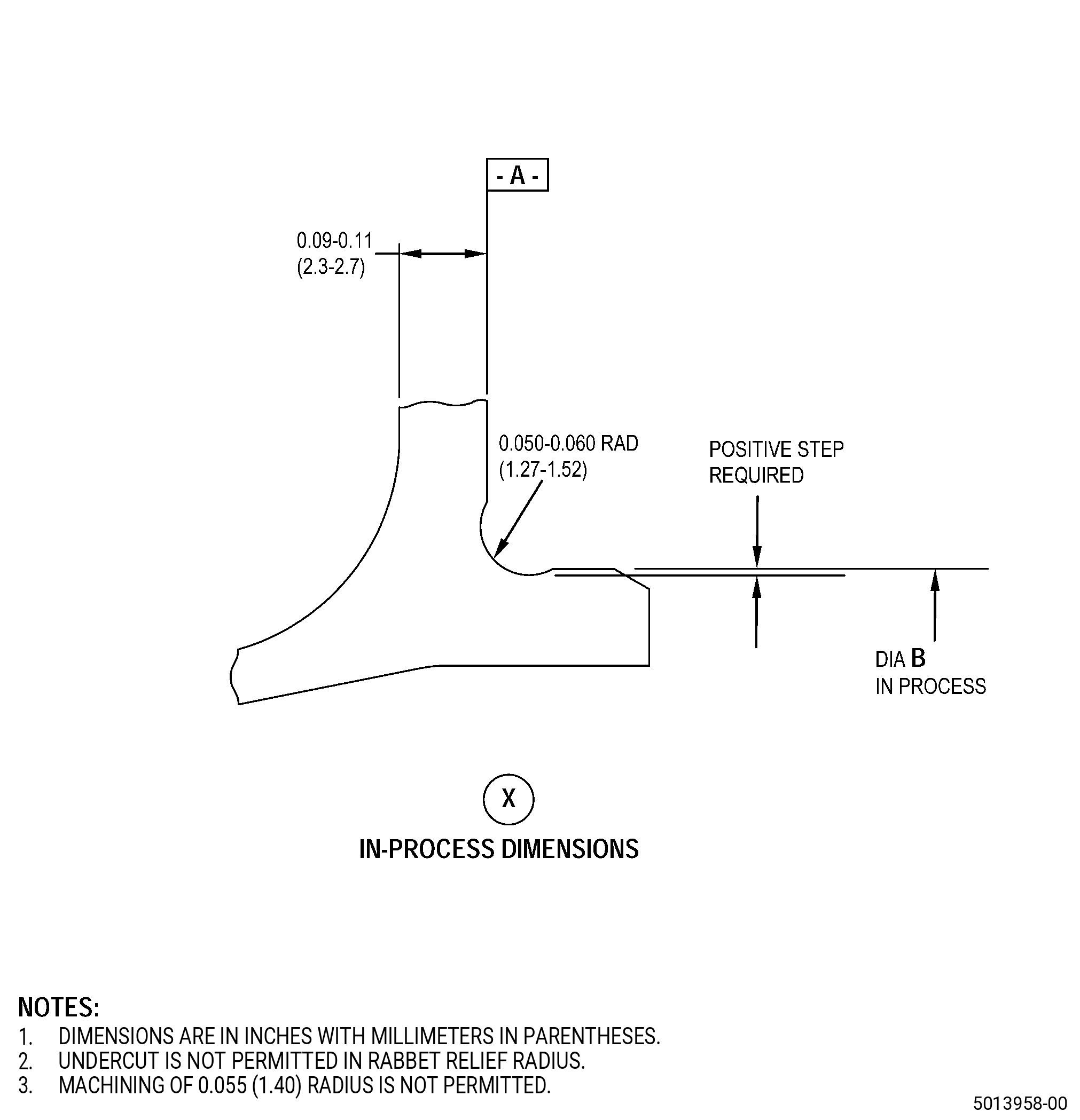
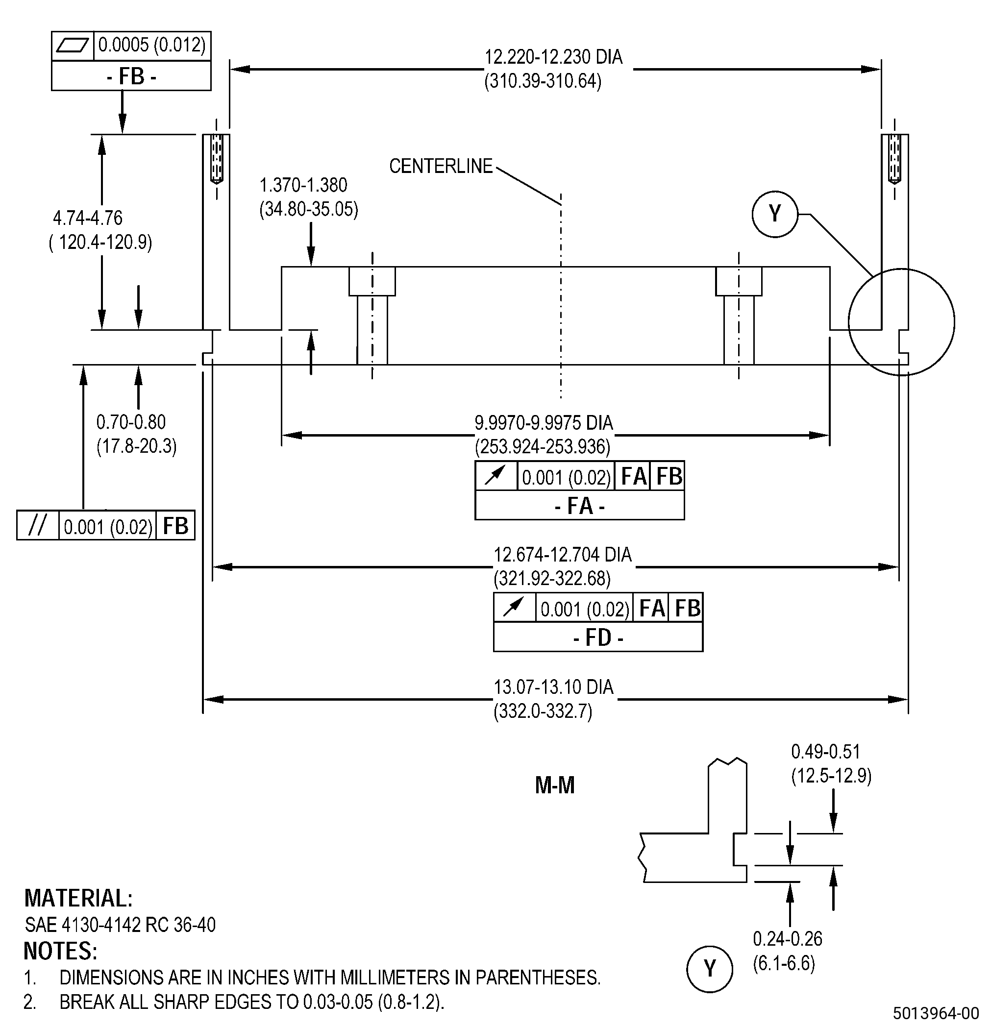
| NO. 4 BEARING AFT ROTATING SEAL - REPAIR - REPAIR OF THE RABBET DIAMETER B | ||
| GENX-1B CLEANING,INSPECTION,AND REPAIR MANUAL | Dated: 10/31/2016 | |
| CIR 72-58-45 , REPAIR 001 | ||
| NO. 4 BEARING AFT ROTATING SEAL - REPAIR - REPAIR OF THE RABBET DIAMETER B | ||
| * * * FOR ALL |
| TASK 72-58-45-300-802 |
| 1 . | Repair of the Rabbet Diameter B. |
| A. | This procedure gives instructions to repair the No. 4 bearing aft rotating seal (aft rotating seal) by thermal spraying the rabbet diameter B. Refer to Figure 901. |
| B. | The following maximum repairable limits apply to this repair: |
| NOTE: |
|
| NOTE: |
|
| (5) | Dimensional Inspection. |
| (d) | Do an inspection of the aft rotating seal for: |
| 1 | Diameter B (free state): |
| Maximum repairable limit: |
|
| C. | The subsequent table gives a list of the part numbers that are applicable to this repair. All part numbers are applicable to all paragraphs unless specified differently. |
|
|||||||||||||||||||||||
| D. | Proprietary/Complex Process Statement. |
| (1) | None. |
| 2 . | Tools, Equipment, and Materials. |
| NOTE: |
|
| A. | Tools and Equipment. |
| (1) | Special Tools. None. |
| (2) | Standard Tools and Equipment. None. |
| (3) | Locally Manufactured Tools. |
|
| B. | Consumable Materials. |
| C. | Referenced Procedures. |
|
| D. | Expendable Parts. None. |
| E. | SPD Information. |
| (1) | Locally Manufactured SPD. None. |
| F. | Special Solutions. None. |
| G. | Test Specimens. Refer to TASK 70-49-32-340-033 (THERMAL SPRAYING INCONEL 718 (POWDER)) . |
| 3 . | Dimensional Information. |
| Subtask 72-58-45-220-027 |
| A. | Refer to Figure 901 and Figure 905 for specified dimensions and locations. |
| NOTE: |
|
| NOTE: |
|
|
| 4 . | Setup Information. |
| Subtask 72-58-45-350-009 |
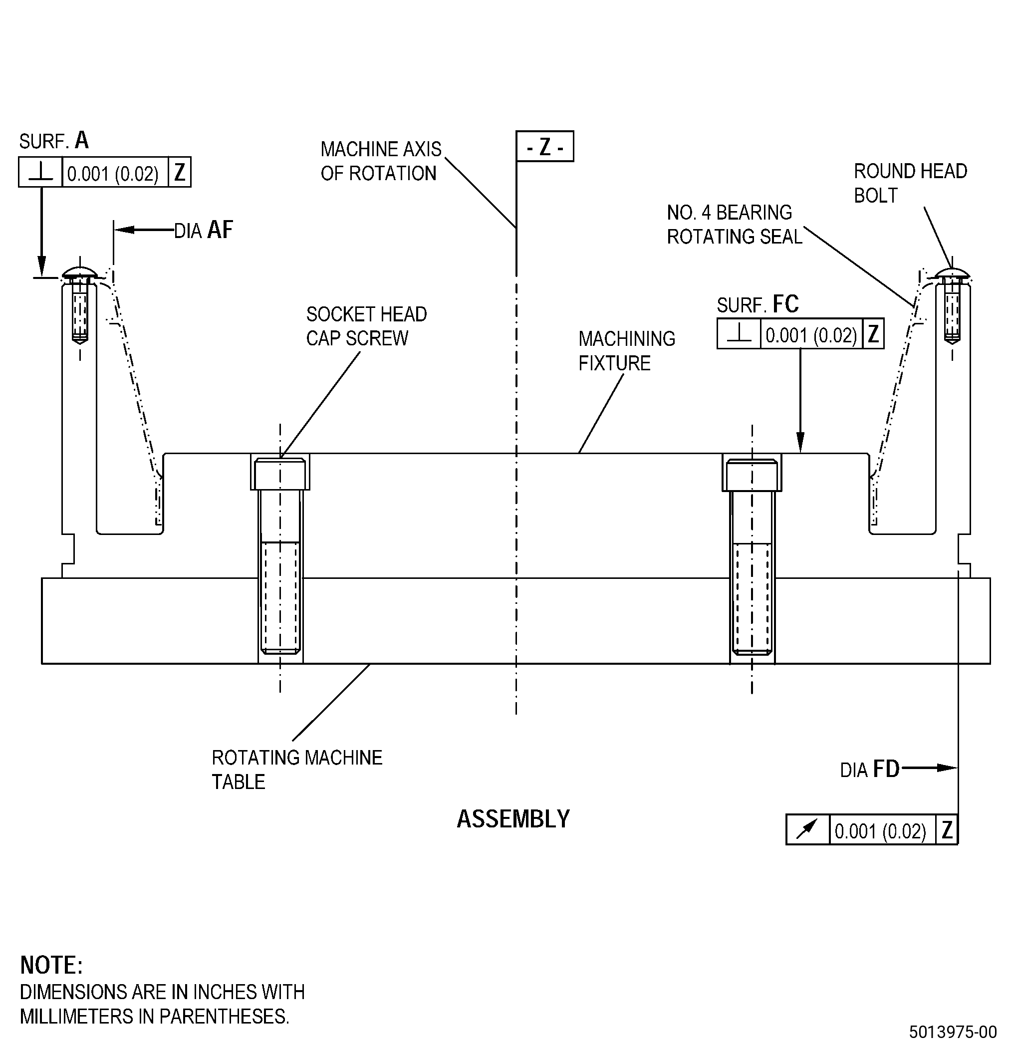
| A. | Set-up the aft rotating seal for machining. Refer to Figure 903 and as follows: |
| Subtask 72-58-45-930-002 |
| (1) | If necessary, make the machining fixture. Refer to Figure 902. |
| Subtask 72-58-45-350-010 |
| (2) | Put the machining fixture on the rotating machine table as follows: |
| Subtask 72-58-45-220-034 |
| (a) | Surface FC must be perpendicular to 0.001 inch (0.02 mm) or less to the machine axis of rotation. |
| (b) | The runout of diameter FD must be 0.001 inch (0.02 mm) or less, full indicator reading (FIR) to the machine axis of rotation. |
| Subtask 72-58-45-350-016 |
| (3) | Attach the machining fixture to the rotating machine table with socket head cap screws. |
| (4) | Attach the aft rotating seal on the machining fixture/rotating machine table assembly as follows: |
| Subtask 72-58-45-220-035 |
| (a) | Surface A must be perpendicular to 0.001 inch (0.02 mm) or less to the machine axis of rotation. |
| (b) | The runout of diameter AF must be 0.001 inch (0.02 mm) or less, FIR to the machine axis of rotation. |
| Subtask 72-58-45-350-017 |
| (5) | Attach the aft rotating seal to the machining fixture with round head bolts. |
| NOTE: |
|
| 5 . | Procedure. |
| Subtask 72-58-45-220-028 |
| A. | Do a visual inspection of the aft rotating seal diameter B for Inconel 718 plasma spray coating or parent material. Refer to Figure 901 and as follows: |
| (1) | If there is Inconel 718 plasma spray coating on the surface of diameter B, go to Subtask 72-58-45-330-003 (paragraph 5.B.). |
| (2) | If there is no Inconel 718 plasma spray coating on the surface of diameter B, go to Subtask 72-58-45-320-005 (paragraph 5.D.), to prepare the aft rotating seal for thermal spraying. |
| Subtask 72-58-45-330-003 |
| B. | Alternative Procedure Available. Remove the Inconel 718 plasma spray coating from the aft rotating seal diameter B. Refer to TASK 70-23-00-100-001 (STRIPPING PROCEDURES), TASK 70-23-23-330-008 (REMOVAL OF COATINGS BY HIGH PRESSURE WATER STRIPPING), Figure 901, and as follows: |
| (1) | Make sure to remove all the Inconel 718 plasma spray coating from diameter B. |
| Subtask 72-58-45-220-032 |
| (2) | Do a visual inspection of diameter B for parent metal wear after removal of Inconel 718 plasma spray coating as follows: |
| (a) | If diameter B has parent metal wear, go to Subtask 72-58-45-320-005 (paragraph 5.D.). |
| (b) | If diameter B does not have parent metal wear, go to Subtask 72-58-45-220-033 (paragraph 5.C.). |
| Subtask 72-58-45-320-004 |
| CAUTION: |
|
| B.A. | Alternative Procedure. Machine the aft rotating seal diameter B to remove the previous Inconel 718 plasma spray coating and prepare it for thermal spraying. Refer to TASK 70-00-03-800-004 (MACHINING DATA), Subtask 72-58-45-220-027 (paragraph 3.A.), Figure 901, and as follows: |
| (1) | Go to Subtask 72-58-45-320-005 (paragraph 5.D.). |
| Subtask 72-58-45-220-033 |
| C. | Do a dimensional inspection of the aft rotating seal diameter B. Refer to Subtask 72-58-45-220-027 (paragraph 3.A.), Figure 901, and as follows: |
| (1) | The average diameter B must agree with the in-process dimensions. |
| (2) | Measure diameter B at eight locations with an equal distance between each location, around the aft rotating seal. |
| (3) | Calculate the average of the eight dimensions. |
| (4) | If diameter B agrees with the in-process dimensions, go to Subtask 72-58-45-160-008 (paragraph 5.E.), for thermal spraying. |
| (5) | If diameter B is more than the in-process dimensions, go to Subtask 72-58-45-320-005 (paragraph 5.D.), to prepare diameter B for thermal spraying. |
| (6) | If the average of diameter B is less than the minimum in-process, you cannot repair the aft rotating seal with this procedure. |
| Subtask 72-58-45-320-005 |
| CAUTION: |
|
| CAUTION: |
|
| D. | Machine the aft rotating seal diameter B to remove wear or initial thermal spray coating and prepare it for thermal spraying. Refer to TASK 70-00-03-800-004 (MACHINING DATA), Subtask 72-58-45-220-027 (paragraph 3.A.), Figure 901, and as follows: |
| Subtask 72-58-45-350-013 |
| (1) | Set-up the aft rotating seal for machining. Refer to Subtask 72-58-45-350-009 (paragraph 4.A.). |
| Subtask 72-58-45-320-006 |
| (2) | Machine diameter B to remove parent metal wear or all signs of remaining thermal spray coating as follows: |
| (a) | Make sure that you remove sufficient material to get a minimum coating thickness of 0.004 inch (0.11 mm) after final machining. |
| (b) | Deleted. |
| (3) | Make sure that you remove all the parent metal wear from diameter B and as follows: |
| (a) | If you cannot remove the parent metal wear from diameter B to agree with the minimum in-process dimensions, you cannot repair the aft rotating seal with this procedure. |
| Subtask 72-58-45-350-014 |
| (4) | If necessary, blend the machined diameter B of the aft rotating seal. Refer to TASK 70-42-00-350-002 (BLENDING AND REMOVAL OF HIGH METAL PROCEDURES) and as follows: |
| (a) | Remove all high metal and rolled edges. |
| (5) | Remove the aft rotating seal from the machining fixture. |
| Subtask 72-58-45-160-008 |
| E. | Clean the aft rotating seal. Refer to TASK 70-21-00-110-051 (CHEMICAL CLEANING) and TASK 70-21-03-160-001 (CLEANING METHOD NO. 3 - STEAM CLEANING). |
| Subtask 72-58-45-110-015 |
| F. | Etch the aft rotating seal diameter B. Refer to TASK 70-24-00-110-033 (ETCHING PROCEDURES FOR FLUORESCENT-PENETRANT INSPECTION), TASK 70-24-01-110-034 (SWAB ETCHING PROCEDURE), and as follows: |
| (1) | Use Class C etchant. |
| Subtask 72-58-45-230-004 |
| G. | Do an inspection of the aft rotating seal diameter B. Refer to TASK 70-32-00-200-002 (INDIRECT INSPECTION METHODS), TASK 70-32-03-230-002 (SPOT-FLUORESCENT-PENETRANT INSPECTION), and as follows: |
| (1) | Use Class G penetrant. |
| (2) | Refer to TASK 72-58-45-200-801 (72-58-45, INSPECTION 001) for the fluorescent penetrant inspection limits. |
| Subtask 72-58-45-160-009 |
| H. | Clean the aft rotating seal. Refer to TASK 70-21-00-110-051 (CHEMICAL CLEANING) and TASK 70-21-03-160-001 (CLEANING METHOD NO. 3 - STEAM CLEANING). |
| Subtask 72-58-45-380-001 |
| I. | Peen the aft rotating seal. Refer to TASK 70-47-01-380-016 (SHOTPEENING), Figure 904, and as follows: |
| (1) | Make sure to apply C10-021 plastic tape to all the surfaces adjacent to diameter B that you will not peen. |
| (2) | Use C04-271 S110 steel shot. |
| (3) | The peening intensity must be 0.006-0.012N in the repair area. |
| (4) | The minimum coverage must be 125 percent. |
| (5) | Remove the masking tape from the aft rotating seal. |
| Subtask 72-58-45-160-007 |
| J. | Clean the aft rotating seal. Refer to TASK 70-21-00-110-051 (CHEMICAL CLEANING) and TASK 70-21-03-160-001 (CLEANING METHOD NO. 3 - STEAM CLEANING). |
| Subtask 72-58-45-340-007 |
| K. | Thermal-spray the aft rotating seal and the test specimens. Refer to TASK 70-49-00-340-001 (THERMAL SPRAYING), TASK 70-49-32-340-033 (THERMAL SPRAYING INCONEL 718 (POWDER)), Subtask 72-58-45-220-027 (paragraph 3.A.), Figure 904, and as follows: |
| NOTE: |
|
| (1) | Make sure to apply C10-012 masking tape to all the surfaces adjacent to diameter B that you will not thermal spray. |
| (2) | Make sure that you do the preliminary operations specified in TASK 70-49-00-340-001 (THERMAL SPRAYING). |
| (a) | Use the surface roughness limits for the nickel base material. |
| (3) | Thermal-spray the aft rotating seal repair area and the test specimens as follows: |
| (a) | Apply a sufficient quantity of thermal spray coating to permit you to machine to get the finish dimensional limits. |
| (b) | The maximum as-sprayed coating thickness must be 0.015 inch (0.38 mm). |
| (c) | Apply thermal spray coating to the test specimens and to diameter B at the same time, same spray angle, and to the same thickness. |
| (d) | The minimum coating thickness after final machining must be 0.004 inch (0.11 mm). |
| (4) | Remove the masking tape from the aft rotating seal. |
| (5) | Do a tensile bond test and a metallographic examination of the coating on the test specimens. |
| Subtask 72-58-45-320-003 |
| L. | Machine the aft rotating seal diameter B to the finish dimensions. Refer to TASK 70-00-03-800-004 (MACHINING DATA), Subtask 72-58-45-220-027 (paragraph 3.A.), Figure 901, Figure 905, and as follows: |
| Subtask 72-58-45-350-015 |
| (1) | Set-up the aft rotating seal for machining. Refer to Subtask 72-58-45-350-009 (paragraph 4.A.). |
| Subtask 72-58-45-320-007 |
| (2) | Machine diameter B and the chamfer to the finish dimensions. Make sure that the minimum coating thickness after final machining is 0.004 inch (0.11 mm). |
| (3) | The surface finish of diameter B must be 63 microinches (1.6 micrometers) or smoother. |
| (4) | Remove the aft rotating seal from the machining fixture. |
| Subtask 72-58-45-220-031 |
| M. | Do a visual inspection of the thermal spray coating on the aft rotating seal diameter B as follows: |
| (1) | Chipping, flaking, and separated coating are not permitted. |
| (2) | The thermal spray coating must have equal and full coverage in the thermal sprayed areas. |
| Subtask 72-58-45-160-006 |
| N. | Clean the aft rotating seal. Refer to TASK 70-21-00-110-051 (CHEMICAL CLEANING) and TASK 70-21-03-160-001 (CLEANING METHOD NO. 3 - STEAM CLEANING). |