| GENX-1B CLEANING,INSPECTION,AND REPAIR MANUAL | Dated: 05/31/2023 | |
| CIR 72-53-40 , INSPECTION 001 | ||
| HPT ROTOR STAGE 1 DISK - INSPECTION 001 - CONFIGURATION 01 | ||
| GENX-1B CLEANING,INSPECTION,AND REPAIR MANUAL | Dated: 05/31/2023 | |
| CIR 72-53-40 , INSPECTION 001 | ||
| HPT ROTOR STAGE 1 DISK - INSPECTION 001 - CONFIGURATION 01 | ||
| * * * FOR 1B/P/G03.1B/P/G04.1B/P1/G01 |
| TASK 72-53-40-200-801 |
| 1 . | General. |
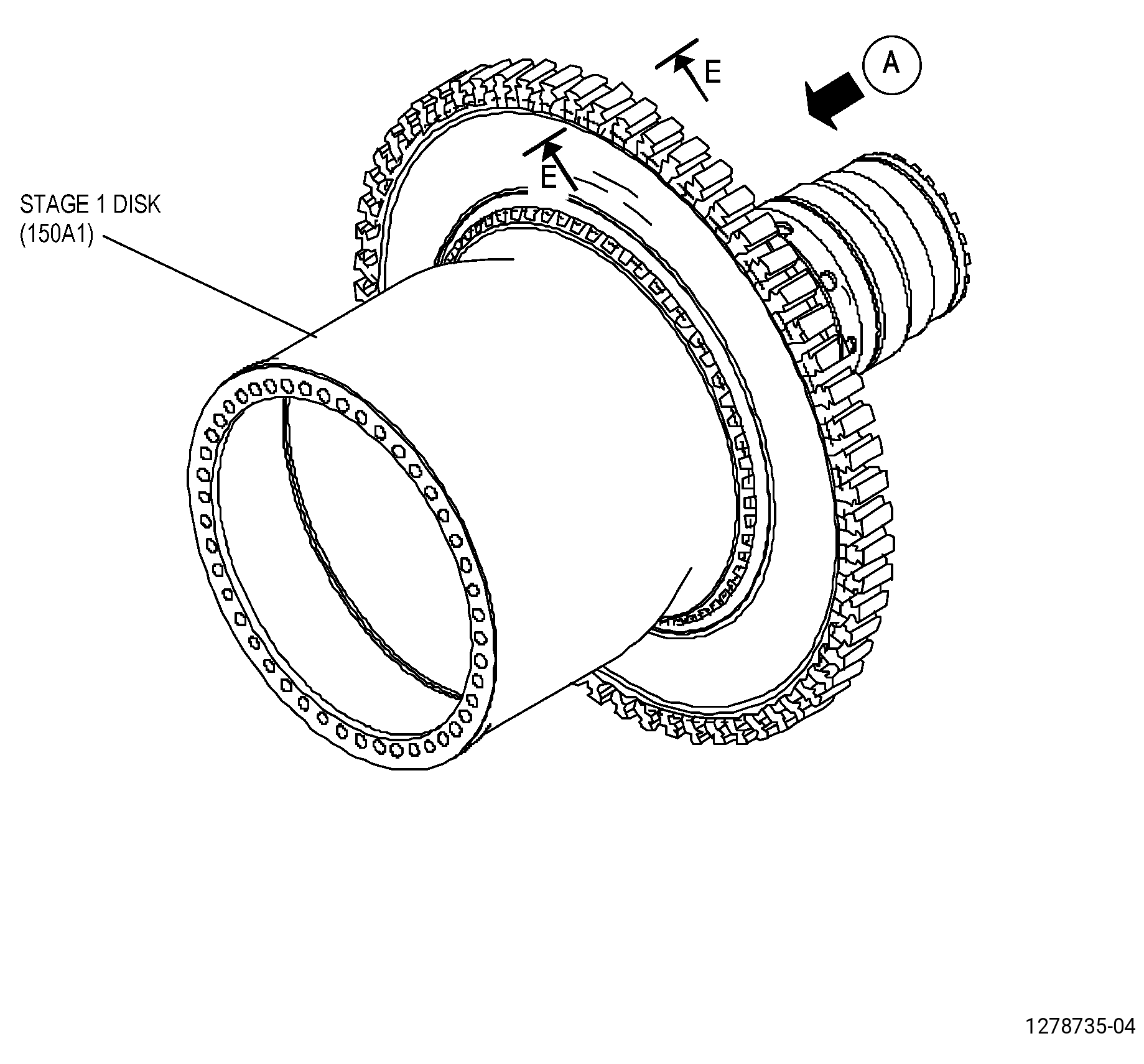
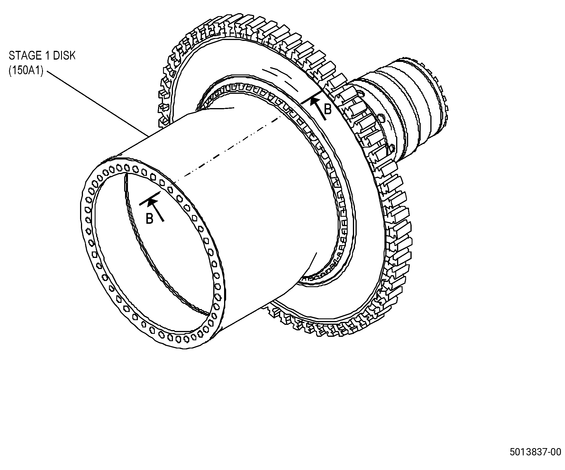
| A. | This procedure gives instructions to do an inspection of the HPT rotor stage 1 disk (stage 1 disk) (150A1). |
| B. | Carefully examine the areas that follow, because they are the most important. Refer to Figure 810, Figure 811, Figure 812, Figure 813, and Figure 814. |
| • |
|
| • |
|
| • |
|
| • |
|
| • |
|
| • |
|
| • |
|
| • |
|
| • |
|
| 2 . | Tools, Equipment, and Materials. |
| NOTE: |
|
| A. | Tools and Equipment. |
| (1) | Special Tools. None. |
| (2) | Standard Tools and Equipment. |
| (3) | Locally Manufactured Tools. None. |
| B. | Consumable Materials. |
|
| C. | Referenced Procedures. |
|
| D. | Expendable Parts. None. |
| 3 . | Specific Inspection Procedure. |
| NOTE: |
|
| Subtask 72-53-40-230-001 |
| A. | Do a fluorescent penetrant inspection of the stage 1 disk as follows: |
| Subtask 72-53-40-230-002 |
| (1) | Make sure that the stage 1 disk is clean. Refer to TASK 72-53-40-100-801 (72-53-40, Cleaning). |
| (2) | Do a Class G fluorescent penetrant inspection. Refer to TASK 70-32-02-230-001 (FLUORESCENT PENETRANT INSPECTION). |
| NOTE: |
|
| • |
|
| Subtask 72-53-40-250-003 |
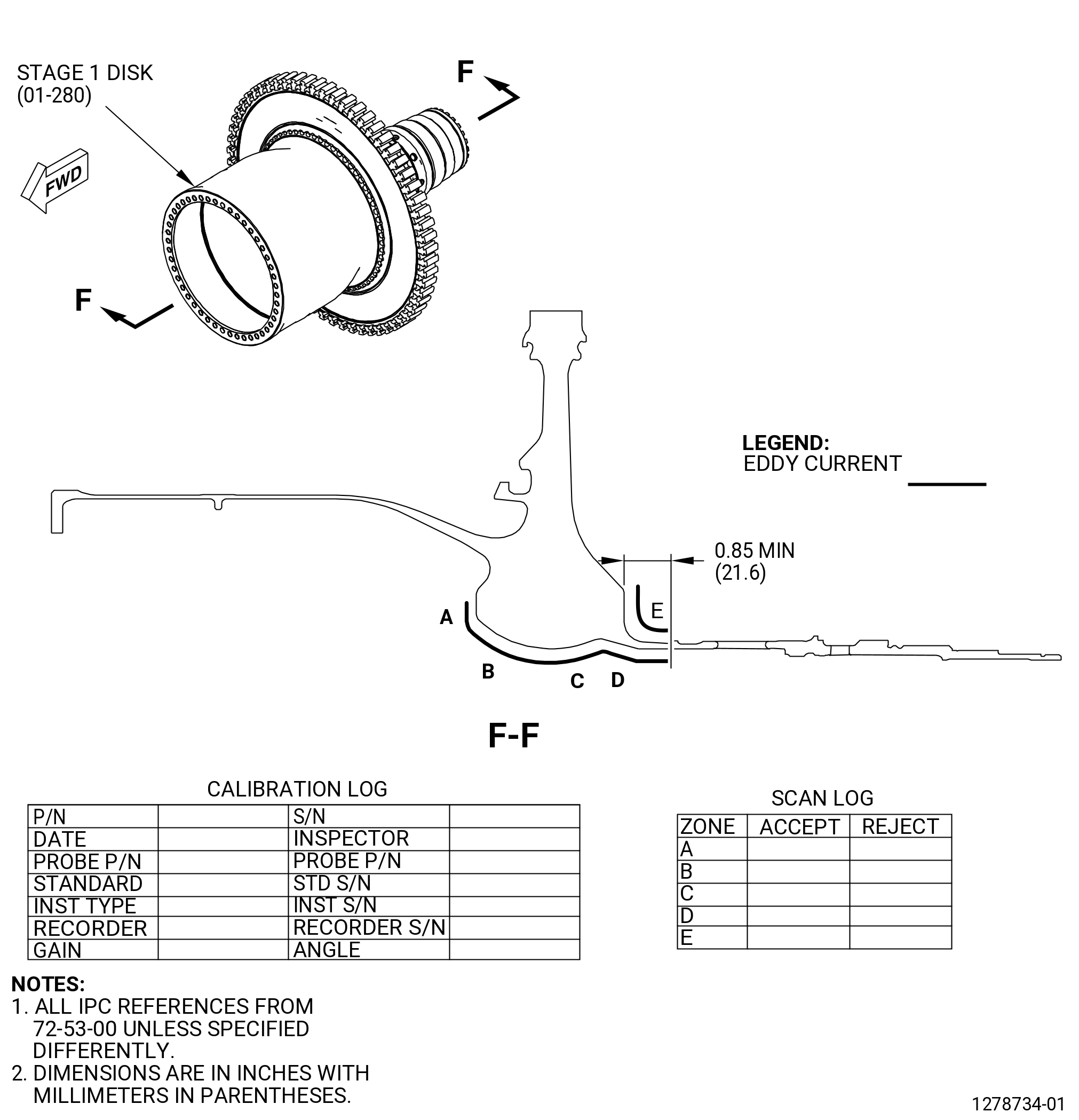
| B. | Do an eddy current inspection of bore surfaces. Refer to TASK 70-32-10-250-003 (2 MHZ EDDY CURRENT INSPECTION OF BORES IN ROTATING ENGINE HARDWARE USING SYSTEMS UNDER COMPUTER, NUMERIC, OR ROBOTIC CONTROL). |
| NOTE: |
|
| NOTE: |
|
| NOTE: |
|
| (1) | Inspect the bore areas shown in the scan plan. |
| (2) | Complete the eddy current data sheets. |
| Subtask 72-53-40-250-005 |
| (3) | Eddy current inspection evaluation limits. |
| (a) | The evaluation limit is 750 mV. |
| Subtask 72-53-40-250-006 |
| (4) | Eddy current inspection reject limits. |
| (a) | The reject limit is 750 mV after evaluation is complete. |
| Subtask 72-53-40-250-007 |
| (5) | All stage 1 disks that are rejected by the limits in Subtask 72-53-40-250-006 (paragraph 3.B.(4.)) are not serviceable. All stage 1 disks that are not rejected by the limits in Subtask 72-53-40-250-006 (paragraph 3.B.(4.)) are serviceable. |
| (6) | Make sure that all records that were made during the eddy current inspection are as complete as possible. Permanently keep these records for each stage 1 disk that was inspected. |
| Subtask 72-53-40-250-023 |
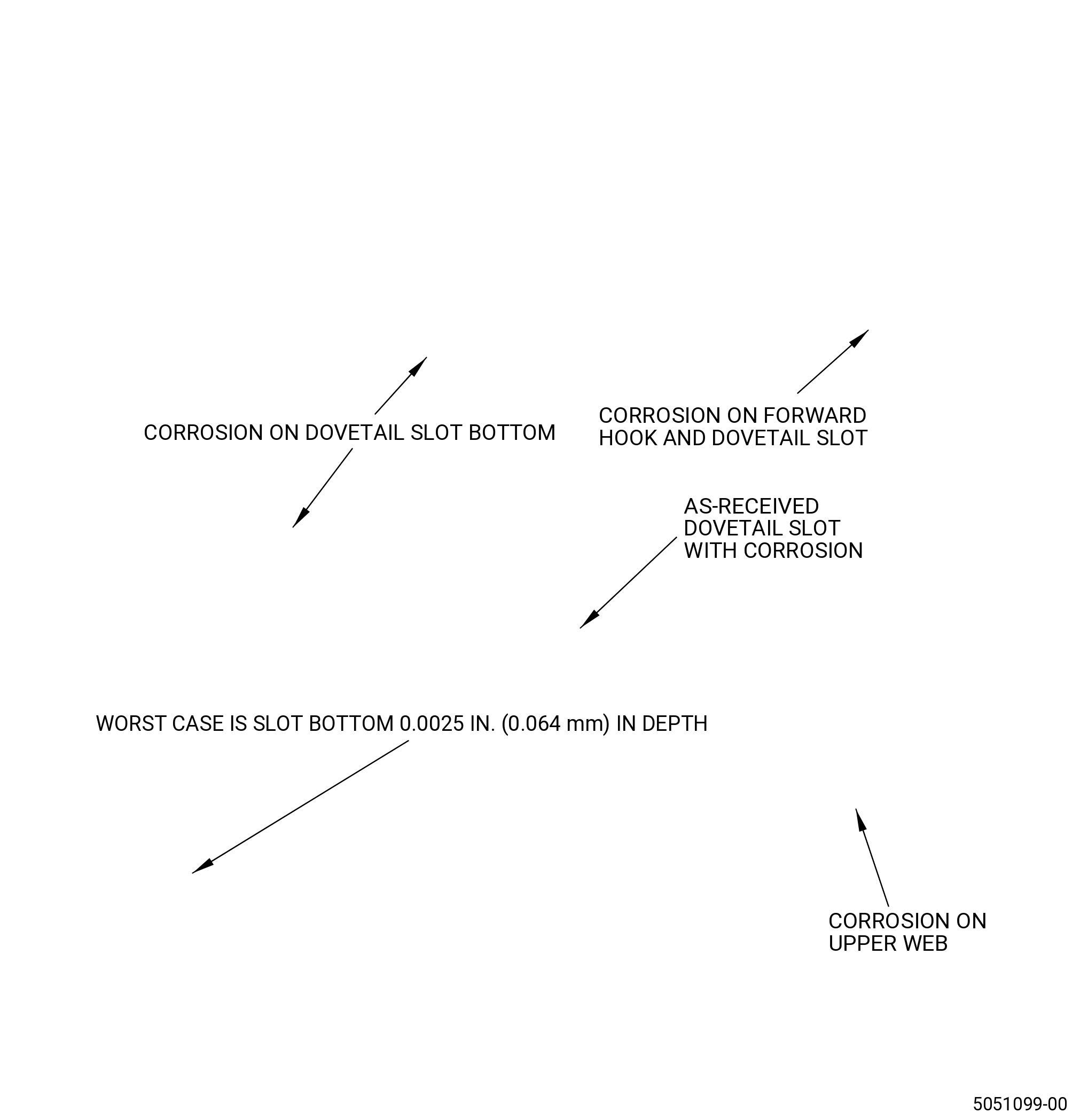
| C. | Do an eddy current inspection of the stage 1 disk dovetail slot bottoms as follows: |
| Subtask 72-53-40-250-008 |
| CAUTION: |
|
| (1) | Make sure the disk is clean. Refer to TASK 72-53-40-100-801 (72-53-40, Cleaning 001). |
| Subtask 72-53-40-250-009 |
| (2) | Do an eddy current inspection of the dovetail slot bottoms. Refer to TASK 70-32-23-250-801 (72-32-23, EDDY CURRENT INSPECTION OF DOVETAIL SLOT BOTTOMS IN ENGINE ROTATING HARDWARE USING AN AUTOMATED SYSTEM). |
| NOTE: |
|
| NOTE: |
|
| (3) | Use the GE-FQAP-584 Inspection Kit to do the inspection of the disk dovetail slot bottoms. |
| (4) | Examine the dovetail slot bottoms as shown in Figure 814. |
| Subtask 72-53-40-250-011 |
| (5) | Eddy current inspection evaluation limits. |
| (a) | The evaluation limit is three divisions above null point. |
| Subtask 72-53-40-250-012 |
| (6) | Eddy current inspection reject limits. |
| (a) | The rejection limit is three divisions above the null point after evaluation is complete. |
| Subtask 72-53-40-250-013 |
| (7) | All HPTR disks that are rejected by the limits in Subtask 72-53-40-250-012 (paragraph 3.C.(6)) are not serviceable. All disks that are not rejected by the limits in Subtask 72-53-40-250-011 (paragraph 3.C.(5)) are serviceable. |
| (8) | Complete the eddy current data sheets. |
| (9) | Make sure that all records that were made during the eddy current inspection are as complete as possible. Permanently keep these records for each HPTR disk that was inspected. |
| Subtask 72-53-40-270-001 |
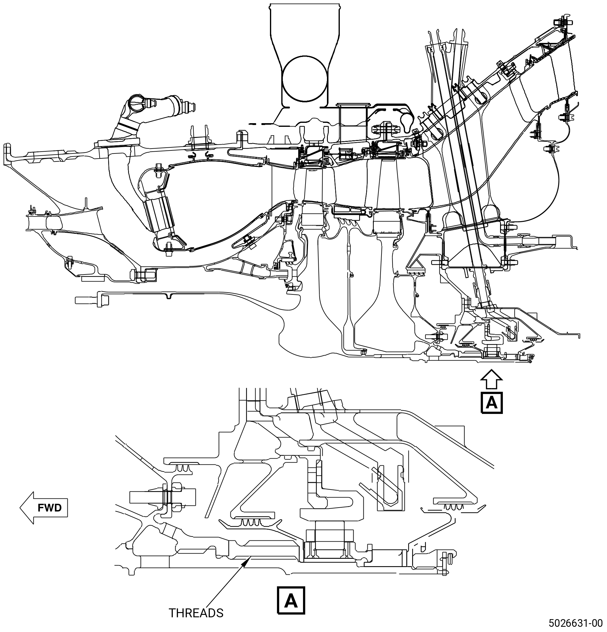
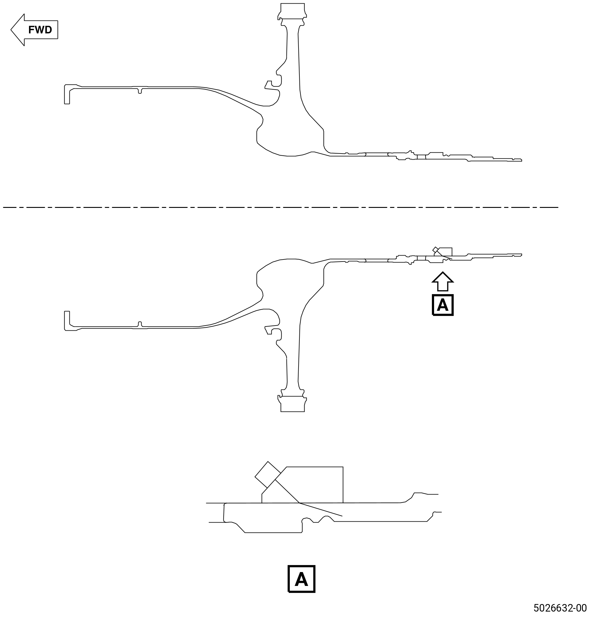
| D. | Do an ultrasonic inspection of the coupling nut threads of the stage 1 disk shaft. Refer to TASK 70-32-06-270-001 (ULTRASONIC INSPECTION) and as follows: |
| NOTE: |
|
| NOTE: |
|
| (1) | Applicable Documents: |
| (a) | NAS-410 (latest revision). |
| (b) | Applicable manufacturer’s equipment user’s manual. |
| (c) | FST Procedure 2286 - Kit Preparation and Quality Assurance Plan. |
| (2) | Personnel Requirements: |
| (a) | Personnel performing this inspection must be certified in accordance with NAS-410, or American Society of Nondestructive Testing (ASNT-TC-1A), or local certification process. |
| (b) | It is strongly recommended that personnel performing this inspection receive practical training in the use of this procedure and must demonstrate proficiency in the calibration, inspection and evaluation routines before accept/reject authority is delegated. |
| (c) | Any training that can be provided regarding the performance of this inspection does not imply that the personnel who receive that training have met the requirements for inspector certification in accordance with the appropriate certification document. |
| Subtask 72-53-40-820-001 |
| (3) | Initial Equipment Set-up: |
| NOTE: |
|
| (a) | Connect the ultrasonic instrument to the applicable power source and switch the instrument power to ON. Let the instrument warm up for at least 10 minutes or the manufacturer’s recommended warm up time. |
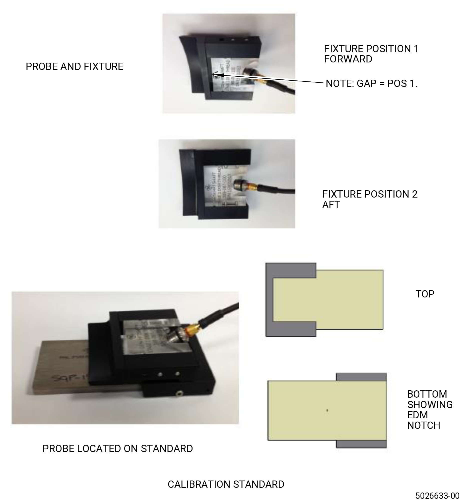
| (b) | Make sure that the transducer is correctly inserted into the scanning fixture and that the transducer and fixture are attached together. |
| (c) | Connect the probe to the instrument. |
| (d) | Set the transducer position to the forward position. |
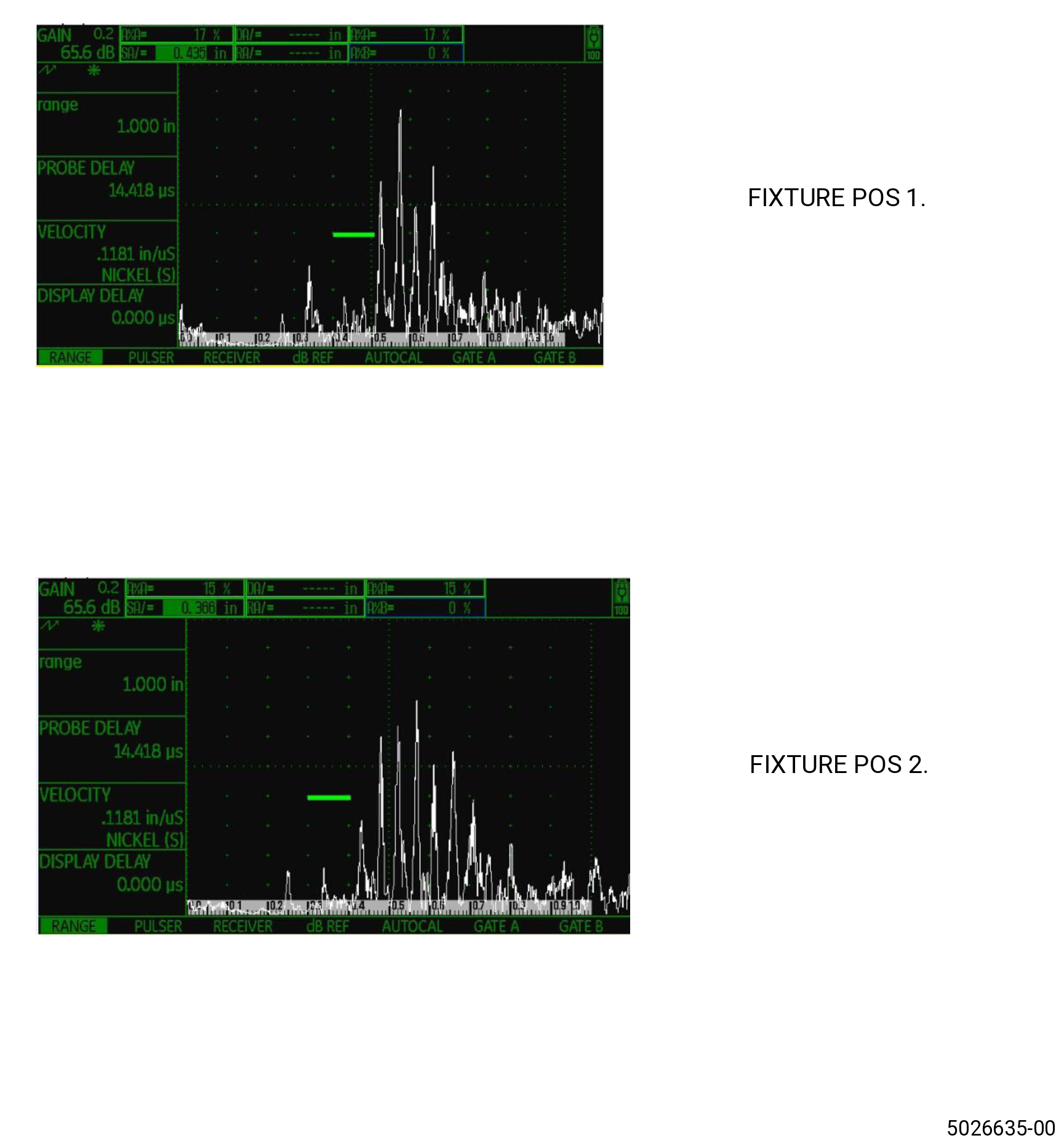
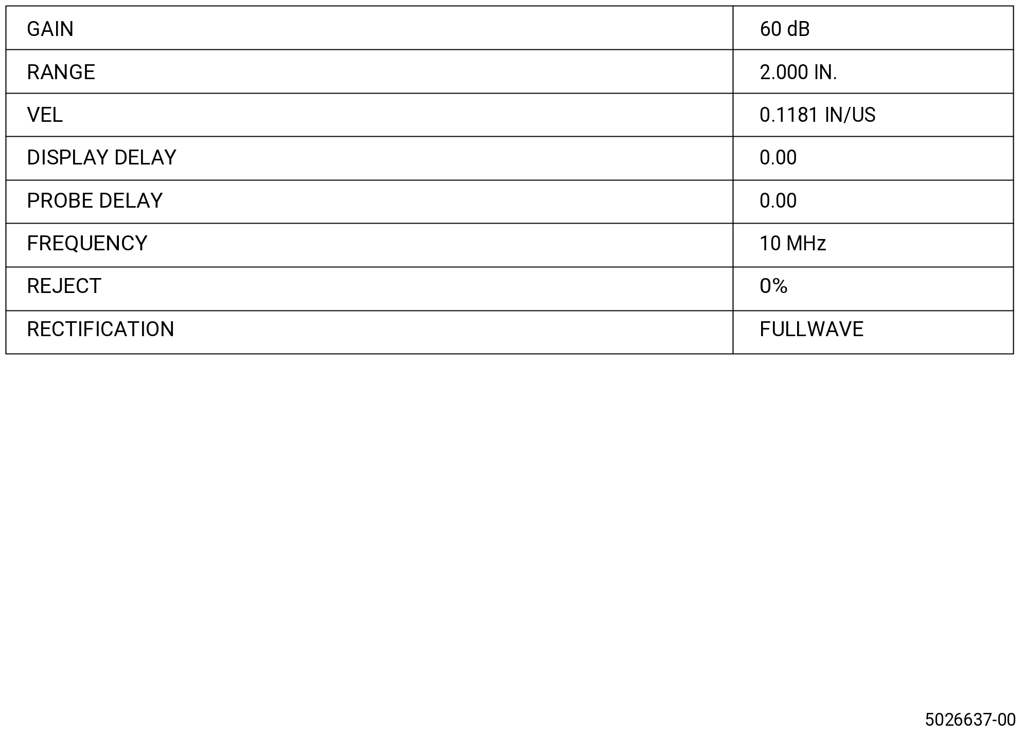
| (e) | Adjust the ultrasonic instrument to the basic settings. Refer to Figure 808. |
| Subtask 72-53-40-220-171 |
| (4) | Pre-Inspection Preparation: |
| (a) | Engines must be prepared for the inspection with the appropriate technical data to accomplish it as follows: |
| 1 | Make sure to get access to the inspection area. |
| Subtask 72-53-40-820-002 |
| (5) | Equipment Calibration: |
| (a) | Refer to Figure 804 and Figure 805. |
| (b) | Prepare the ultrasonic instrument and the probe. Refer to Subtask 72-53-40-820-001 (paragraph 3.D.(3)). |
| (c) | Apply couplant to the standard. |
| (d) | Position the probe on the standard with the sound pointed to the electro-discharge machined (EDM) notch. |
| (e) | Examine forward and backward to locate the response from the EDM notch. Maximize the response from the notch. |
| (f) | Adjust the gain to set the response from the EDM notch to 60 percent of full screen height (FSH). |
| (g) | Adjust the probe immediately only to set the response to 3.0 on the instrument baseline. |
| (h) | Adjust the range only to set the response from the EDM notch to 6.0 on the instrument baseline. |
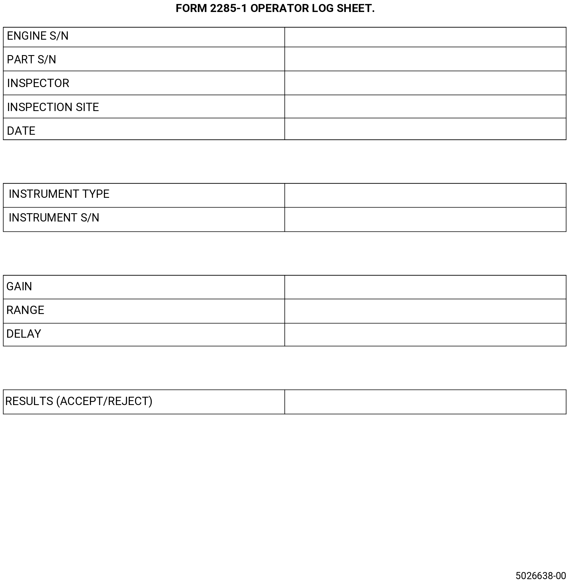
| (i) | Record the instrument settings on the Form 2285-1. Refer to Figure 809. |
| Subtask 72-53-40-270-002 |
| (6) | Inspection: |
| (a) | Make sure that the initial equipment set-up, the pre-inspection preparation and the system calibration are complete according to Subtask 72-53-40-820-001 (paragraph 3.D.(3)) thru Subtask 72-53-40-820-002 (paragraph 3.D.(5)). |
| (b) | Set a gate from the 4th primary division to the 5th primary division on the instrument baseline at a level of 40 percent FSH. Refer to Figure 806. |
| (c) | Apply couplant to the inspection area. |
| (d) | Make sure that the probe position is at the forward number 1 position. Refer to Figure 804. |
| (e) | Put the fixture on the inspection area touching against the radius. Refer to Figure 807. |
| (f) | Examine in a circumferential direction making sure that the fixture is touching against the radius. |
| (g) | Monitor the instrument for indications in the gate which are more than 40 percent of FSH. |
| (h) | Examine repeatable indications which are equal to or more than 40 percent of FSH. Refer to Subtask 72-53-40-270-003 (paragraph 3.D.(8)). |
| (i) | Set a gate from the 3rd primary division to the 4th primary division on the instrument baseline at a level of 40 percent FSH. Refer to Figure 806. |
| (j) | Adjust the probe position to number 2 - aft. Refer to Figure 804. |
| (k) | Apply couplant to the inspection area. |
| (l) | Put the fixture on the inspection area touching up to the radius. Refer to Figure 807. |
| (m) | Examine in a circumferential direction to make sure that the fixture is touching against the radius. |
| (n) | Monitor the instrument for indications in the gate which are more than 40 percent of FSH. |
| (o) | Examine repeatable indications which are equal to or more than 40 percent FSH. Refer to Subtask 72-53-40-270-003 (paragraph 3.D.(8)). |
| Subtask 72-53-40-820-003 |
| (7) | Calibration Check: |
| (a) | A calibration check must be performed after inspection. Also, check calibration whenever any system component or operator is changed, after any loss of power and at any time the operator suspects a change in the system. |
| (b) | If the amplitude of the response from the EDM notch has increased by more than 10 percent FSH above the calibration amplitude, the system must be re-calibrated before the inspection of additional hardware. It will be necessary to re-inspect any rejected hardware examined since the last acceptable calibration once correct calibration has been achieved. |
| (c) | If the amplitude of the response from the EDM notch has decreased by more than 10 percent FSH below the calibration amplitude, the system must be re-calibrated and all hardware inspected since the last acceptable calibration or calibration check must be re-inspected. |
| Subtask 72-53-40-270-003 |
| (8) | Indication Evaluation: |
| (a) | Any indication(s) that equals or exceeds 40 percent FSH must be evaluated as follows: |
| 1 | Verify that the calibration is acceptable. Refer to Subtask 72-53-40-820-003 (paragraph 3.D.(7)). |
| 2 | Repeat the inspection. |
| 3 | If the indication repeats itself and is above 60 percent, the part is rejectable. |
| 4 | Record the results on the Form 2285-1. Refer to Figure 809. |
| Subtask 72-53-40-270-004 |
| (9) | Documentation: |
| (a) | All calibration and inspection data must be recorded on the Form 2285-1. Refer to Figure 809. |
| Subtask 72-53-40-220-205 |
| E. | Do the special procedure as follows: |
| (1) | Focused inspection of the forward middle radial rabbet for dents. Refer to TASK 72-53-40-800-802 (72-53-40, SPECIAL PROCEDURES 001). |
| Subtask 72-53-40-270-010 |
| F. | Do an immersion ultrasonic inspection of the stage 1 disk. Refer to TASK 72-53-40-800-803 (72-53-40, SPECIAL PROCEDURES 002). |
| 4 . | Visual Inspection. |
| The information that follows is applicable to all procedural steps for the visual inspection of the stage 1 disk surfaces: |
| • |
|
| • |
|
| • |
|
| Subtask 72-53-40-220-004 |
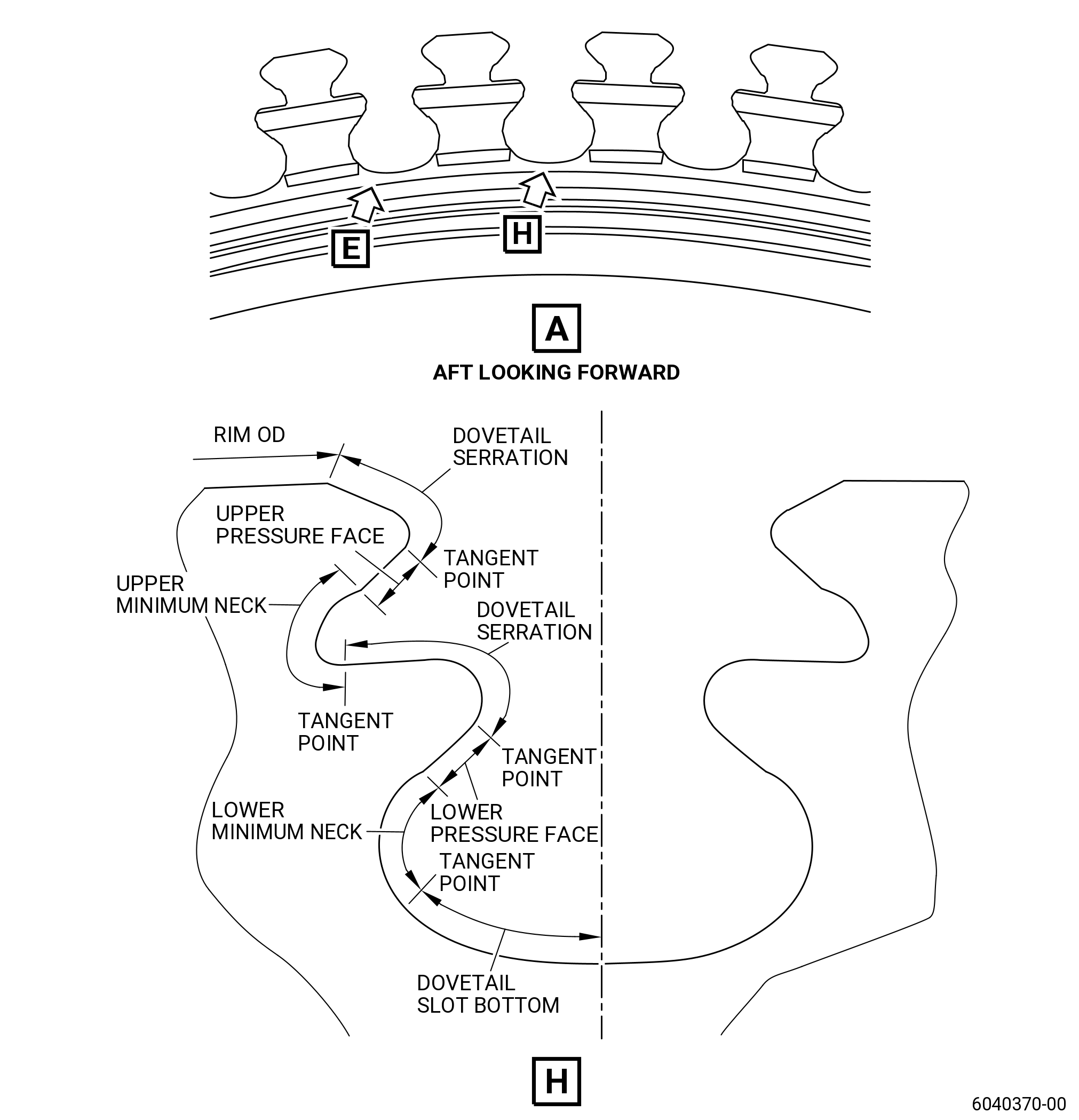
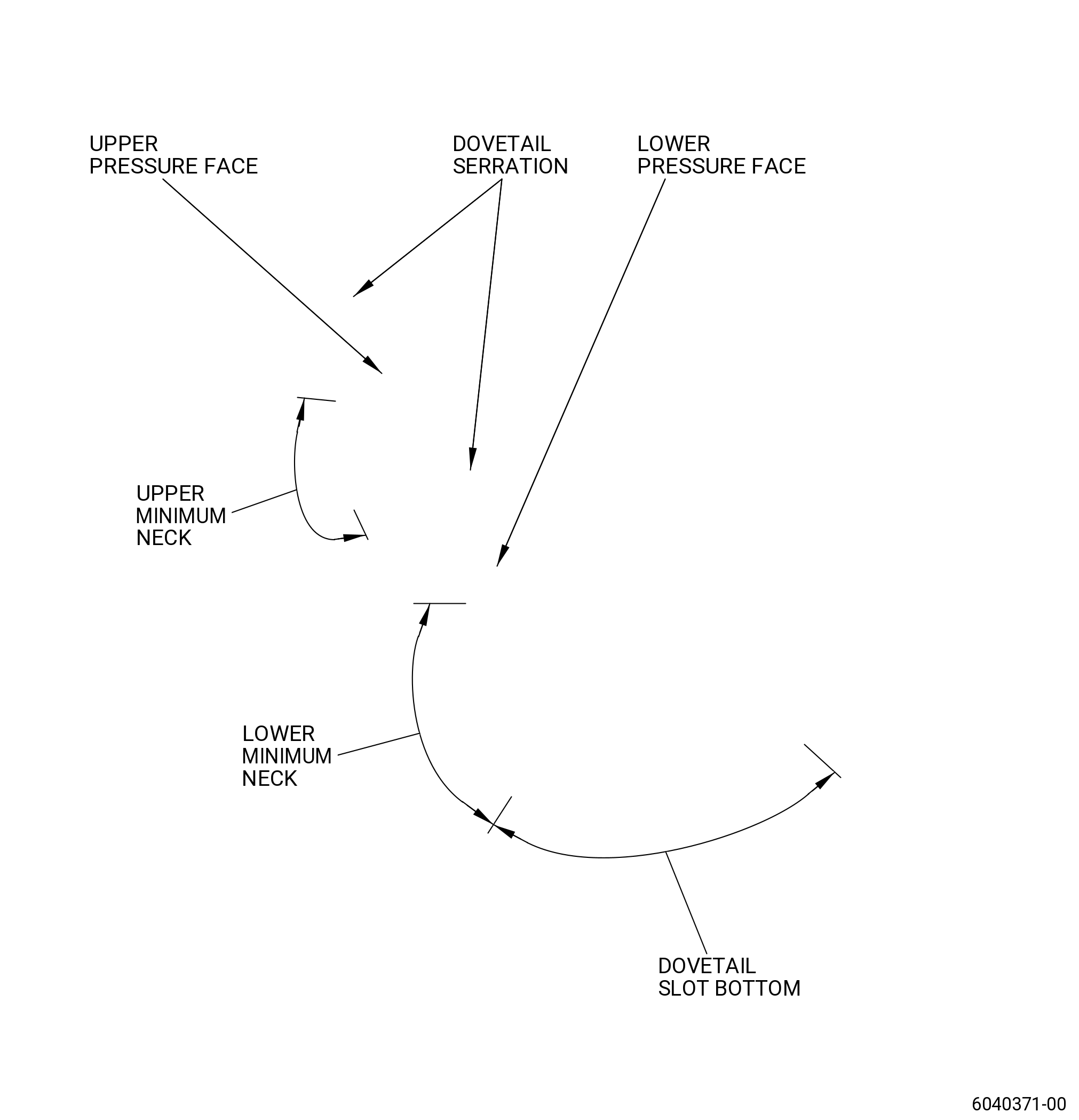
| A. | Do an inspection of the dovetail serrations. Refer to Figure 810 and as follows: |
| (1) | Nicks and dents: |
| Maximum serviceable limit: |
|
| Repair method: |
|
| Subtask 72-53-40-220-005 |
| (2) | Scratches: |
| Maximum serviceable limit: |
|
| Repair method: |
|
| Subtask 72-53-40-220-006 |
| (3) | Pitting related to corrosion: |
| Maximum serviceable limit: |
|
| Repair method: |
|
| Subtask 72-53-40-220-007 |
| B. | Do an inspection of the dovetail pressure faces as follows. Refer to Figure 810. |
| (1) | Nicks and dents: |
| Maximum serviceable limit: |
|
|
| Repair method: |
|
| Subtask 72-53-40-220-008 |
| (2) | Wear, fretting, or galling: |
| Maximum serviceable limit: |
|
| Repair method: |
|
| Subtask 72-53-40-220-009 |
| (3) | Radial scratches: |
| Maximum serviceable limit: |
|
| Repair method: |
|
| Subtask 72-53-40-220-010 |
| (4) | Axial scratches: |
| Maximum serviceable limit: |
|
| Repair method: |
|
| Subtask 72-53-40-220-011 |
| (5) | Pitting related to corrosion: |
| Maximum serviceable limit: |
|
| Repair method: |
|
| Subtask 72-53-40-220-012 |
| C. | Do an inspection of the dovetail upper minimum neck radii. Refer to Figure 810 and as follows: |
| (1) | Nicks and dents: |
| Maximum serviceable limit: |
|
| Repair method: |
|
| Subtask 72-53-40-220-013 |
| (2) | Scratches: |
| Maximum serviceable limit: |
|
| Repair method: |
|
| Subtask 72-53-40-220-014 |
| (3) | Pitting related to corrosion: |
| Maximum serviceable limit: |
|
| Repair method: |
|
| Subtask 72-53-40-220-015 |
| D. | Do an inspection of the dovetail slot bottoms and lower minimum neck radii. Refer to Figure 810 and as follows: |
| (1) | Nicks and dents: |
| Maximum serviceable limit: |
|
| Repair method: |
|
| Subtask 72-53-40-220-016 |
| (2) | Scratches: |
| Maximum serviceable limit: |
|
| Repair method: |
|
| Subtask 72-53-40-220-017 |
| (3) | Pitting related to corrosion in the slot bottom: |
| Maximum serviceable limit: |
|
| Repair method: |
|
| Subtask 72-53-40-220-191 |
| (4) | Pitting related to corrosion in the lower minimum neck radii: |
| Maximum serviceable limit: |
|
| Repair method: |
|
| Subtask 72-53-40-220-018 |
| E. | Do an inspection of the rim OD and end faces as follows. Refer to Figure 810. |
| (1) | Nicks: |
| Maximum serviceable limit: |
|
| Repair method: |
|
| Subtask 72-53-40-220-019 |
| (2) | Dents: |
| Maximum serviceable limit: |
|
| Repair method: |
|
| Subtask 72-53-40-220-020 |
| (3) | Scratches: |
| Maximum serviceable limit: |
|
| Repair method: |
|
| Subtask 72-53-40-220-021 |
| (4) | Galling and fretting on forward end face: |
| Maximum serviceable limit: |
|
| Repair method: |
|
| Subtask 72-53-40-220-198 |
| (5) | Galling and fretting on aft end face: |
| Maximum serviceable limit: |
|
| Repair method: |
|
| Subtask 72-53-40-220-022 |
| (6) | Pitting related to corrosion: |
| Maximum serviceable limit: |
|
| Repair method: |
|
| Subtask 72-53-40-220-023 |
| F. | Do an inspection of the web and hub faces as follows. Refer to Figure 810. |
| NOTE: |
|
| (1) | Nicks and scratches (forward upper web, forward lower web, and forward hub faces): |
| Maximum serviceable limit: |
|
| Repair method: |
|
| Subtask 72-53-40-220-024 |
| (2) | Nicks and scratches (for all other areas): |
| Maximum serviceable limit: |
|
| Repair method: |
|
| Subtask 72-53-40-220-025 |
| (3) | Dents (forward upper web, forward lower web, and forward hub faces): |
| Maximum serviceable limit: |
|
| Repair method: |
|
| Subtask 72-53-40-220-148 |
| (4) | Dents (for all other areas): |
| Maximum serviceable limit: |
|
| Repair method: |
|
| Subtask 72-53-40-220-149 |
| (5) | Fretting: |
| Maximum serviceable limit: |
|
| Repair method: |
|
| Subtask 72-53-40-220-165 |
| (6) | Pitting on the forward upper web related to corrosion: |
| Maximum serviceable limit: |
|
| Repair method: |
|
| Subtask 72-53-40-220-254 |
| (7) | Pitting on the aft upper/lower web related to corrosion: |
| Maximum serviceable limit: |
|
| Repair method: |
|
| Subtask 72-53-40-220-026 |
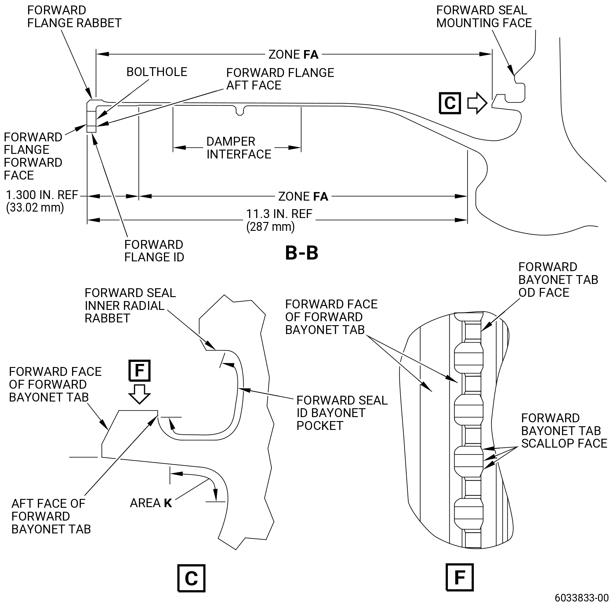
| G. | Do an inspection of the forward flange forward face and forward flange ID. Refer to Figure 811 and as follows: |
| (1) | Fretting: |
| Maximum serviceable limit: |
|
| Repair method: |
|
| Subtask 72-53-40-220-027 |
| (2) | Nicks, dents, and scratches on the forward flange forward face: |
| Maximum serviceable limit: |
|
| Repair method: |
|
| Subtask 72-53-40-220-196 |
| (3) | Deleted. |
| Subtask 72-53-40-220-028 |
| H. | Do an inspection of the stage 2 disk pilot arm interface. Refer to Figure 812 and as follows: |
| (1) | Fretting: |
| Maximum serviceable limit: |
|
| Repair method: |
|
| Subtask 72-53-40-220-029 |
| (2) | Deleted: |
| Maximum serviceable limit: |
|
| Repair method: |
|
| Subtask 72-53-40-220-150 |
| (3) | Nicks, dents, and scratches: |
| Maximum serviceable limit: |
|
| Repair method: |
|
| Subtask 72-53-40-220-166 |
| (4) | Deleted. |
| Maximum serviceable limit: |
|
| Repair method: |
|
| Subtask 72-53-40-220-072 |
| I. | Do an inspection of the forward seal mounting face as follows. Refer to Figure 811 for: |
| (1) | Galling, wear, or fretting: |
| Maximum serviceable limit: |
|
| Repair method: |
|
| Subtask 72-53-40-220-151 |
| (2) | Nicks, dents, and scratches: |
| Maximum serviceable limit: |
|
| Repair method: |
|
| Subtask 72-53-40-220-182 |
| (3) | Pitting related to corrosion: |
| Maximum serviceable limit: |
|
| Repair method: |
|
| Subtask 72-53-40-220-067 |
| J. | Do an inspection of the mounting face of the sump seal pilot. Refer to Figure 812 and as follows: |
| (1) | Fretting/pitting: |
| Maximum serviceable limit: |
|
| Repair method: |
|
| Subtask 72-53-40-220-068 |
| (2) | Nicks and scratches: |
| Maximum serviceable limit: |
|
| Repair method: |
|
| Subtask 72-53-40-220-069 |
| (3) | Dents: |
| Maximum serviceable limit: |
|
| Repair method: |
|
| Subtask 72-53-40-220-030 |
| K. | Do an inspection of the disk bore as follows. Refer to Figure 810. |
| (1) | Nicks and scratches: |
| Maximum serviceable limit: |
|
| Repair method: |
|
| Subtask 72-53-40-220-031 |
| (2) | Dents: |
| Maximum serviceable limit: |
|
| Repair method: |
|
| Subtask 72-53-40-220-032 |
| (3) | Damage in the edge radius: |
| Maximum serviceable limit: |
|
| Repair method: |
|
| Subtask 72-53-40-220-033 |
| L. | Do an inspection of damper interface on the ID of forward shaft. Refer to Figure 811 and as follows: |
| (1) | Fretting or wear: |
| Maximum serviceable limit: |
|
| Repair method: |
|
| Subtask 72-53-40-220-152 |
| (2) | Nicks, dents, and scratches: |
| Maximum serviceable limit: |
|
| Repair method: |
|
| Subtask 72-53-40-220-077 |
| (3) | Deleted. |
| Subtask 72-53-40-220-192 |
| (4) | Deleted. |
| Maximum serviceable limit: |
|
| Repair method: |
|
| Subtask 72-53-40-220-034 |
| M. | Do an inspection of the boltholes on the forward shaft as follows. Refer to Figure 811. |
| (1) | Fretting: |
| Maximum serviceable limit: |
|
| Repair method: |
|
| Subtask 72-53-40-220-035 |
| (2) | Damage in the edge radius: |
| Maximum serviceable limit: |
|
| Repair method: |
|
| Subtask 72-53-40-220-036 |
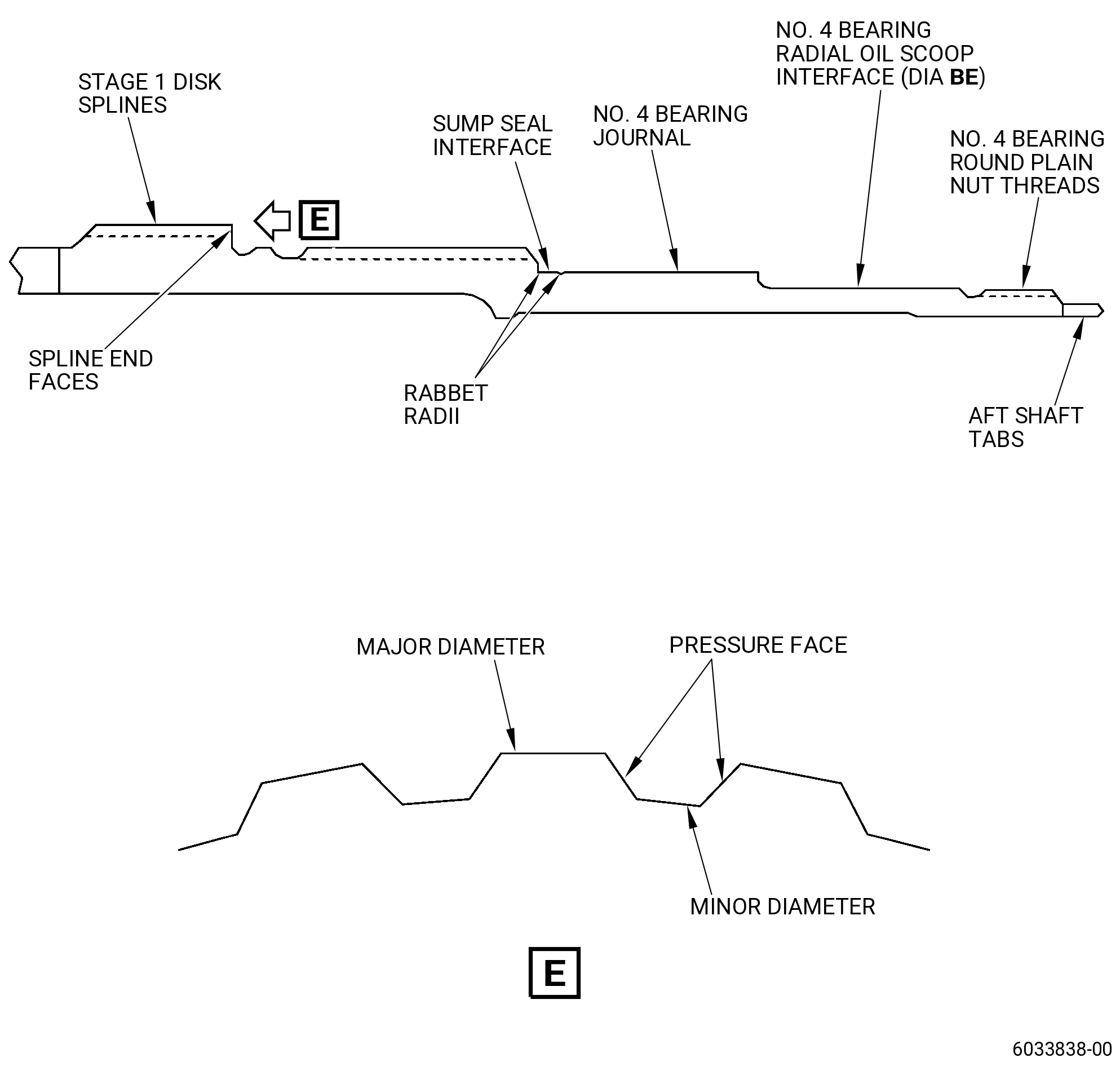
| N. | Do an inspection of the spline surfaces on the aft shaft as follows. Refer to Figure 812. |
| (1) | Nicks or dents on the end faces: |
| Maximum serviceable limit: |
|
| Repair method: |
|
| Subtask 72-53-40-220-153 |
| (2) | Pickup, high metal, or burrs on all other surfaces: |
| Maximum serviceable limit: |
|
| Repair method: |
|
| Subtask 72-53-40-220-037 |
| (3) | Wear or galling on all other surfaces: |
| Maximum serviceable limit: |
|
| Repair method: |
|
| Subtask 72-53-40-220-038 |
| (4) | Nicks, dents, and scratches on major diameter and pressure faces (except root fillets): |
| Maximum serviceable limit: |
|
| Repair method: |
|
| Subtask 72-53-40-220-039 |
| (5) | Nicks, dents, and scratches on minor diameter and root fillets: |
| Maximum serviceable limit: |
|
| Repair method: |
|
| Subtask 72-53-40-220-042 |
| O. | Do an inspection of the air duct rabbet/mate face on the aft shaft as follows. Refer to Figure 812 |
| (1) | Fretting: |
| Maximum serviceable limit: |
|
| Maximum repairable limit: |
|
| Repair method: |
|
| NOTE: |
|
| Subtask 72-53-40-220-043 |
| (2) | Nicks, dents, and scratches: |
| Maximum serviceable limit: |
|
| Repair method: |
|
| Subtask 72-53-40-220-044 |
| P. | Do an inspection of the internal and external surfaces in zone FA (critical) on the forward shaft as follows. Refer to Figure 811. |
| (1) | Nicks, dents, and scratches: |
| Maximum serviceable limit: |
|
| Repair method: |
|
| Subtask 72-53-40-220-045 |
| Q. | Do an inspection of the internal and external surfaces in zone FB (excluding mounting face of the sump seal pilot) on the aft shaft as follows. Refer to Figure 812. |
| (1) | Nicks and scratches: |
| Maximum serviceable limit: |
|
| Repair method: |
|
| Subtask 72-53-40-220-046 |
| (2) | Dents: |
| Maximum serviceable limit: |
|
| Repair method: |
|
| Subtask 72-53-40-220-047 |
| R. | Do an inspection of the heat shield pilots as follows. Refer to Figure 812. |
| (1) | Pickup and high metal: |
| Maximum serviceable limit: |
|
| Repair method: |
|
| Subtask 72-53-40-220-048 |
| (2) | Nicks, dents, and scratches: |
| Maximum serviceable limit: |
|
| Repair method: |
|
| Subtask 72-53-40-220-049 |
| S. | Do an inspection of the forward flange rabbet as follows. Refer to Figure 811. |
| (1) | Fretting/wear: |
| Maximum serviceable limit: |
|
| Repair method: |
|
| Subtask 72-53-40-220-050 |
| T. | Do an inspection of the No. 4 bearing journal surface on the aft shaft as follows. Refer to Figure 812. |
| (1) | Pickup and high metal: |
| Maximum serviceable limit: |
|
| Repair method: |
|
| Subtask 72-53-40-220-051 |
| (2) | Nicks and dents: |
| Maximum serviceable limit: |
|
| Repair method: |
|
| Subtask 72-53-40-220-212 |
| (3) | Scores and scratches: |
| Maximum serviceable limit: |
|
| Repair method: |
|
| Subtask 72-53-40-220-052 |
| (4) | Fretting: |
| Maximum serviceable limit: |
|
| Repair method: |
|
| Subtask 72-53-40-220-053 |
| U. | Do an inspection of the air duct threads on the aft shaft. Refer to Figure 812 and as follows: |
| (1) | Nicks, dents, pickup, or high metal: |
| Maximum serviceable limit: |
|
| Repair method: |
|
| Subtask 72-53-40-220-054 |
| (2) | Pitting: |
| Maximum serviceable limit: |
|
| Repair method: |
|
| Subtask 72-53-40-220-055 |
| V. | Do an inspection of the No. 4 bearing radial oil scoop diameter (diameter BE) on the aft shaft as follows. Refer to Figure 812. |
| (1) | Nicks and dents: |
| Maximum serviceable limit: |
|
| Repair method: |
|
| Subtask 72-53-40-220-213 |
| (2) | Scores and scratches: |
| Maximum serviceable limit: |
|
| Repair method: |
|
| Subtask 72-53-40-220-154 |
| (3) | Wear, galling, fretting, or rubbing: |
| Maximum serviceable limit: |
|
| Repair method: |
|
| Subtask 72-53-40-220-056 |
| W. | Do an inspection of all areas of the stage 1 disk for: |
| (1) | Discoloration: |
| Maximum serviceable limit: |
|
| Repair method: |
|
| Subtask 72-53-40-220-076 |
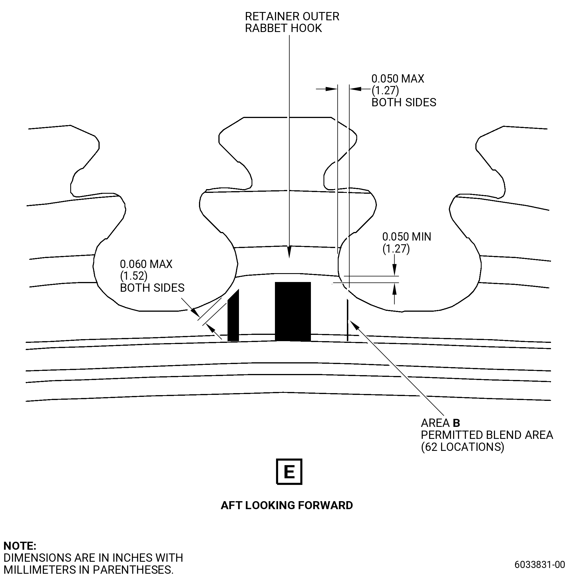
| X. | Do an inspection of the disk post aft face below the retainer outer rabbet hook (area B and area K). Refer to Figure 810, Figure 811, and as follows: |
| (1) | Nicks, dents, and scratches in area B. |
| Maximum serviceable limit: |
|
| Repair method: |
|
| Subtask 72-53-40-220-255 |
| (2) | Nicks, dents, and scratches in area K: |
| Maximum serviceable limit: |
|
| Repair method: |
|
| Subtask 72-53-40-220-155 |
| Y. | Do an inspection of the interstage seal disk ID bayonet as follows. Refer to Figure 812. |
| (1) | Fretting: |
| Maximum serviceable limit: |
|
| Repair method: |
|
| Subtask 72-53-40-220-156 |
| (2) | Nicks, dents, and scratches: |
| Maximum serviceable limit: |
|
| Repair method: |
|
| Subtask 72-53-40-220-222 |
| (3) | Wear on tab mounting faces of the interstage seal bayonet: |
| Maximum serviceable limit: |
|
| Repair method: |
|
| Subtask 72-53-40-220-223 |
| (4) | Wear on the sides of bayonets: |
| Maximum serviceable limit: |
|
| Repair method: |
|
| Subtask 72-53-40-220-256 |
| (5) | Nicks, dents, scratches, and wear on the corner of the bayonet tabs: |
| Maximum serviceable limit: |
|
| Repair method: |
|
| Subtask 72-53-40-220-224 |
| Z. | Do an inspection of the aft shaft tabs. Refer to Figure 812 and as follows: |
| (1) | Fretting and wear: |
| Maximum serviceable limit: |
|
| Repair method: |
|
| Subtask 72-53-40-220-225 |
| (2) | Nicks, dents, and scratches: |
| Maximum serviceable limit: |
|
| Repair method: |
|
| Subtask 72-53-40-220-157 |
| AA. | Do an inspection of the forward seal ID bayonet pocket. Refer to Figure 811 and as follows: |
| (1) | Nicks, dents, and scratches: |
| Maximum serviceable limit: |
|
| Repair method: |
|
| Subtask 72-53-40-220-158 |
| (2) | Pitting related to corrosion: |
| Maximum serviceable limit: |
|
| Repair method: |
|
| Subtask 72-53-40-220-159 |
| (3) | Deleted. |
| Maximum serviceable limit: |
|
| Repair method: |
|
| Subtask 72-53-40-220-183 |
| (4) | Deleted. |
| Maximum serviceable limit: |
|
| Repair method: |
|
| Subtask 72-53-40-220-184 |
| (5) | Deleted. |
| Maximum serviceable limit: |
|
| Repair method: |
|
| Subtask 72-53-40-220-160 |
| AB. | Do an inspection of the forward middle radial rabbet. Refer to Figure 810 and as follows: |
| (1) | Fretting and wear footprint on forward middle radial rabbet (caused by contact from the HPT Forward Seal Diameter F): |
| Maximum serviceable limit: |
|
| Maximum repairable limit: |
|
| Repair method: |
|
| • |
|
| • |
|
| • |
|
| • |
|
| NOTE: |
|
| Subtask 72-53-40-220-161 |
| (2) | Deleted. |
| Maximum serviceable limit: |
|
| Repair method: |
|
| Subtask 72-53-40-220-206 |
| (3) | Nicks and dents located on the forward middle radial rabbet (including the adjacent chamfer): |
| Maximum serviceable limit: |
|
| Maximum repairable limit: |
|
| • |
|
| • |
|
| Repair method: |
|
| Subtask 72-53-40-220-235 |
| (4) | Deleted. |
| Maximum serviceable limit: |
|
| Repair method: |
|
| Subtask 72-53-40-220-207 |
| (5) | Deleted. |
| Maximum serviceable limit: |
|
| Repair method: |
|
| Subtask 72-53-40-220-167 |
| (6) | Pitting related to corrosion: |
| Maximum serviceable limit: |
|
| Repair method: |
|
| Subtask 72-53-40-220-208 |
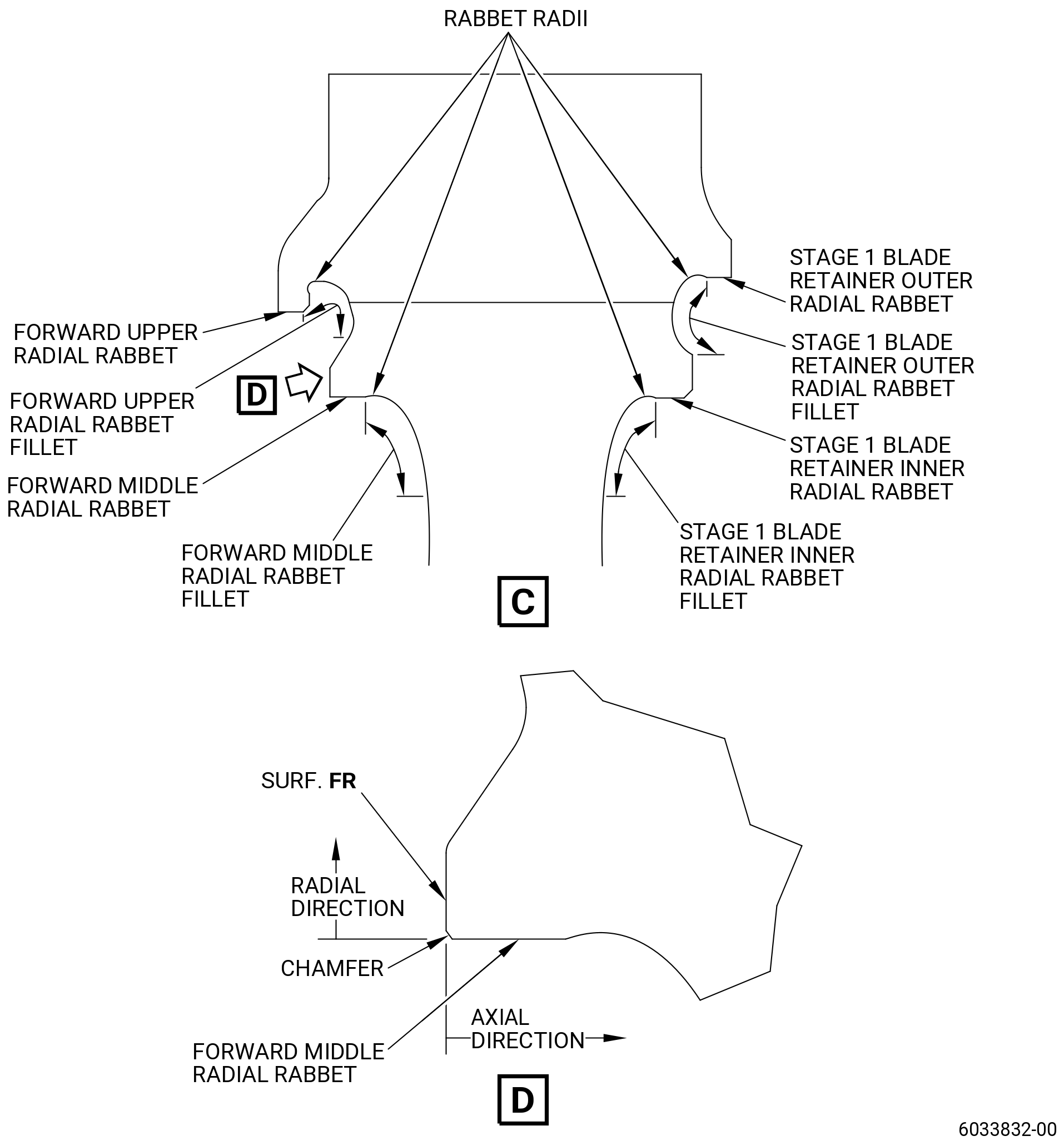
| AC. | Do an inspection of the axial face adjacent to the forward middle radial rabbet (surface FR) as follows: |
| (1) | Do a x10 white light focused inspection of the axial face for bulging or plastic deformation: |
| Maximum serviceable limit: |
|
| Repair method: |
|
| Subtask 72-53-40-220-257 |
| AD. | Do an inspection of stage 2 disk flange rabbet/mate face for: |
| (1) | Wear, fretting, or galling: |
| Maximum serviceable limit: |
|
| Repair method: |
|
| Subtask 72-53-40-220-258 |
| (2) | Nicks, dents, and scratches: |
| Maximum serviceable limit: |
|
| Repair method: |
|
| Subtask 72-53-40-220-259 |
| (3) | Pitting: |
| Maximum serviceable limit: |
|
| Repair method: |
|
| Subtask 72-53-40-220-260 |
| AE. | Do an inspection of the forward upper radial rabbet surface. Refer to Figure 810 and as follows: |
| (1) | Fretting: |
| Maximum serviceable limit: |
|
| Repair method: |
|
| Subtask 72-53-40-220-261 |
| (2) | Nicks and dents: |
| Maximum serviceable limit: |
|
| Repair method: |
|
| Subtask 72-53-40-220-262 |
| (3) | Pitting related to corrosion: |
| Maximum serviceable limit: |
|
| Repair method: |
|
| Subtask 72-53-40-220-263 |
| AF. | Do an inspection of the forward seal inner radial rabbet surface. Refer to Figure 811 and as follows: |
| (1) | Fretting: |
| Maximum serviceable limit: |
|
| Repair method: |
|
| Subtask 72-53-40-220-264 |
| (2) | Nicks and dents: |
| Maximum serviceable limit: |
|
| Repair method: |
|
| Subtask 72-53-40-220-265 |
| (3) | Pitting related to corrosion: |
| Maximum serviceable limit: |
|
| Repair method: |
|
| Subtask 72-53-40-220-266 |
| AG. | Do an inspection of the stage 1 blade retainer outer radial rabbet surface. Refer to Figure 810 and as follows: |
| (1) | Fretting: |
| Maximum serviceable limit: |
|
| Repair method: |
|
| Subtask 72-53-40-220-267 |
| (2) | Nicks and dents: |
| Maximum serviceable limit: |
|
| Repair method: |
|
| Subtask 72-53-40-220-268 |
| (3) | Pitting related to corrosion: |
| Maximum serviceable limit: |
|
| Repair method: |
|
| Subtask 72-53-40-220-269 |
| AH. | Do an inspection of the stage 1 blade retainer inner radial rabbet surface. Refer to Figure 810 and as follows: |
| (1) | Fretting: |
| Maximum serviceable limit: |
|
| Repair method: |
|
| Subtask 72-53-40-220-270 |
| (2) | Nicks and dents: |
| Maximum serviceable limit: |
|
| Repair method: |
|
| Subtask 72-53-40-220-271 |
| (3) | Pitting related to corrosion: |
| Maximum serviceable limit: |
|
| Repair method: |
|
| Subtask 72-53-40-220-272 |
| AI. | Do an inspection of the coupling nut threads on the aft shaft. Refer to Figure 812 and as follows: |
| (1) | Nicks, dents, pickup, and high metal: |
| Maximum serviceable limit: |
|
| Repair method: |
|
| Subtask 72-53-40-220-273 |
| (2) | Pitting: |
| Maximum serviceable limit: |
|
| Repair method: |
|
| Subtask 72-53-40-220-274 |
| AJ. | Do an inspection of the No. 4 bearing round plain nut threads on the aft shaft. Refer to Figure 812 and as follows: |
| (1) | Nicks, dents, pickup, and high metal: |
| Maximum serviceable limit: |
|
| Repair method: |
|
| Subtask 72-53-40-220-275 |
| (2) | Pitting: |
| Maximum serviceable limit: |
|
| Repair method: |
|
| Subtask 72-53-40-220-276 |
| AK. | Do an inspection of the forward face of the forward bayonet tabs. Refer to Figure 811 and as follows: |
| (1) | Nicks, dents, and scratches: |
| Maximum serviceable limit: |
|
| Repair method: |
|
| Subtask 72-53-40-220-277 |
| (2) | Pitting related to corrosion: |
| Maximum serviceable limit: |
|
| Repair method: |
|
| Subtask 72-53-40-220-278 |
| AL. | Do an inspection of the OD face of the forward bayonet tabs. Refer to Figure 811 and as follows: |
| (1) | Fretting and wear: |
| Maximum serviceable limit: |
|
| Repair method: |
|
| Subtask 72-53-40-220-279 |
| (2) | Nicks, dents, and scratches: |
| Maximum serviceable limit: |
|
| Repair method: |
|
| Subtask 72-53-40-220-280 |
| (3) | Pitting related to corrosion: |
| Maximum serviceable limit: |
|
| Repair method: |
|
| Subtask 72-53-40-220-281 |
| AM. | Do an inspection of the scallop faces of the forward bayonet tabs. Refer to Figure 811 and as follows: |
| (1) | Fretting and wear: |
| Maximum serviceable limit: |
|
| Repair method: |
|
| Subtask 72-53-40-220-282 |
| (2) | Nicks, dents, and scratches: |
| Maximum serviceable limit: |
|
| Repair method: |
|
| Subtask 72-53-40-220-283 |
| (3) | Pitting related to corrosion: |
| Maximum serviceable limit: |
|
| Repair method: |
|
| Subtask 72-53-40-220-284 |
| AN. | Do an inspection of the aft face of the forward bayonet tabs. Refer to Figure 811 and as follows: |
| (1) | Fretting, galling, and wear: |
| Maximum serviceable limit: |
|
| Repair method: |
|
| Subtask 72-53-40-220-285 |
| (2) | Nicks and dents: |
| Maximum serviceable limit: |
|
| Repair method: |
|
| Subtask 72-53-40-220-286 |
| (3) | Pitting related to corrosion: |
| Maximum serviceable limit: |
|
| Repair method: |
|
| Subtask 72-53-40-220-287 |
| AO. | Do an inspection of the forward middle radial rabbet fillet. Refer to Figure 811 and as follows: |
| (1) | Nicks, dents, and scratches: |
| Maximum serviceable limit: |
|
| Repair method: |
|
| Subtask 72-53-40-220-288 |
| (2) | Pitting related to corrosion: |
| Maximum serviceable limit: |
|
| Repair method: |
|
| Subtask 72-53-40-220-289 |
| AP. | Do an inspection of the forward upper radial rabbet fillet. Refer to Figure 811 and as follows: |
| (1) | Nicks, dents, and scratches: |
| Maximum serviceable limit: |
|
| Repair method: |
|
| Subtask 72-53-40-220-290 |
| (2) | Pitting related to corrosion: |
| Maximum serviceable limit: |
|
| Repair method: |
|
| Subtask 72-53-40-220-291 |
| AQ. | Do an inspection of the stage 1 blade retainer outer radial rabbet fillet. Refer to Figure 811 and as follows: |
| (1) | Nicks, dents, and scratches: |
| Maximum serviceable limit: |
|
| Repair method: |
|
| Subtask 72-53-40-220-292 |
| (2) | Pitting related to corrosion: |
| Maximum serviceable limit: |
|
| Repair method: |
|
| Subtask 72-53-40-220-293 |
| AR. | Do an inspection of the stage 1 blade retainer inner radial rabbet fillet. Refer to Figure 811 and as follows: |
| (1) | Nicks, dents, and scratches: |
| Maximum serviceable limit: |
|
| Repair method: |
|
| Subtask 72-53-40-220-294 |
| (2) | Pitting related to corrosion: |
| Maximum serviceable limit: |
|
| Repair method: |
|
| Subtask 72-53-40-220-295 |
| AS. | Do an inspection of the forward flange aft face. Refer to Figure 811 and as follows: |
| (1) | Nicks and dents: |
| Maximum serviceable limit: |
|
| Repair method: |
|
| Subtask 72-53-40-220-296 |
| (2) | Galling, fretting, and wear: |
| Maximum serviceable limit: |
|
| Repair method: |
|
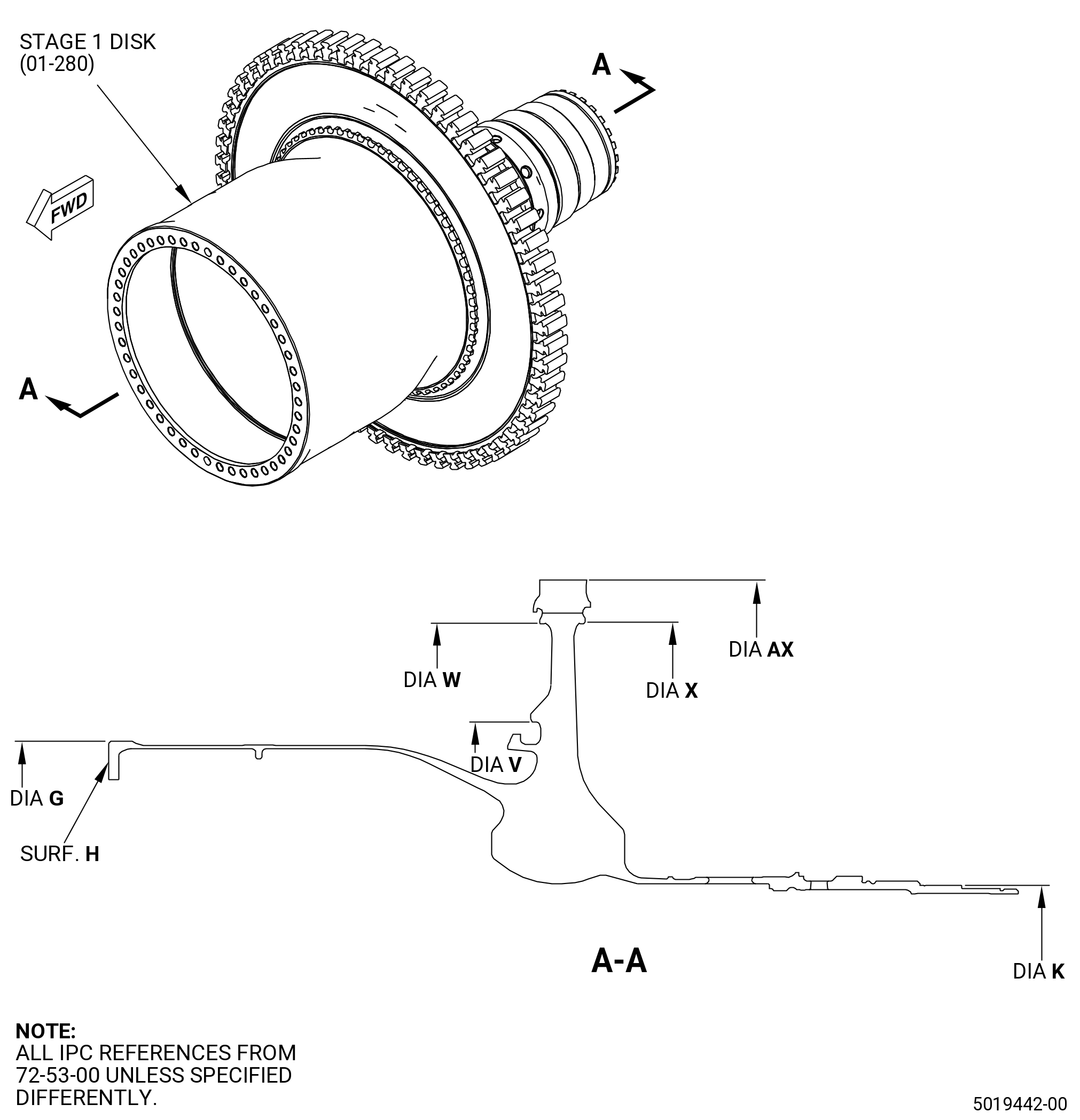
| 5 . | Dimensional Inspection. |
| Refer to Figure 815. |
| Subtask 72-53-40-220-057 |
| A. | Measure diameter AX (rim OD) at four equally spaced locations 0.720 inch (18.29 mm) from the aft end face of the post. Compare the average of the four measurements to the average of the diameters stamped on the rim. |
| Subtask 72-53-40-220-058 |
| B. | Do an inspection of the stage 1 disk for: |
| (1) | Diameter AX: |
| Minimum serviceable limit: |
|
| Maximum serviceable limit: |
|
| Repair method: |
|
| Subtask 72-53-40-220-059 |
| (2) | Diameter G: |
| Minimum serviceable limit: |
|
| Maximum serviceable limit: |
|
| Repair method: |
|
| Subtask 72-53-40-220-060 |
| (3) | Diameter W: |
| Minimum serviceable limit: |
|
| Maximum serviceable limit: |
|
| Repair method: |
|
| Subtask 72-53-40-220-061 |
| (4) | Diameter V: |
| Minimum serviceable limit: |
|
| Maximum serviceable limit: |
|
| Repair method: |
|
| Subtask 72-53-40-220-062 |
| (5) | Diameter X: |
| Minimum serviceable limit: |
|
| Maximum serviceable limit: |
|
| Repair method: |
|
| Subtask 72-53-40-220-168 |
| (6) | Concentricity of diameter K relative to the center line established from diameter G and surface H: |
| Minimum serviceable limit: |
|
| Maximum serviceable limit: |
|
| Repair method: |
|
| Subtask 72-53-40-220-063 |
| C. | Calculate and do an inspection of dimension ZZ as follows: |
| (1) | Calculate dimension XX as diameter X minus 22.480 inches (570.99 mm). |
| Subtask 72-53-40-220-064 |
| (2) | Calculate dimension YY as follows: |
| (a) | Calculate the average of the diameters AX. Refer to 72-53-40-220-058 (paragraph 5.B.(1)). |
| (b) | Subtract diameter AX stamped on the rim. |
| Subtask 72-53-40-220-065 |
| (3) | Dimension ZZ is equal to dimension YY minus dimension XX. |
| Subtask 72-53-40-220-066 |
| (4) | Do an inspection of calculated dimension ZZ for: |
| Minimum serviceable limit: |
|
| Maximum serviceable limit: |
|
| Repair method: |
|
| 6 . | Post Inspection Procedure. |
| Subtask 72-53-40-380-005 |
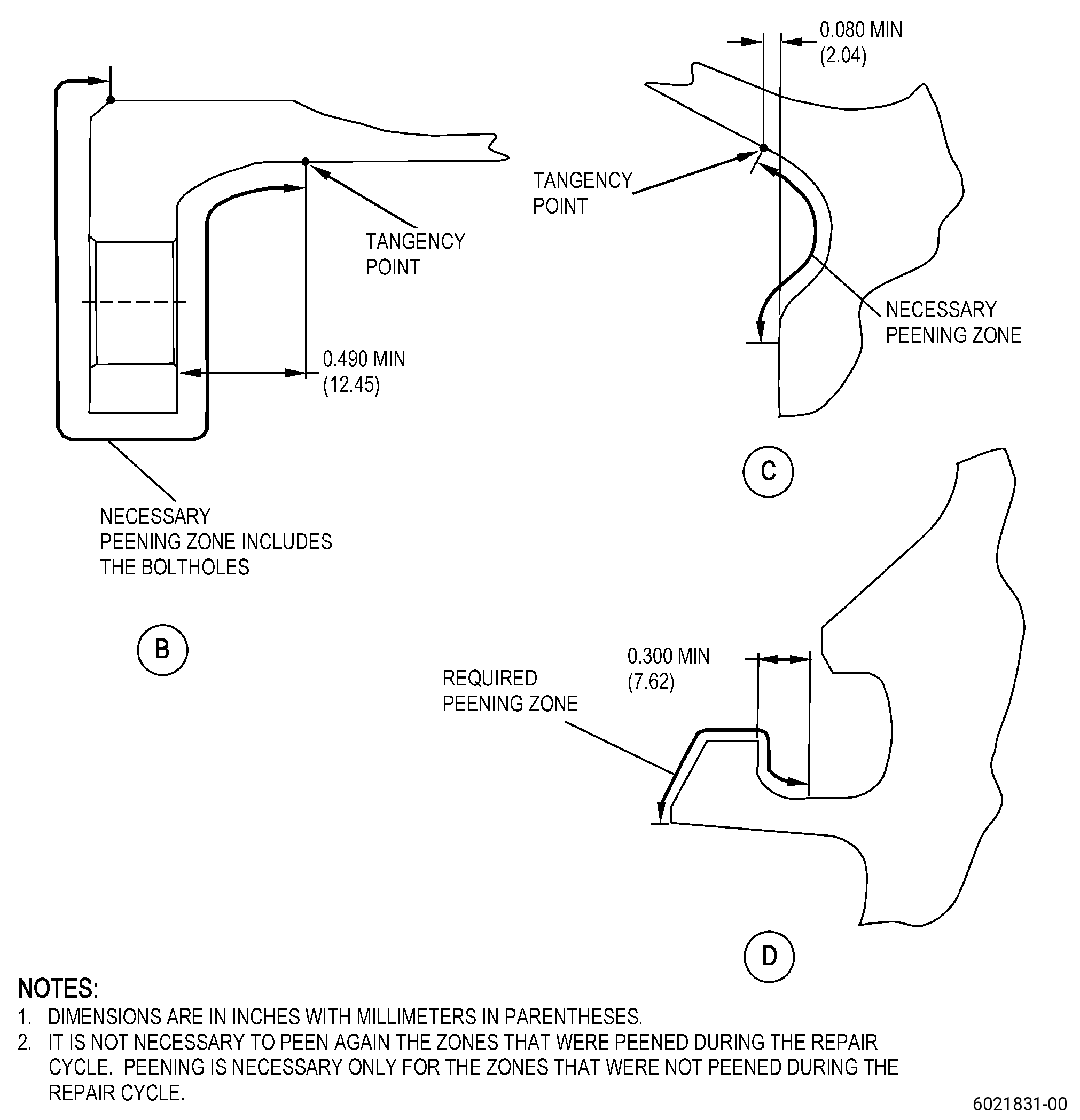
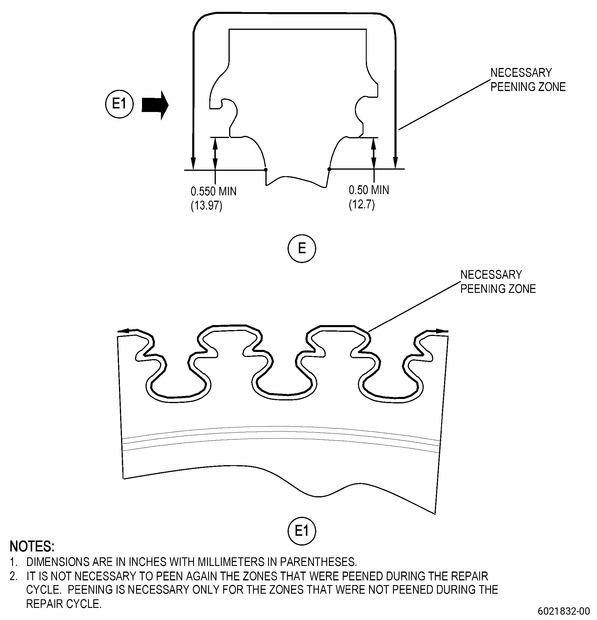
| A. | Shotpeen the surfaces in the marked zones. Refer to Figure 816 and TASK 72-53-40-300-807 (72-53-40, REPAIR 010). |
| NOTE: |
|
| (1) | Deleted. |
| (2) | Deleted. |
| (3) | Deleted. |
| (4) | Deleted. |
| (5) | Deleted. |
| (6) | Deleted. |