| GENX-1B CLEANING,INSPECTION,AND REPAIR MANUAL | Dated: 10/10/2024 | |
| CIR 72-30-01 , REPAIR 004 | ||
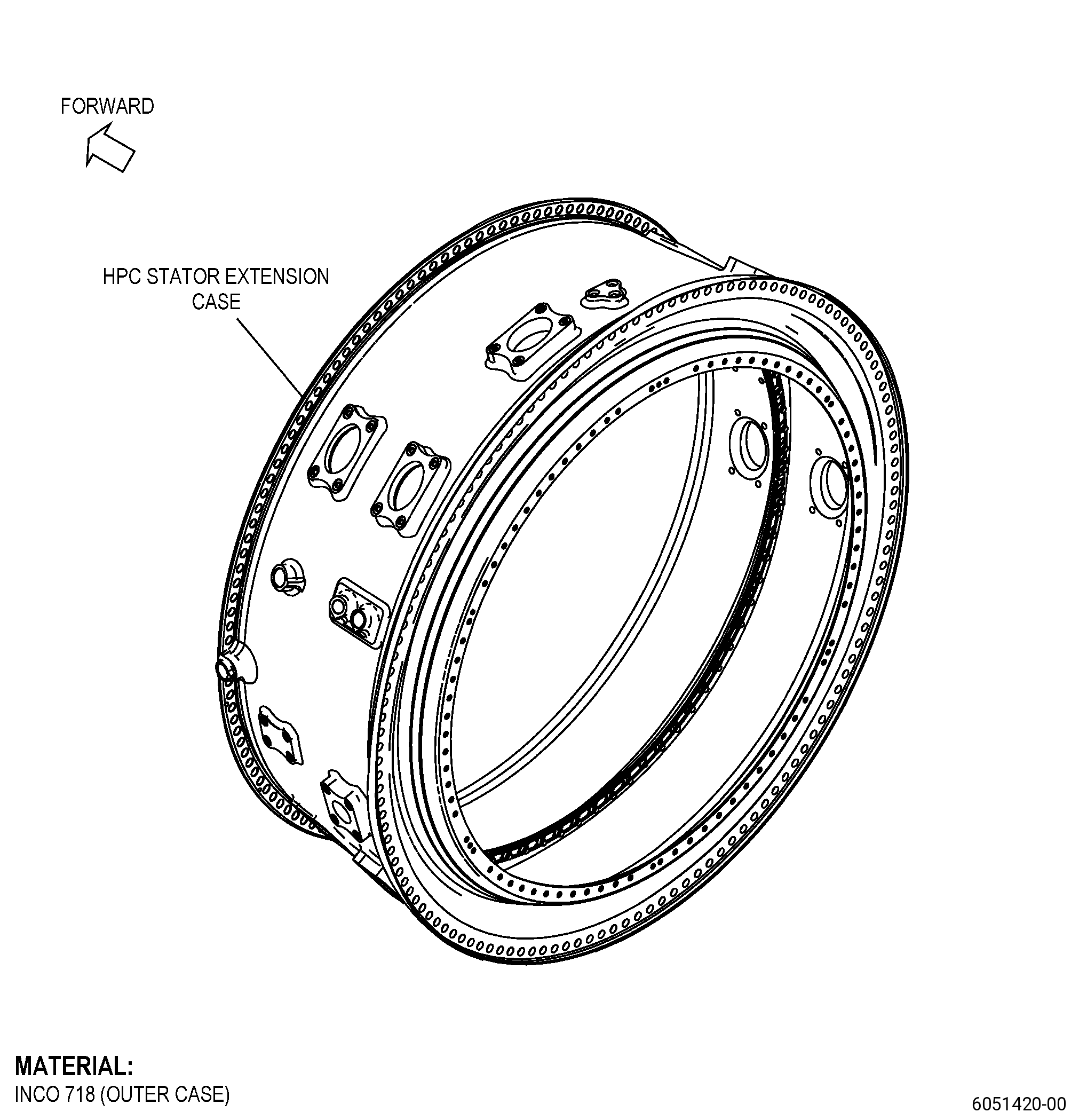
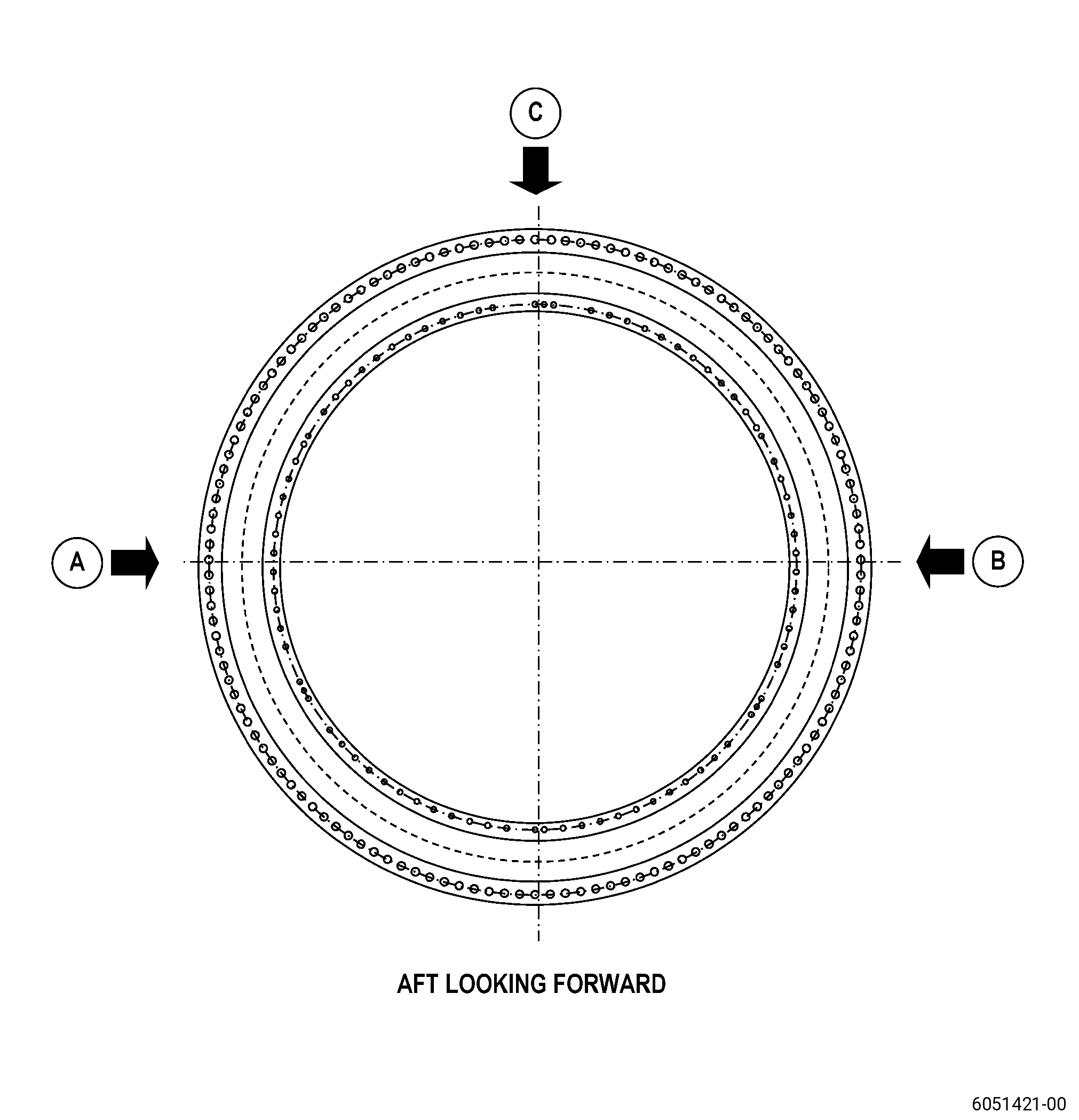
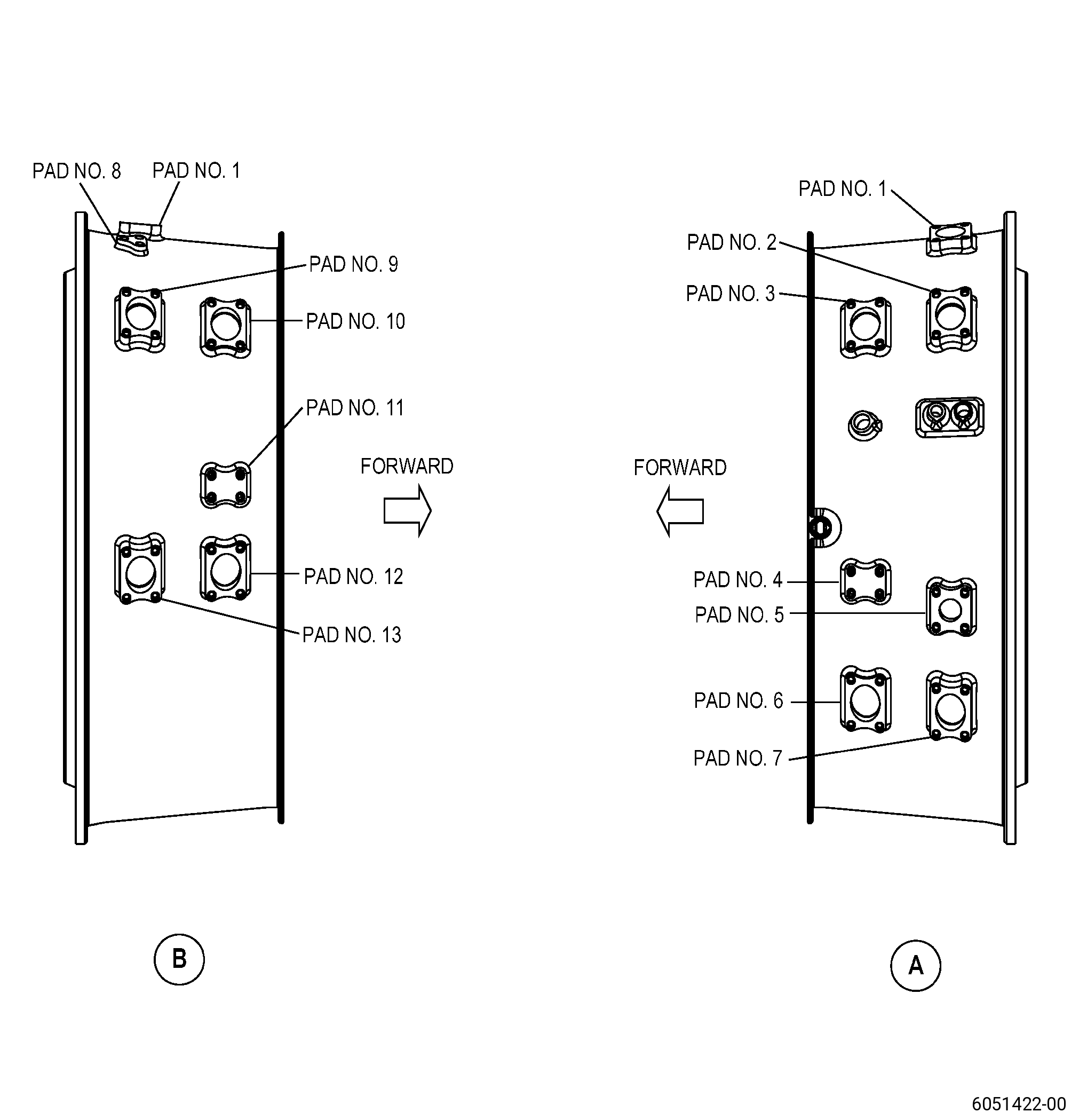
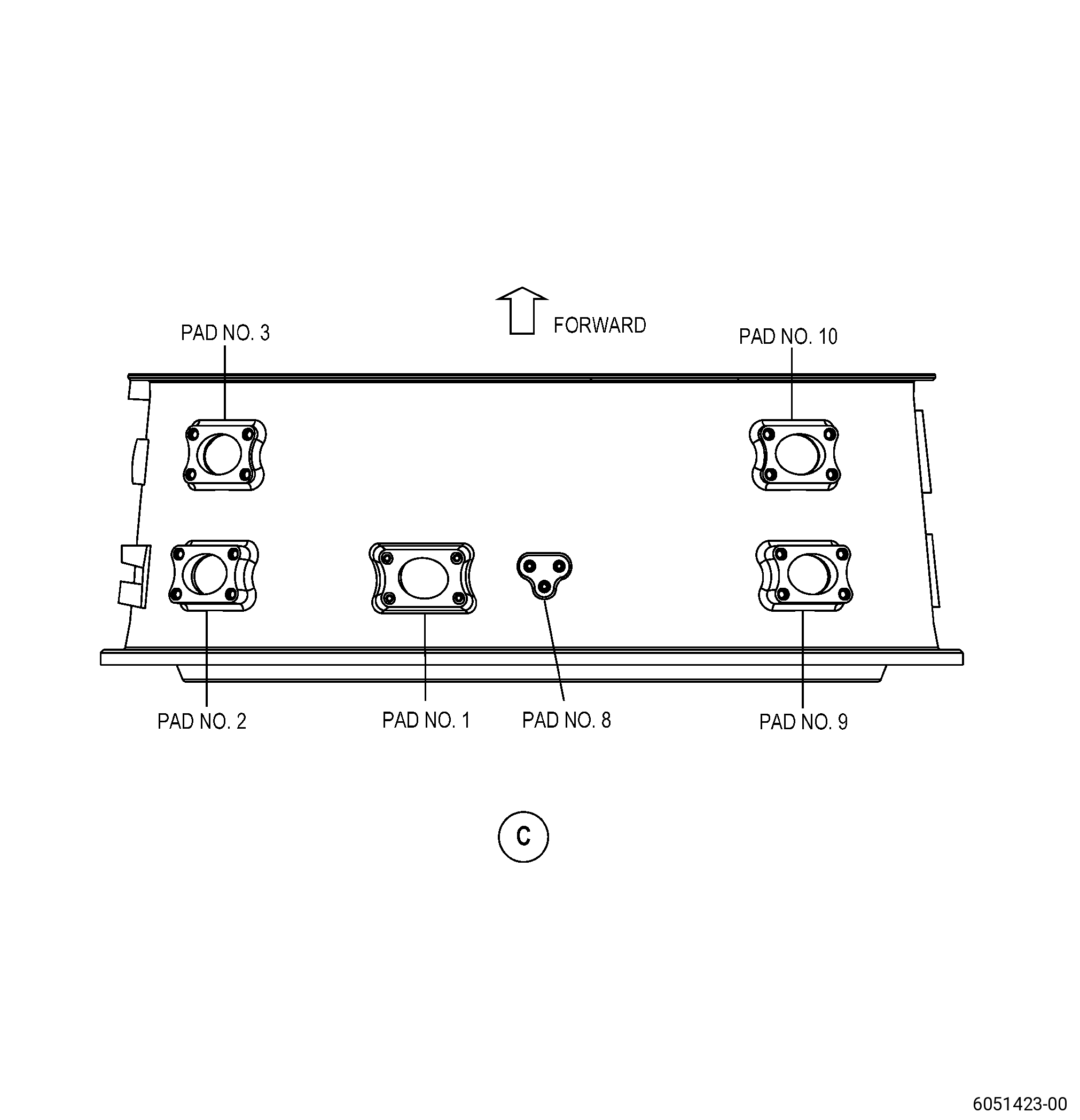
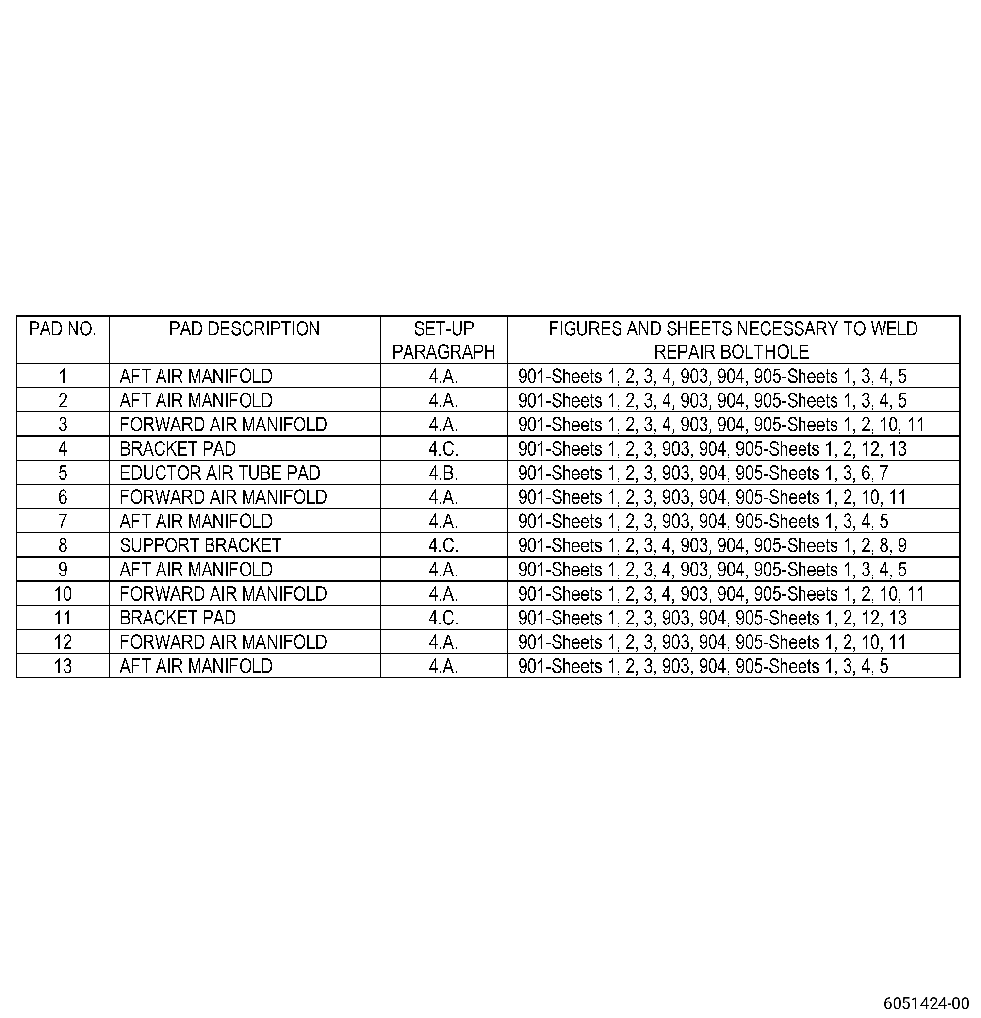
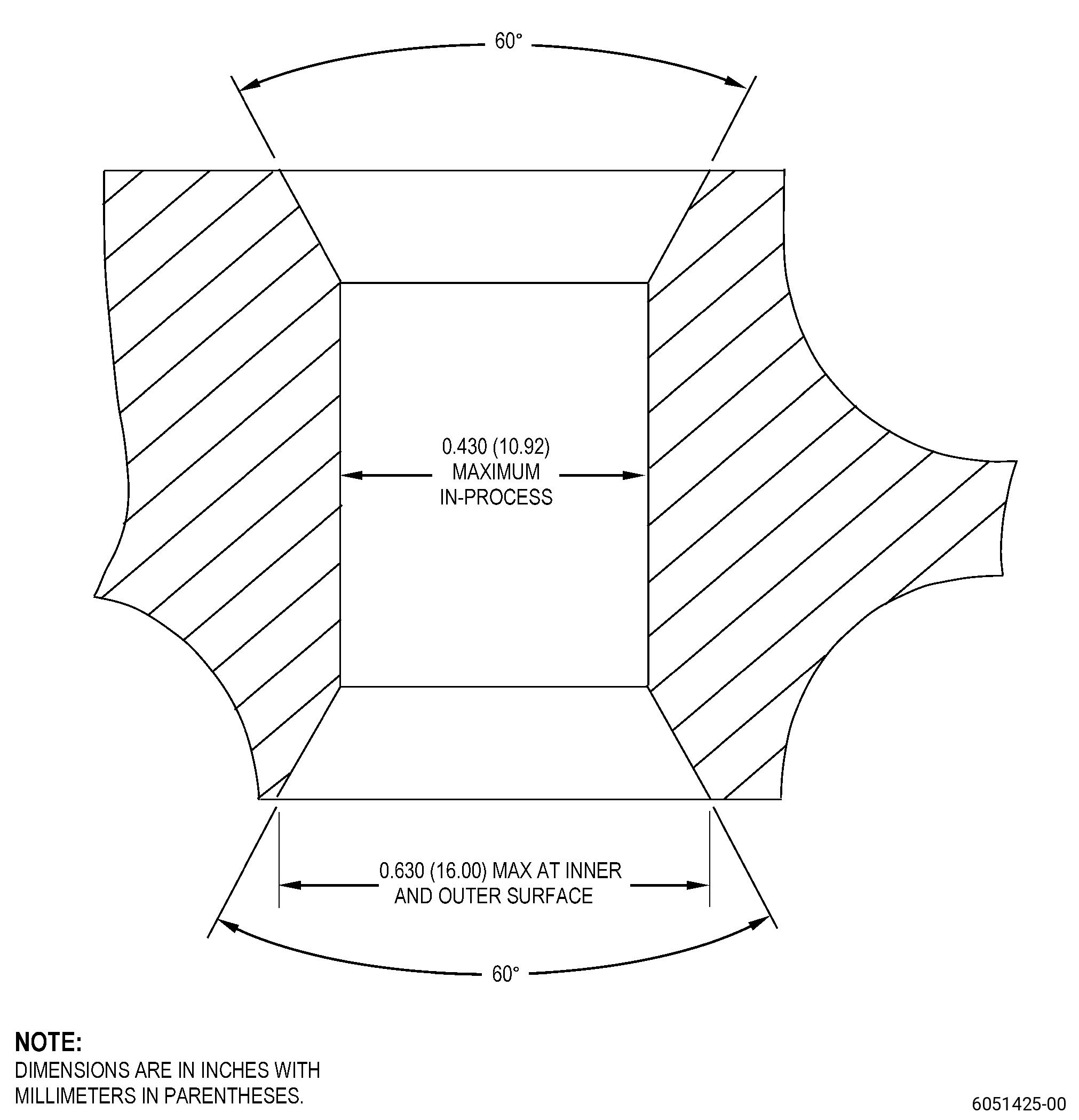
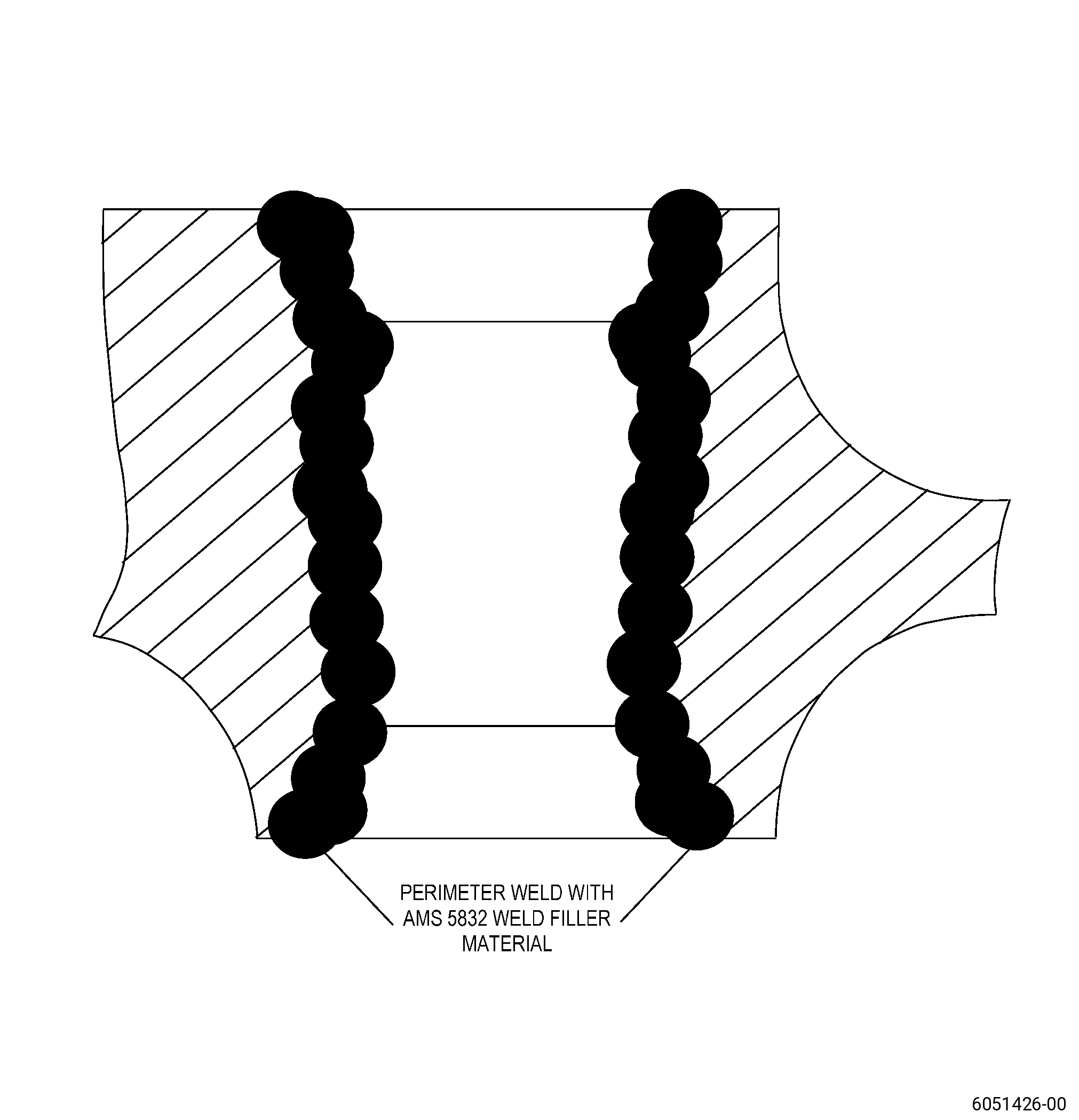
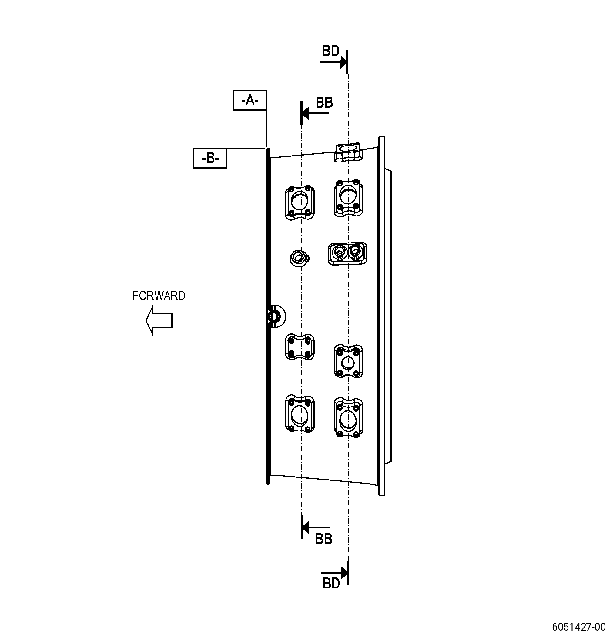
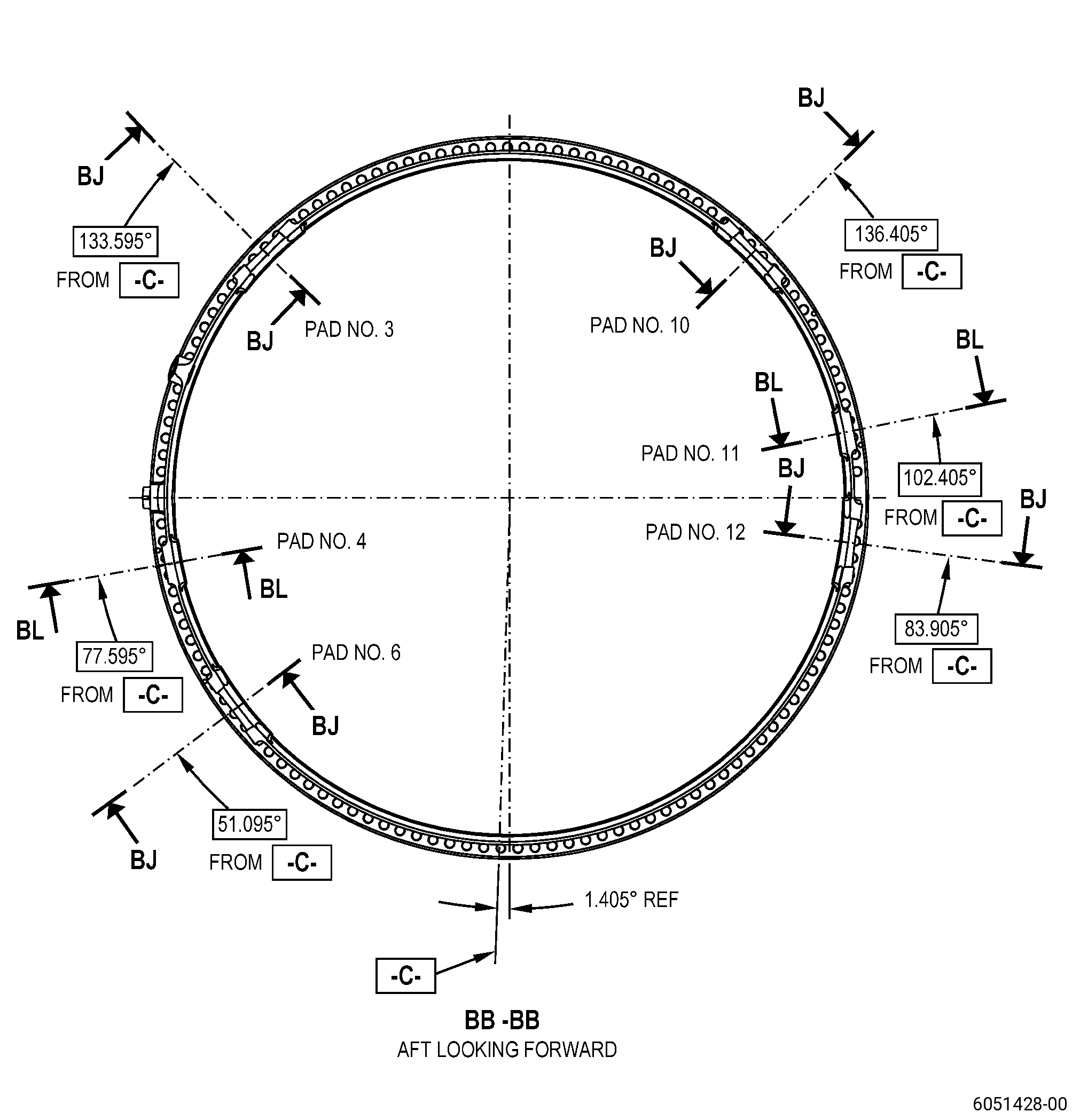
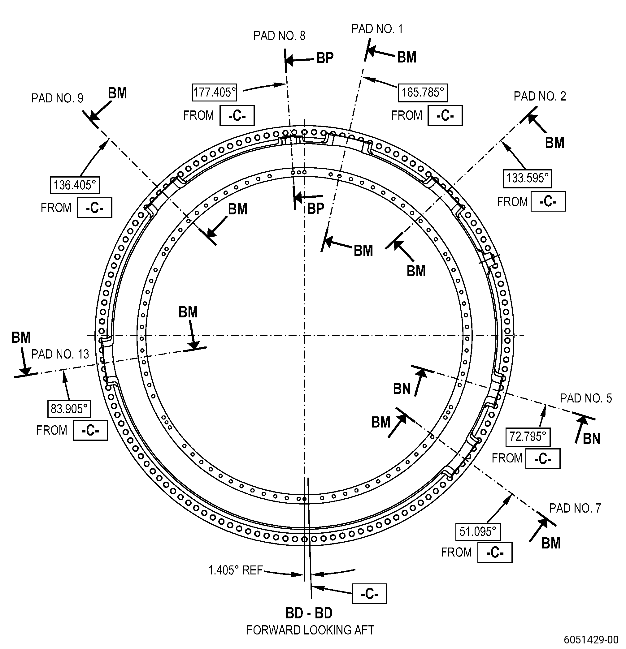
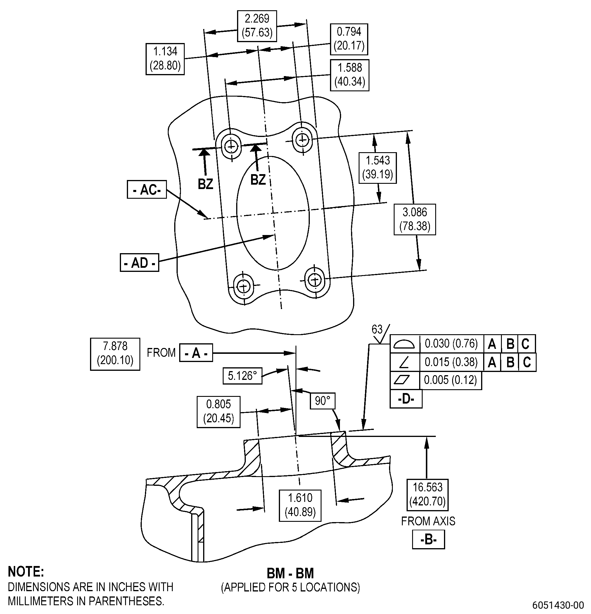
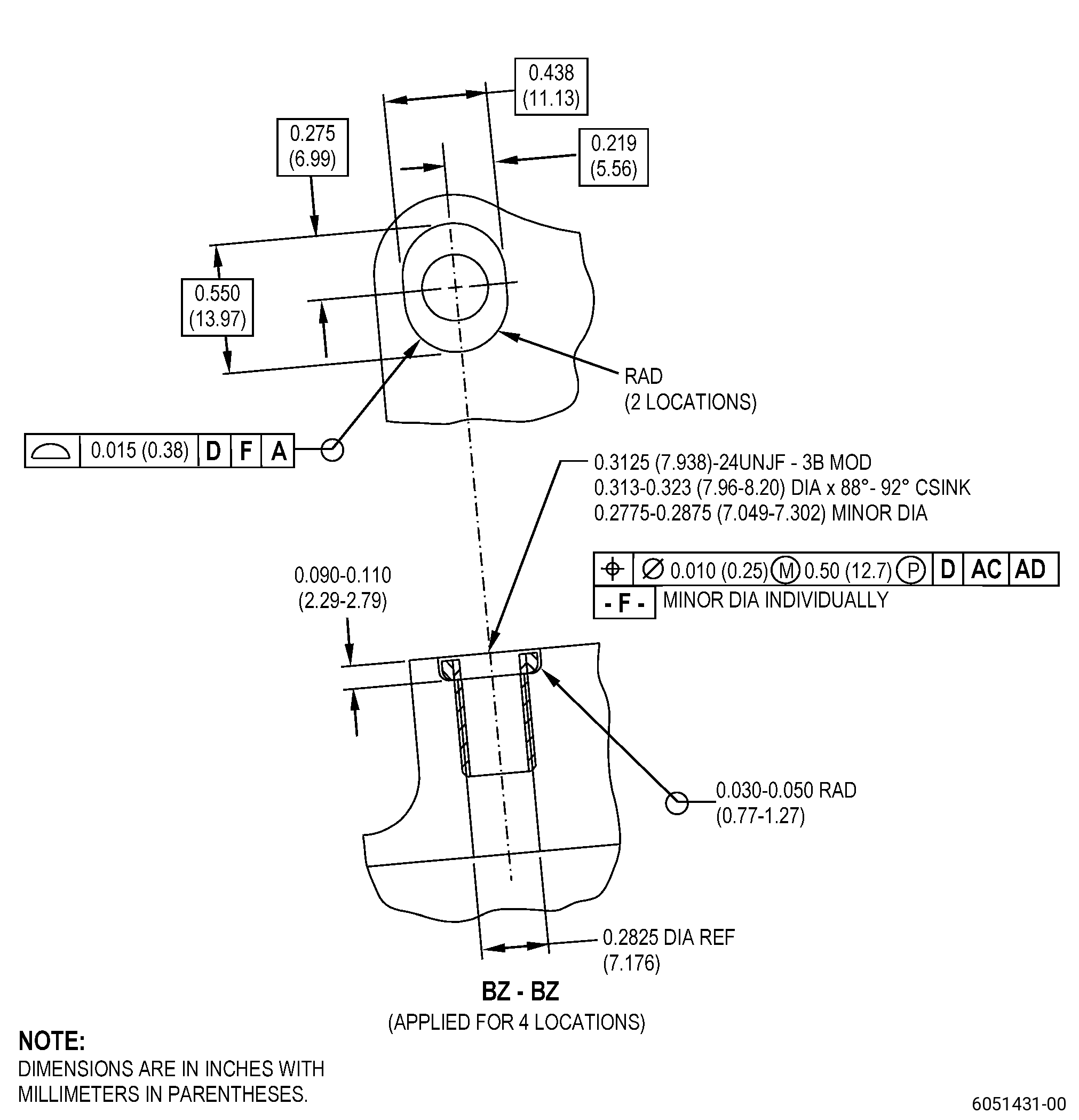
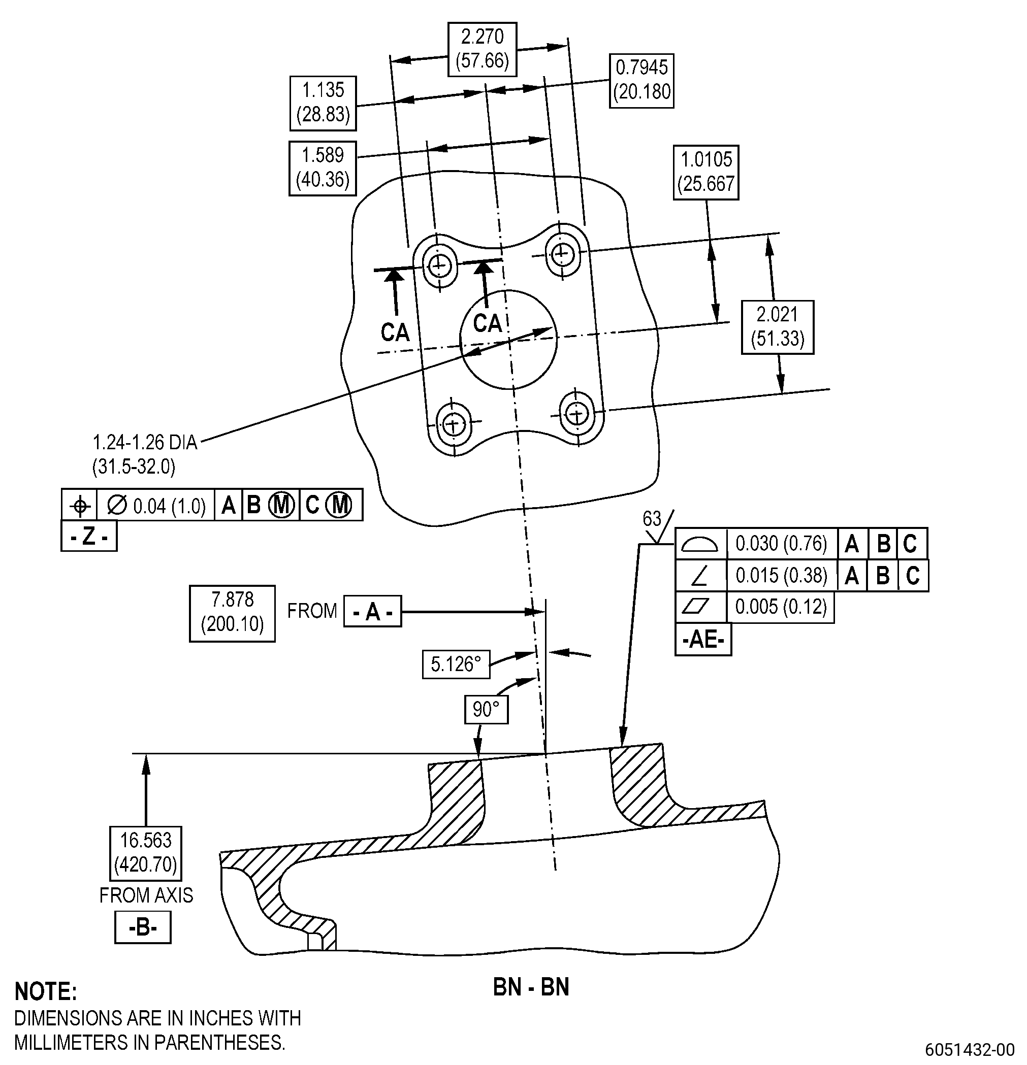
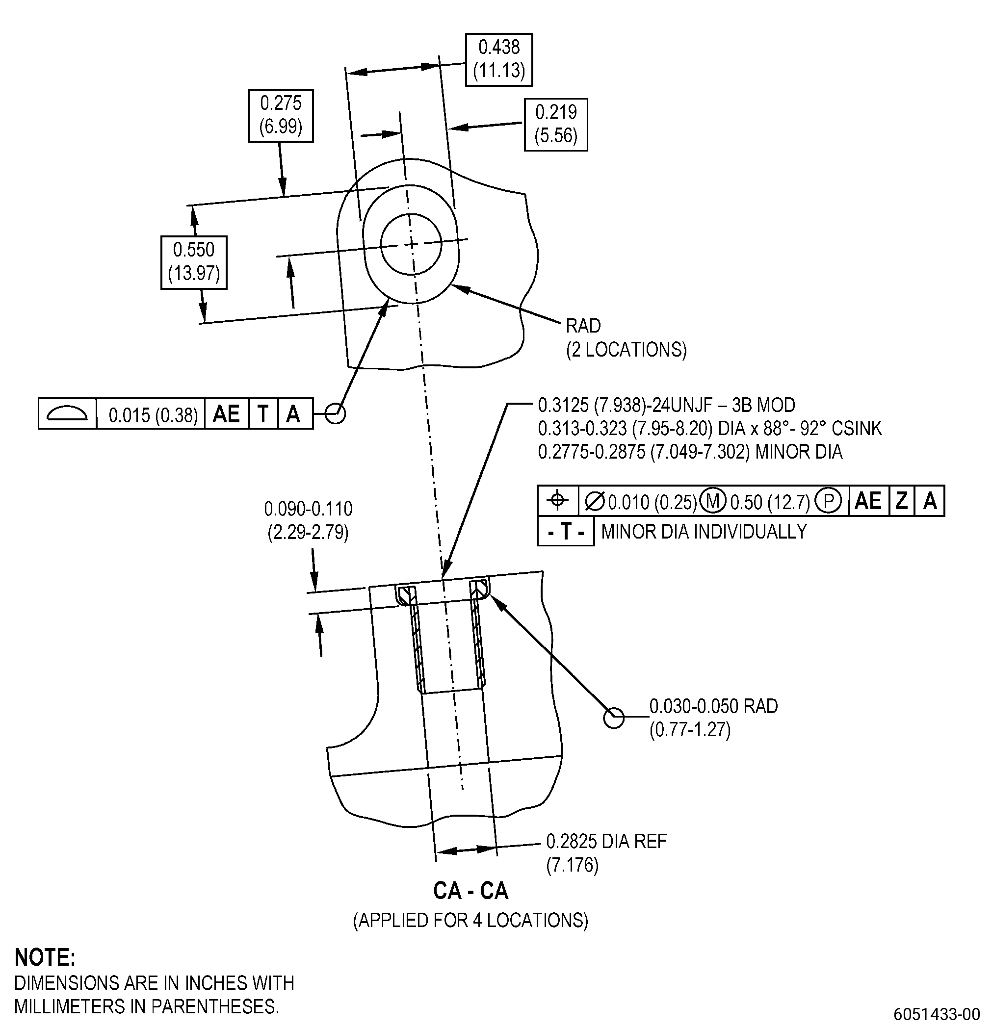
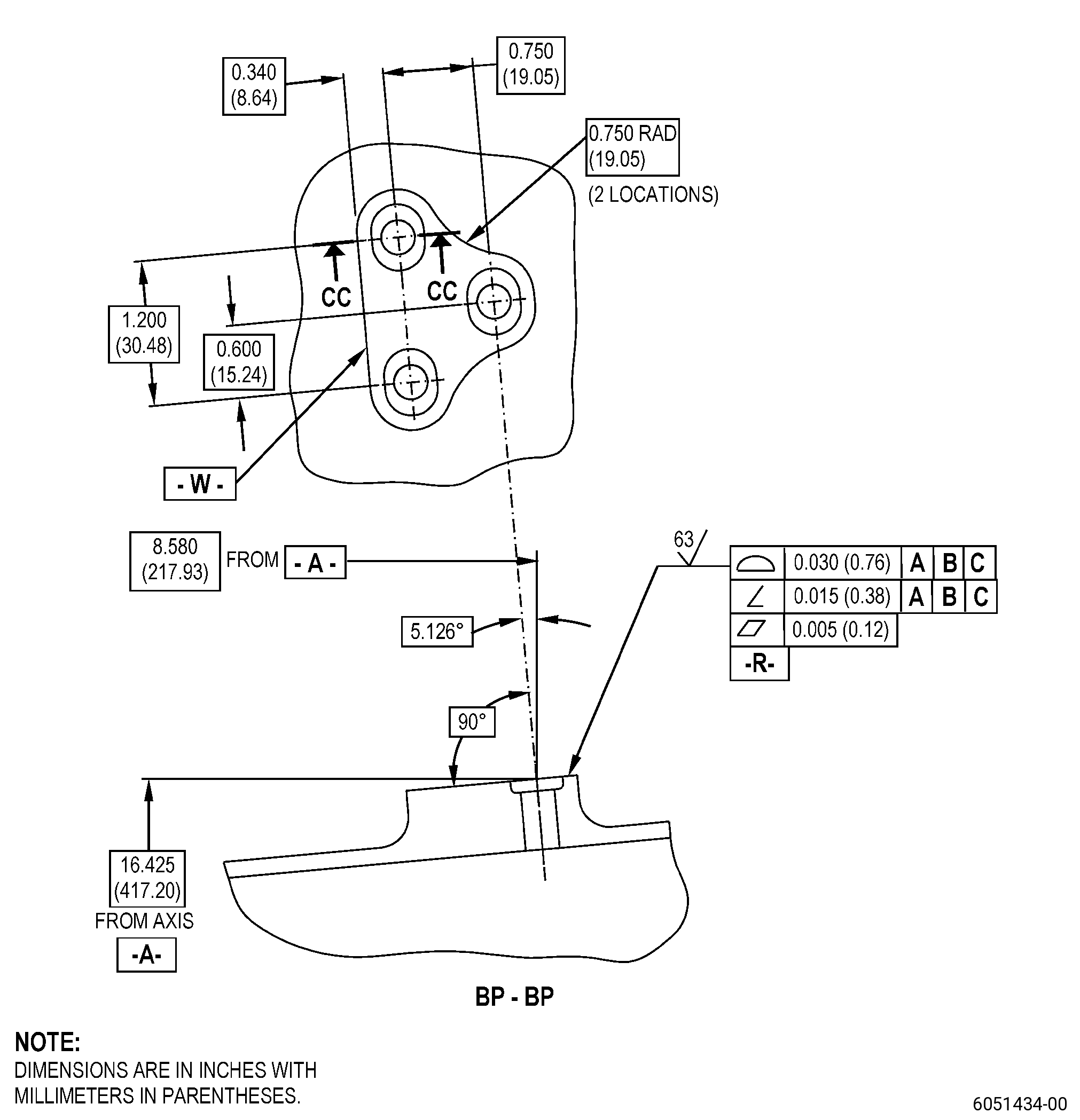
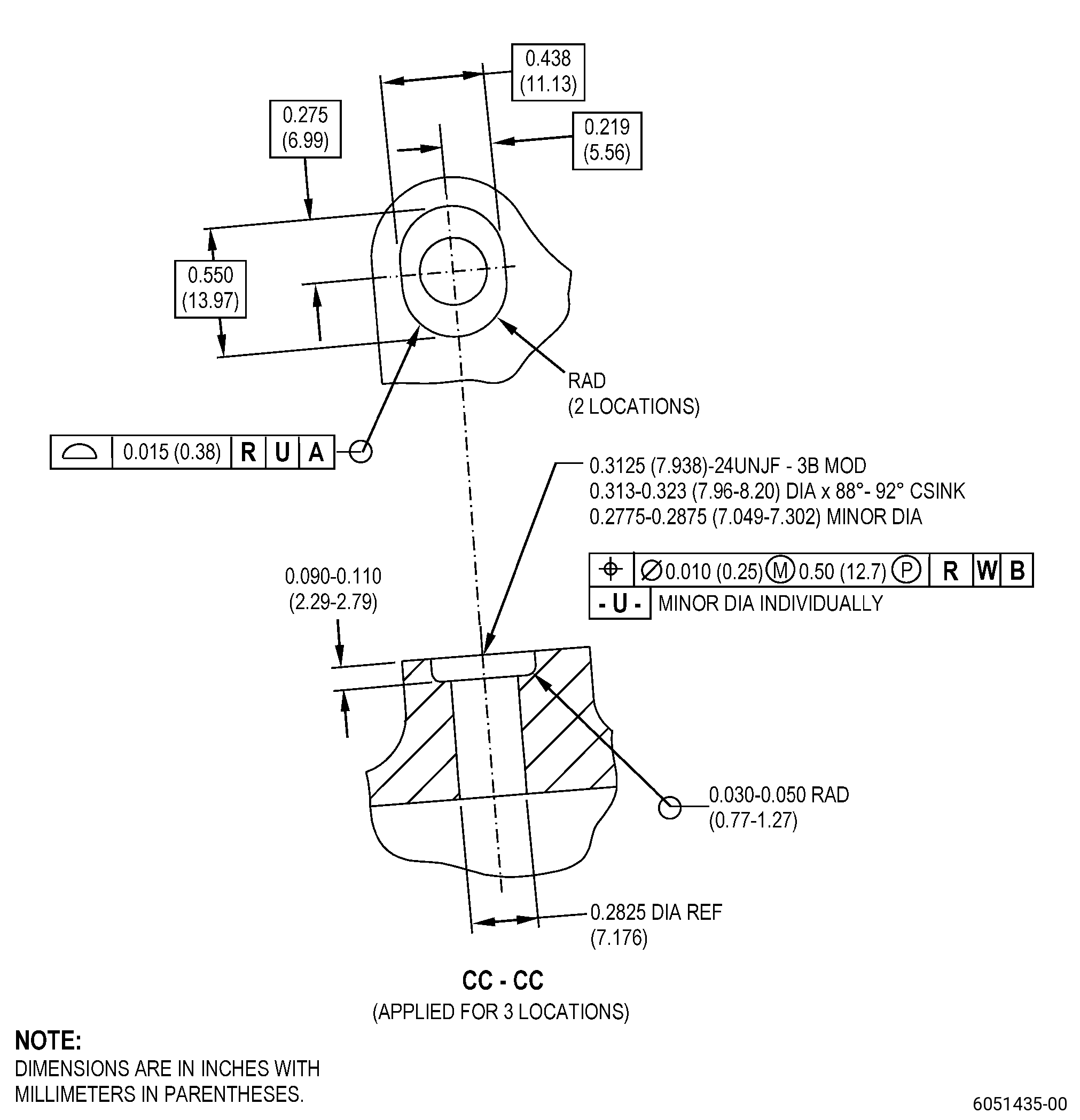
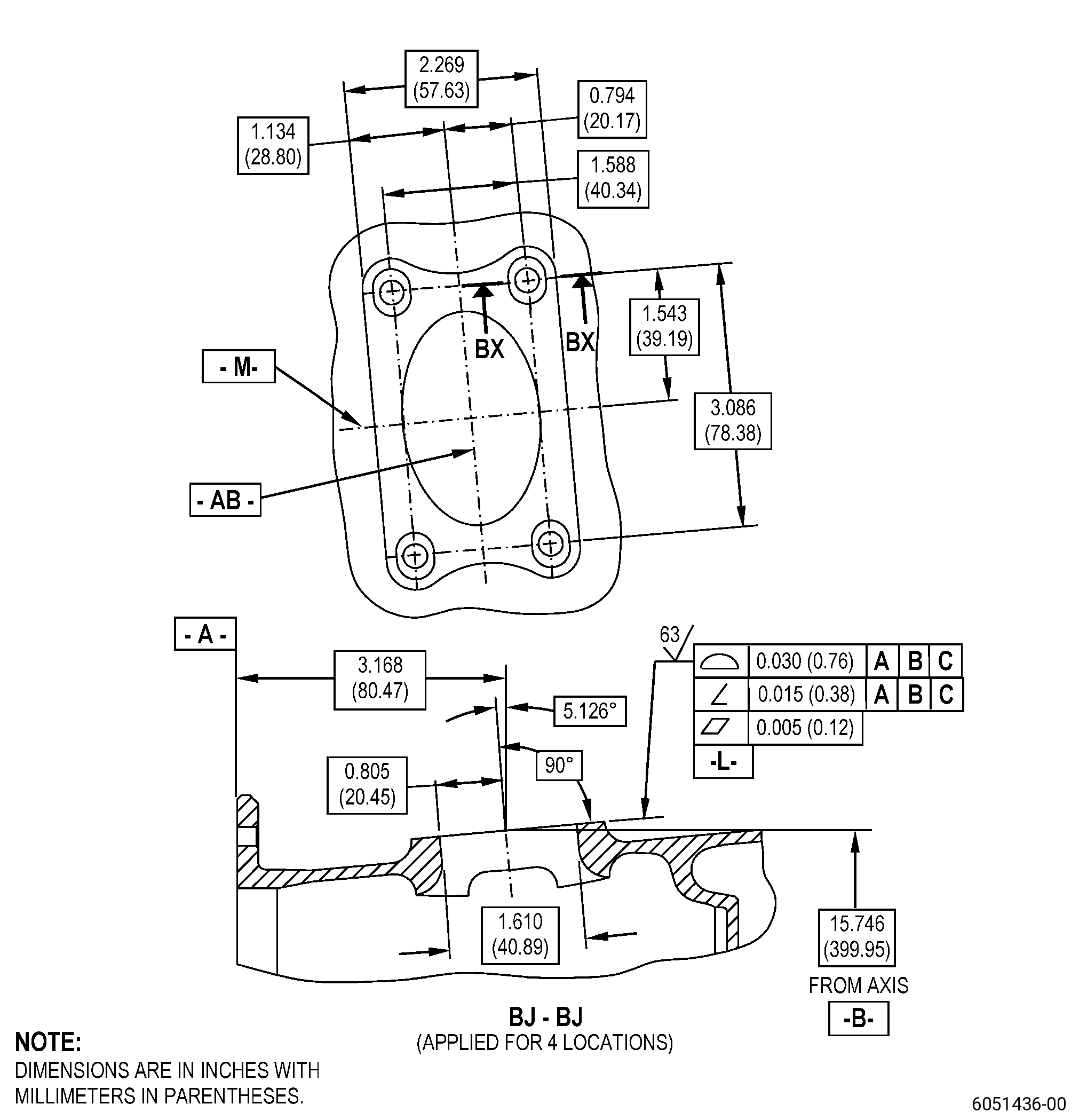
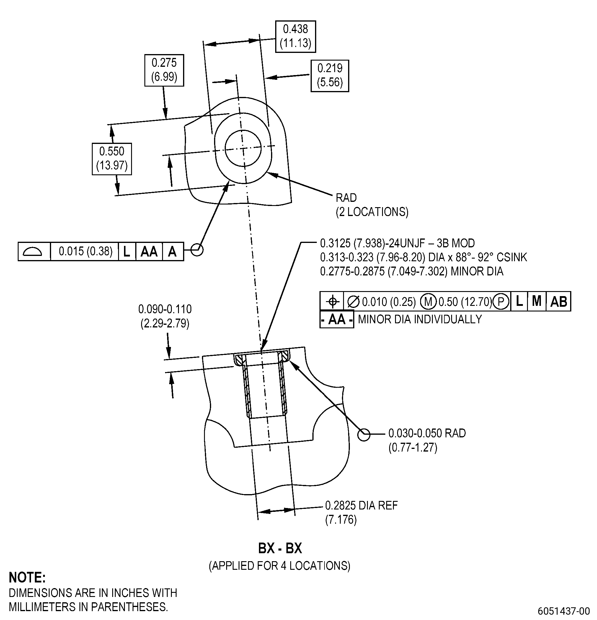
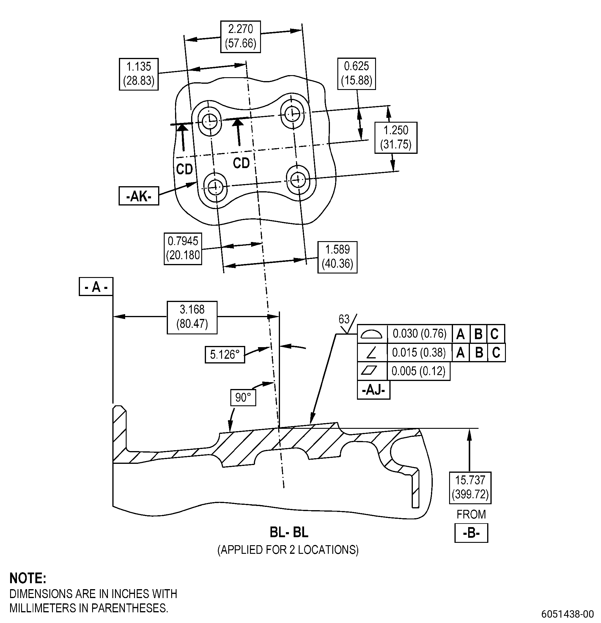
| HIGH PRESSURE COMPRESSOR STATOR EXTENSION CASE - REPAIR - WELD REPAIR OF THE DAMAGED BOLTHOLE THREADS ON THE EXTENSION CASE PADS OF THE HIGH PRESSURE COMPRESSOR | ||