| GENX-1B CLEANING,INSPECTION,AND REPAIR MANUAL | Dated: 12/22/2020 | |
| CIR 72-31-41 , REPAIR 002 | ||
| HIGH PRESSURE COMPRESSOR STAGE 1 BLISK - REPAIR - THERMAL SPRAY REPAIR OF DIAMETER AY | ||
| GENX-1B CLEANING,INSPECTION,AND REPAIR MANUAL | Dated: 12/22/2020 | |
| CIR 72-31-41 , REPAIR 002 | ||
| HIGH PRESSURE COMPRESSOR STAGE 1 BLISK - REPAIR - THERMAL SPRAY REPAIR OF DIAMETER AY | ||
| * * * FOR ALL |
| TASK 72-31-41-300-803 |
| 1 . | Thermal Spray Repair of Diameter AY. |
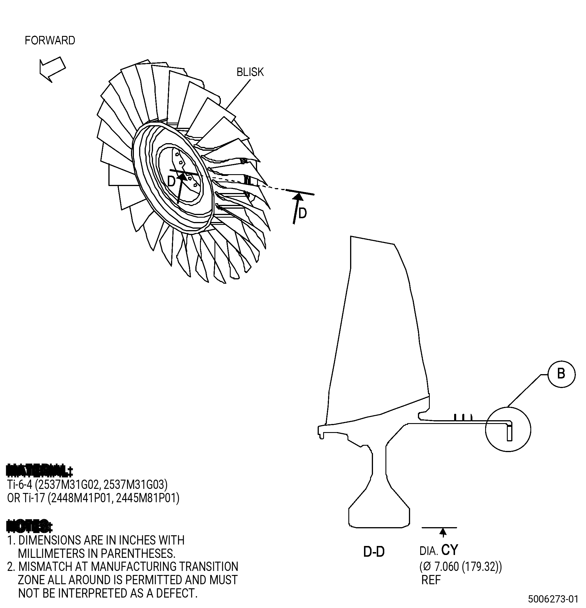
| A. | This procedure gives instructions to repair the high pressure compressor stage 1 blisk (blisk) by thermal spraying diameter AY. Refer to Figure 901. |
| B. | The following maximum repairable limits apply to this repair: |
| NOTE: |
|
| NOTE: |
|
| (5) | Visual Inspection. |
| (i) | Do an inspection of the flange for: |
| 3 | Fretting, galling, and wear on diameter AY: |
| Maximum Repairable Limit: |
|
| 4 | Nicks, dents, pits, and scratches on diameter AY: |
| Maximum Repairable Limit: |
|
| (6) | Special Dimensional Inspection. |
| (c) | Measure the dimensions that follow: |
| 4 | Diameter AY: |
| Minimum Repairable Limit: |
|
| 5 | Roundness of Diameter AY: |
| Maximum Repairable Limit: |
|
| C. | The subsequent table gives a list of the part numbers that are applicable to this repair. All part numbers are applicable to all paragraphs unless specified differently. |
|
|||||||||||||||||||||||||||
| D. | Proprietary/Complex Process Statement. |
| (1) | None. |
| 2 . | Tools, Equipment, and Materials. |
| NOTE: |
|
| A. | Tools and Equipment. |
| (1) | Special Tools. None. |
| (2) | Standard Tools and Equipment. None. |
| (3) | Locally Manufactured Tools. None. |
| B. | Consumable Materials. |
| C. | Referenced Procedures. |
|
| D. | Expendable Parts. None. |
| E. | SPD Information. |
| (1) | Locally Manufactured SPD. None. |
| F. | Special Solutions. None. |
| G. | Test Specimens. Refer to TASK 70-49-21-340-022 (THERMAL SPRAYING NICKEL-CHROMIUM/ALUMINUM COMPOSITE (POWDER)) . |
| 3 . | Dimensional Information. |
| Subtask 72-31-41-220-080 |
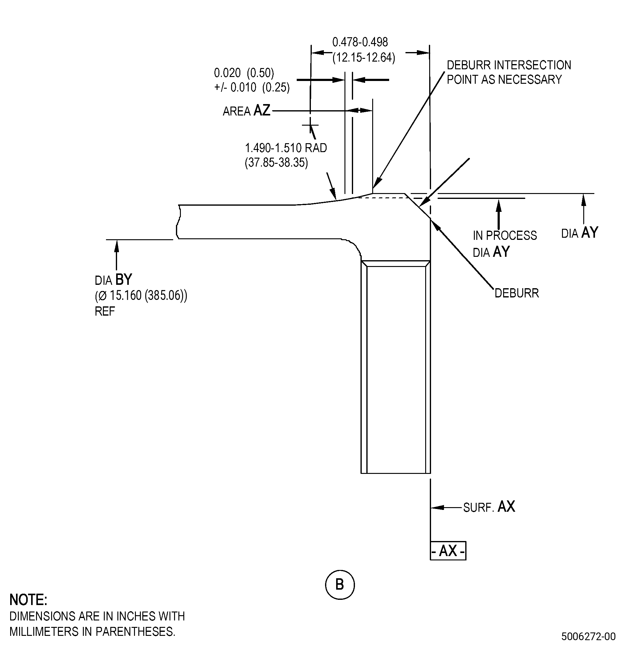
| A. | Refer to Figure 901 for specified dimensions and locations. |
| NOTE: |
|
| NOTE: |
|
|
| 4 . | Setup Information. |
| Subtask 72-31-41-350-004 |
| A. | Set-up the blisk to machine diameter AY as follows: |
| (1) | The runout of surface AX must be 0.006 inch (0.15 mm) or less. |
| (2) | The runout of diameter AY must be 0.0015 inch (0.038 mm) or less. If its not possible to get the runout with diameter AY, use bore diameter CY. The runout of diameter CY must be 0.001 inch (0.02 mm) or less. Refer to Figure 901. |
| 5 . | Procedure. |
| Subtask 72-31-41-160-006 |
| A. | If necessary, clean the blisk. Refer to TASK 72-31-41-100-801 (72-31-41, CLEANING 001). |
| Subtask 72-31-41-350-005 |
| B. | Apply a masking to the blisk airfoils and do not remove it until Subtask 72-31-41-350-006 (paragraph 5.L.). Refer to Figure 901 and do as follows: |
| (1) | Use C10-012 tape. |
| Subtask 72-31-41-330-001 |
| CAUTION: |
|
| C. | If necessary, remove all thermal spray coating from the blisk diameter AY. Refer to TASK 70-23-00-100-001 (STRIPPING PROCEDURES) and TASK 70-23-23-330-008 (REMOVAL OF COATINGS BY HIGH PRESSURE WATER STRIPPING). |
| Subtask 72-31-41-320-001 |
| D. | Machine the blisk. Refer to TASK 70-00-03-800-004 (MACHINING DATA), Subtask 72-31-41-220-080 (paragraph 3.A.), Figure 901, and as follows: |
| (1) | Set-up the blisk to machine diameter AY. Refer to Subtask 72-31-41-350-004 (paragraph 4.A.). |
| (2) | Machine diameter AY to agree with the in-process dimensions. |
| (3) | Break sharp edges to 0.005-0.015 inch (0.13-0.38 mm). |
| Subtask 72-31-41-160-007 |
| E. | Steam clean the spool. Refer to TASK 70-21-00-110-051 (CHEMICAL CLEANING) and TASK 70-21-03-160-001 (CLEANING METHOD NO. 3 - STEAM CLEANING). |
| Subtask 72-31-41-110-006 |
| F. | Etch the blisk diameter AY. Refer to TASK 70-24-00-110-033 (ETCHING PROCEDURES FOR FLUORESCENT-PENETRANT INSPECTION), TASK 70-24-01-110-034 (SWAB ETCHING PROCEDURE), and as follows: |
| (1) | Use Class B etchant. |
| Subtask 72-31-41-230-006 |
| G. | Do an inspection of diameter AY. Refer to TASK 70-32-00-200-002 (INDIRECT INSPECTION METHODS), TASK 70-32-03-230-002 (SPOT-FLUORESCENT-PENETRANT INSPECTION), and as follows: |
| (1) | Use Class G penetrant. |
| (2) | Linear indications are not permitted. |
| NOTE: |
|
| (3) | Indications that go across corners are not permitted. |
| (4) | Indications 0.015 inch (0.38 mm) or less are permitted. |
| NOTE: |
|
| Subtask 72-31-41-380-003 |
| H. | Peen the blisk. Refer to TASK 70-47-01-380-016 (SHOTPEENING) and as follows: |
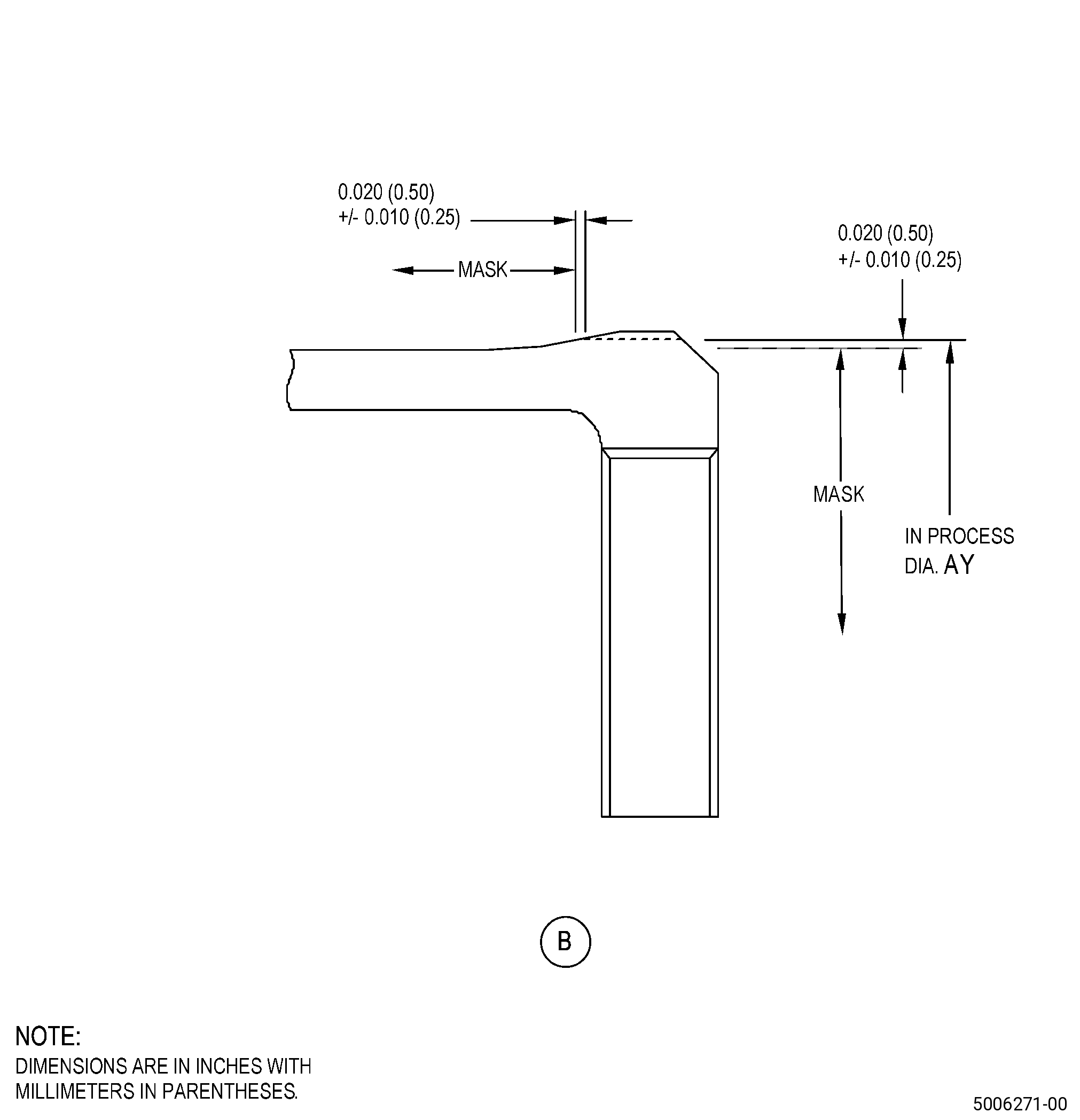
| (1) | Apply masking to the blisk. Refer to Figure 902 and as follows: |
| (a) | Use C10-021 plastic tape. |
| (2) | Use C04-271 S110 steel shot. |
| (3) | Intensity must be 0.006-0.012N. |
| (4) | Overspray is not permitted. |
| (5) | Remove the masking. |
| Subtask 72-31-41-340-001 |
| I. | Thermal-spray the blisk and the test specimens. Refer to TASK 70-49-00-340-001 (THERMAL SPRAYING), TASK 70-49-21-340-022 (THERMAL SPRAYING NICKEL-CHROMIUM/ALUMINUM COMPOSITE (POWDER)), and as follows: |
| (1) | Apply masking to the blisk areas that you will not thermal spray. Refer to Figure 902 and as follows: |
| (a) | Use C10-012 tape. |
| WARNING: |
|
| (2) | Grit-blast diameter AY as follows: |
| (a) | Do all preliminary operations specified in TASK 70-49-00-340-001 (THERMAL SPRAYING). |
| (b) | The final surface finish must agree with titanium base material. |
| (3) | Apply thermal spray coating to diameter AY, chamfer area, and to the test specimens as follows: |
| (a) | Make sure that you apply thermal spray coating to the test specimens at the same time and to the same thickness as diameter AY and chamfer area. |
| (b) | The minimum coating thickness after the final machining must be 0.008 inch (0.21 mm). |
| (c) | Apply sufficient thermal spray coating to machine the blisk diameter AY to the finish dimensions. |
| (d) | The maximum as-sprayed coating thickness is 0.040 inch (1.01 mm). |
| (4) | Remove the masking. |
| (5) | Do all quality assurance testing specified in TASK 70-49-21-340-022 (THERMAL SPRAYING NICKEL-CHROMIUM/ALUMINUM COMPOSITE (POWDER)). |
| Subtask 72-31-41-320-002 |
| J. | Machine the blisk. Refer to TASK 70-00-03-800-004 (MACHINING DATA), Subtask 72-31-41-220-080 (paragraph 3.A.), Figure 901, and as follows: |
| (1) | Set-up the blisk to machine diameter AY. Refer to Subtask 72-31-41-350-004 (paragraph 4.A.). |
| (2) | Machine diameter AY to the finish dimensions and as follows: |
| Subtask 72-31-41-220-081 |
| (a) | The surface finish must be 63 microinches (1.6 micrometers) or better and the circularity must be less than 0.0015 inch (0.038 mm). |
| Subtask 72-31-41-320-003 |
| (b) | Machine to clean up coating build-up on chamfer. |
| NOTE: |
|
| (c) | Machine to clean up coating build-up in area AZ. |
| NOTE: |
|
| Subtask 72-31-41-220-082 |
| K. | Do a visual inspection of the blisk to make sure that there are no cracks, chipping, or flaking of the coating. |
| Subtask 72-31-41-350-006 |
| L. | Remove the masking that you applied in Subtask 72-31-41-350-005 (paragraph 5.B.) from the blisk airfoils. |
| Subtask 72-31-41-160-008 |
| M. | Steam clean the spool. Refer to TASK 70-21-00-110-051 (CHEMICAL CLEANING) and TASK 70-21-03-160-001 (CLEANING METHOD NO. 3 - STEAM CLEANING). |