| GENX-1B CLEANING,INSPECTION,AND REPAIR MANUAL | Dated: 01/19/2023 | |
| CIR 72-31-46 , REPAIR 001 | ||
| COMPRESSOR DISCHARGE PRESSURE ROTATING SEAL - REPAIR - SEAL TEETH THERMAL SPRAY REPAIR | ||
| GENX-1B CLEANING,INSPECTION,AND REPAIR MANUAL | Dated: 01/19/2023 | |
| CIR 72-31-46 , REPAIR 001 | ||
| COMPRESSOR DISCHARGE PRESSURE ROTATING SEAL - REPAIR - SEAL TEETH THERMAL SPRAY REPAIR | ||
| * * * FOR ALL |
| TASK 72-31-46-300-801 |
| 1 . | Repair for the Compressor Discharge Pressure Rotating Seal. |
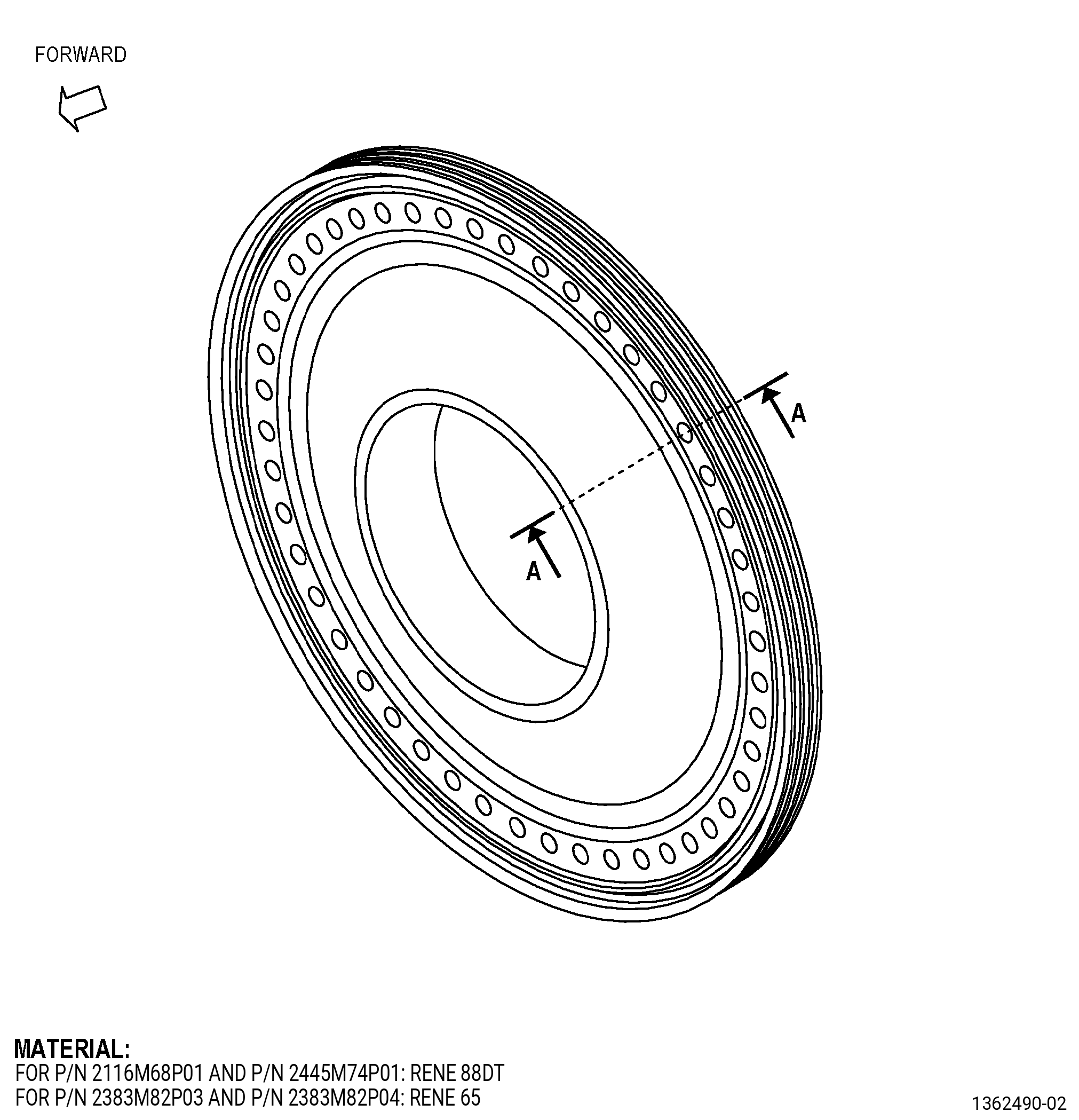
| A. | This procedure gives instructions to repair the high pressure compressor discharge pressure (CDP) rotating seal (seal) by replacing the thermal spray coating on the seal teeth. Refer to Figure 901. |
| B. | The following maximum repairable limits apply to this repair: |
| NOTE: |
|
| (4) | Visual Inspection. |
| (i) | Do an inspection of the seal serrations for: |
| 2 | Missing Coating: |
| Maximum repairable limit: |
|
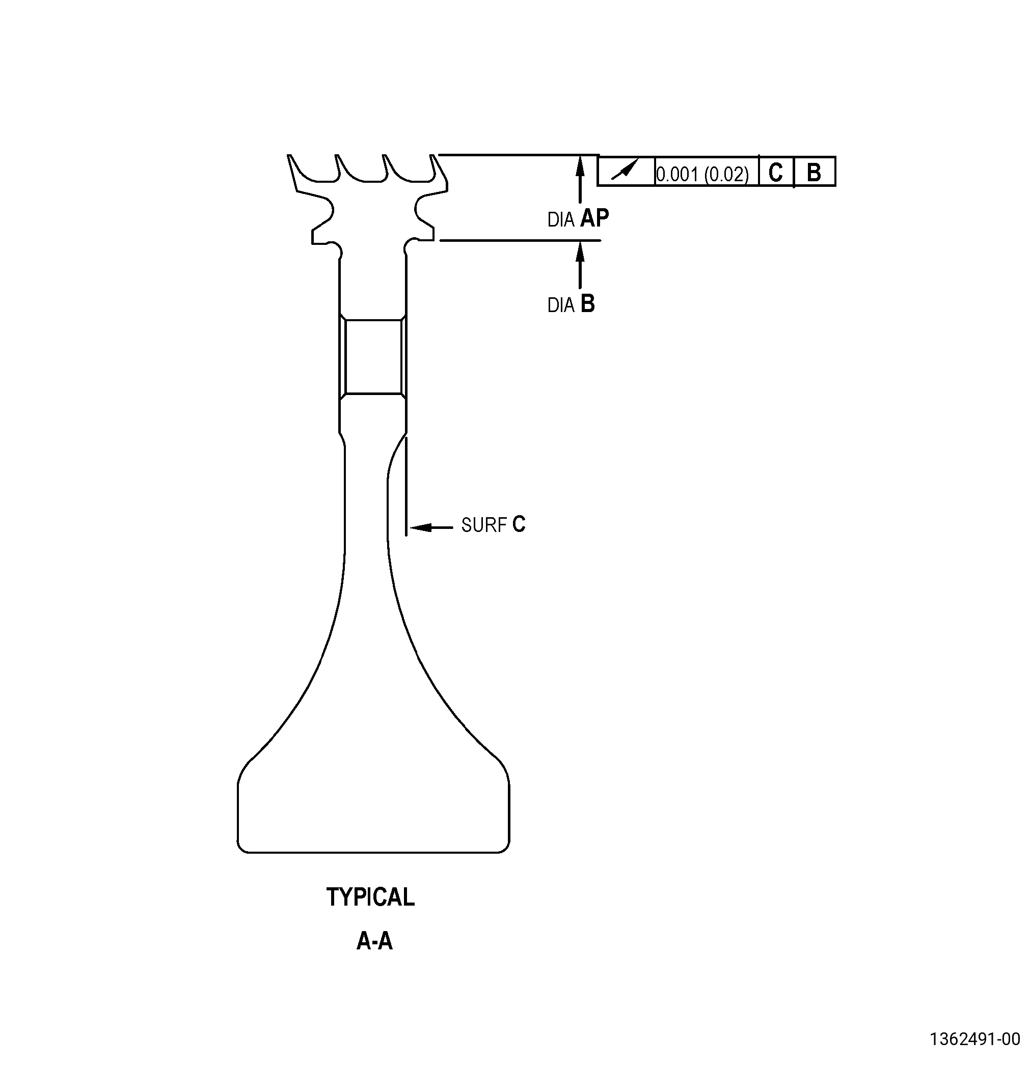
| (5) | Dimensional Inspection. |
| (c) | Do an inspection of the CDP seal diameters for: |
| 3 | Diameter AP (free state) (without coating): |
| Minimum repairable limit: |
|
| C. | The subsequent table gives a list of the part numbers that are applicable to this repair. All part numbers are applicable to all paragraphs unless specified differently. |
|
|||||||||||||||||||||||
| D. | Proprietary/Complex Process Statement. |
| (1) | None. |
| 2 . | Tools, Equipment, and Materials. |
| NOTE: |
|
| A. | Tools and Equipment. |
| (1) | Special Tools. None. |
| (2) | Standard Tools and Equipment. None. |
| (3) | Locally Manufactured Tools. |
|
| B. | Consumable Materials. |
| C. | Referenced Procedures. |
|
| D. | Expendable Parts. None. |
| E. | SPD Information. None. |
| F. | Special Solutions. None. |
| G. | Test Specimens. None. |
| 3 . | Dimensional Information. |
| Subtask 72-31-46-220-030 |
| A. | Refer to Figure 901 for specified dimensions and locations. |
| NOTE: |
|
|
| 4 . | Setup Information. |
| Subtask 72-31-46-930-001 |
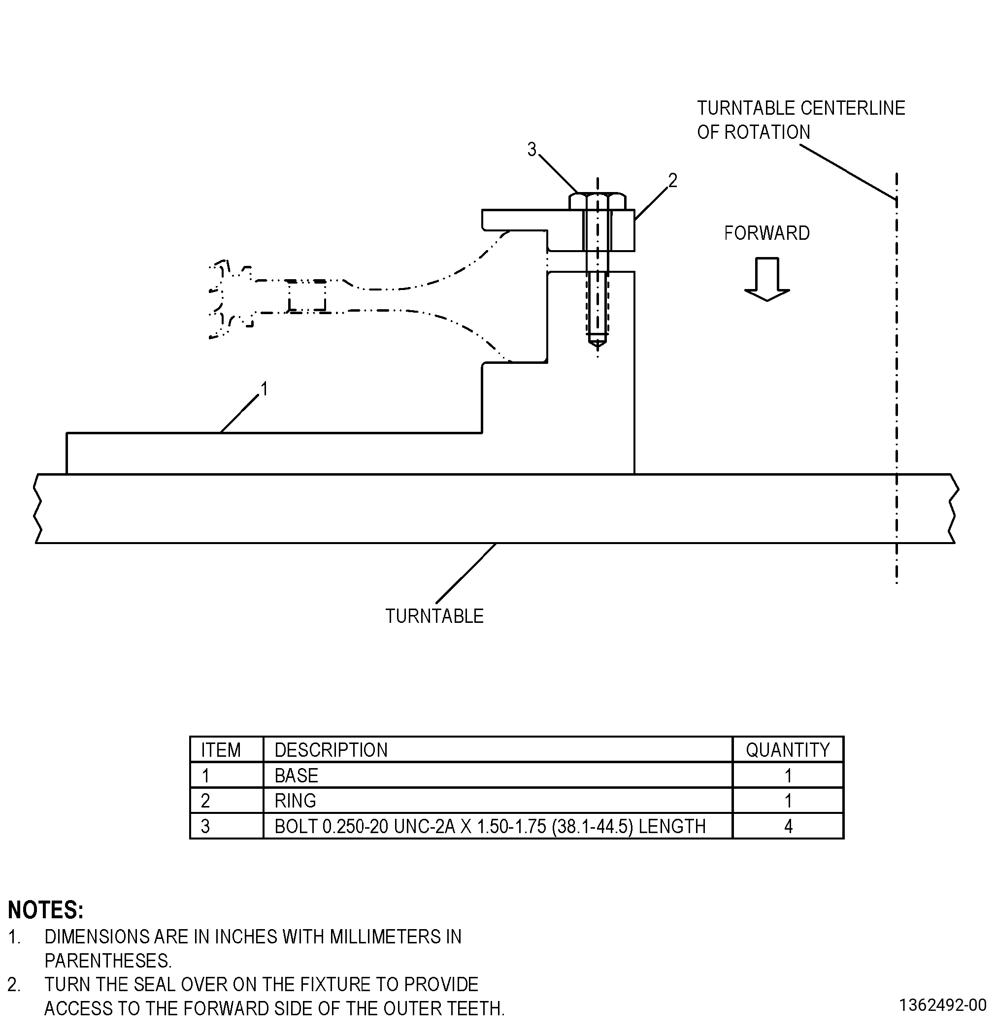
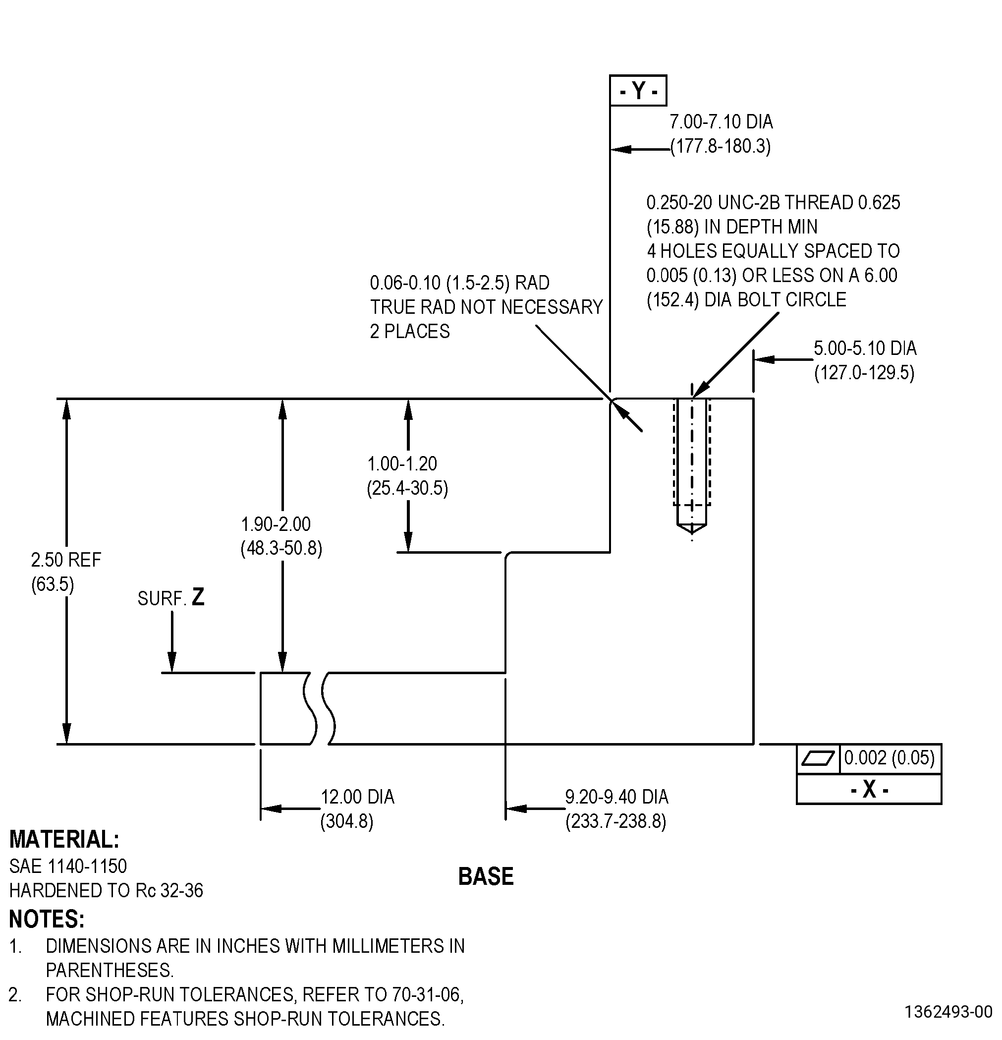
| A. | If necessary, make the locally manufactured thermal spray holding fixture (holding fixture). Refer to Figure 902. |
| Subtask 72-31-46-350-003 |
| B. | Set-up the holding fixture. Refer to Figure 902 and as follows: |
| (1) | Put the holding fixture on the rotating table. |
| (2) | Diameter Y must be concentric with the axis of rotation to 0.050 inch (1.27 mm) or less. |
| (3) | Surface Z must have a runout of 0.050 inch (1.27 mm) or less. |
| (4) | Put the seal on the holding fixture with the aft side up and put the holding fixture ring on the seal. |
| (5) | Diameter AP must have a runout of 0.050 inch (1.27 mm) or less. |
| (6) | Surface C must have a runout of 0.050 inch (1.27 mm) or less. |
| (7) | Tighten the bolts. Refer to TASK 70-51-00-400-004 (TIGHTENING PRACTICES AND TORQUE VALUES). |
| Subtask 72-31-46-930-002 |
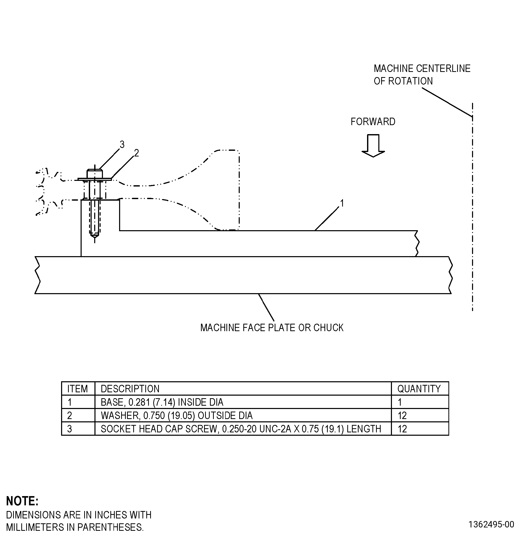
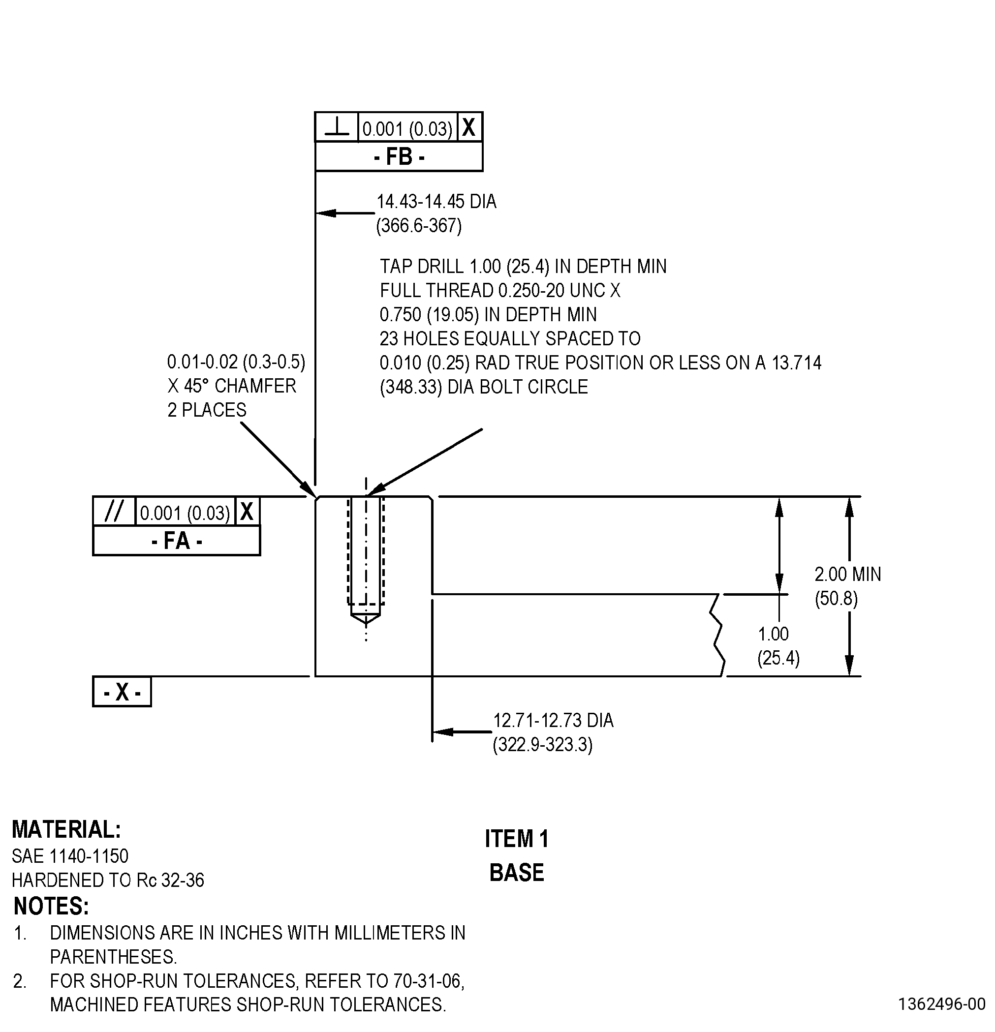
| C. | If necessary, make the locally manufactured machining fixture (machining fixture). Refer to Figure 903. |
| Subtask 72-31-46-350-005 |
| D. | Set-up the machining fixture. Refer to Figure 901, Figure 903, and as follows: |
| (1) | Put the machining fixture on the machine. |
| (2) | Diameter FB must be concentric with the axis of rotation to 0.001 inch (0.02 mm) or less. |
| (3) | The runout of surface FA must be 0.001 inch (0.02 mm) or less. |
| (4) | Set-up the seal on the machining fixture as follows: |
| (a) | Put the seal in the machining fixture base with the aft side up. |
| (b) | Install 12 washers and bolts equally spaced through the seal and into the machining fixture. |
| (c) | Diameter B must have a runout of 0.001 inch (0.02 mm) or less. |
| (d) | Surface C must have a runout of 0.001 inch (0.02 mm) or less. |
| (e) | Tighten the bolts. Refer to TASK 70-51-00-400-004 (TIGHTENING PRACTICES AND TORQUE VALUES). |
| 5 . | Procedure. |
| Subtask 72-31-46-100-007 |
| CAUTION: |
|
| A. | If necessary, clean the seal. Refer to TASK 72-31-46-100-001 (72-31-46, CLEANING 001). |
| Subtask 72-31-46-350-007 |
| B. | Remove the coating from the seal teeth as follows: |
| (1) | Set-up the seal in the holding fixture. Refer to Figure 902, Subtask 72-31-46-930-001 (paragraph 4.A.), and Subtask 72-31-46-350-003 (paragraph 4.B.). |
| CAUTION: |
|
| (2) | Remove the coating from the seal teeth as follows: |
|
||||||||||||||||||||||||||||||||||||||||||||||||||||||||||||||||||||||||||||||||||||
| Subtask 72-31-46-100-005 |
| (3) | Deleted. |
| Subtask 72-31-46-100-006 |
| B.A. | Deleted. |
| Subtask 72-31-46-220-035 |
| C. | Do a dimensional inspection of the seal teeth in-process dimension. Refer to Subtask 72-31-46-220-030 (paragraph 3.A.), Dimensional Information and as follows: |
| Subtask 72-31-46-320-002 |
| (1) | If necessary, machine the seal teeth. Refer to TASK 70-00-03-800-004 (MACHINING DATA) and as follows: |
| (a) | Set-up the seal for machining. Refer to Subtask 72-31-46-930-002 (paragraph 4.C.), Setup Information and Subtask 72-31-46-350-008 (paragraph 4.D.), Setup Information. |
| NOTE: |
|
| (b) | Machine the seal teeth to remove the damage and to make the part agree with the in-process dimensions. |
| Subtask 72-31-46-220-036 |
| (c) | The runout to diameter B must be 0.002 inch (0.05 mm) maximum. |
| Subtask 72-31-46-350-008 |
| D. | Blend the burrs and rolled edges from the seal teeth. Refer to TASK 70-42-00-350-002 (BLENDING AND REMOVAL OF HIGH METAL PROCEDURES) and as follows: |
| (1) | Break the edges to 0.0050 inch (0.127 mm) maximum. |
| Subtask 72-31-46-100-001 |
| E. | Clean the seal. Refer to TASK 70-21-00-110-051 (CHEMICAL CLEANING) and TASK 70-21-03-160-001 (CLEANING METHOD 3 - STEAM CLEANING). |
| Subtask 72-31-46-110-016 |
| F. | Etch the repair area. Refer to TASK 70-24-00-110-033 (ETCHING PROCEDURES FOR FLUORESCENT-PENETRANT INSPECTION), TASK 70-24-01-110-034 (SWAB ETCHING PROCEDURE), and as follows: |
| (1) | Use Class C etchant. |
| Subtask 72-31-46-200-003 |
| G. | Do an inspection of the seal teeth. Refer to TASK 70-32-00-200-002 (INDIRECT INSPECTION METHODS), TASK 70-32-03-230-002 (SPOT-FLUORESCENT-PENETRANT INSPECTION), and as follows: |
| (1) | Use Class G penetrant. |
| (2) | Indications more than 0.015 inch (0.38 mm) are not permitted. |
| Subtask 72-31-46-380-001 |
| H. | Peen area BD of the seal. Refer to TASK 70-47-01-380-016 (SHOTPEENING) and do as follows: |
| (1) | Set-up the seal for shotpeening. Refer to Subtask 72-31-46-350-003 (paragraph 4.B.), Setup Information. |
| (2) | Apply C10-021 plastic tape to areas that have thermal spray coating. |
| (3) | Use C04-166 CCW14 shot. |
| (4) | Peen to an intensity of 0.006-0.012N. |
| (5) | Deleted. |
| (6) | The coverage must be a minimum of 125 percent. |
| (7) | Overspray is permitted. |
| (8) | Intensity verification is necessary with a simulative fixture. |
| (9) | Remove all plastic tape from the part. |
| Subtask 72-31-46-340-001 |
| WARNING: |
|
| I. | Do a grit blast and solvent clean of the seal as follows: |
| (1) | Install the seal on the holding fixture. Refer to Figure 902, Subtask 72-31-46-930-001 (paragraph 4.A.), Setup Information and Subtask 72-31-46-350-003 (paragraph 4.B.), Setup Information. |
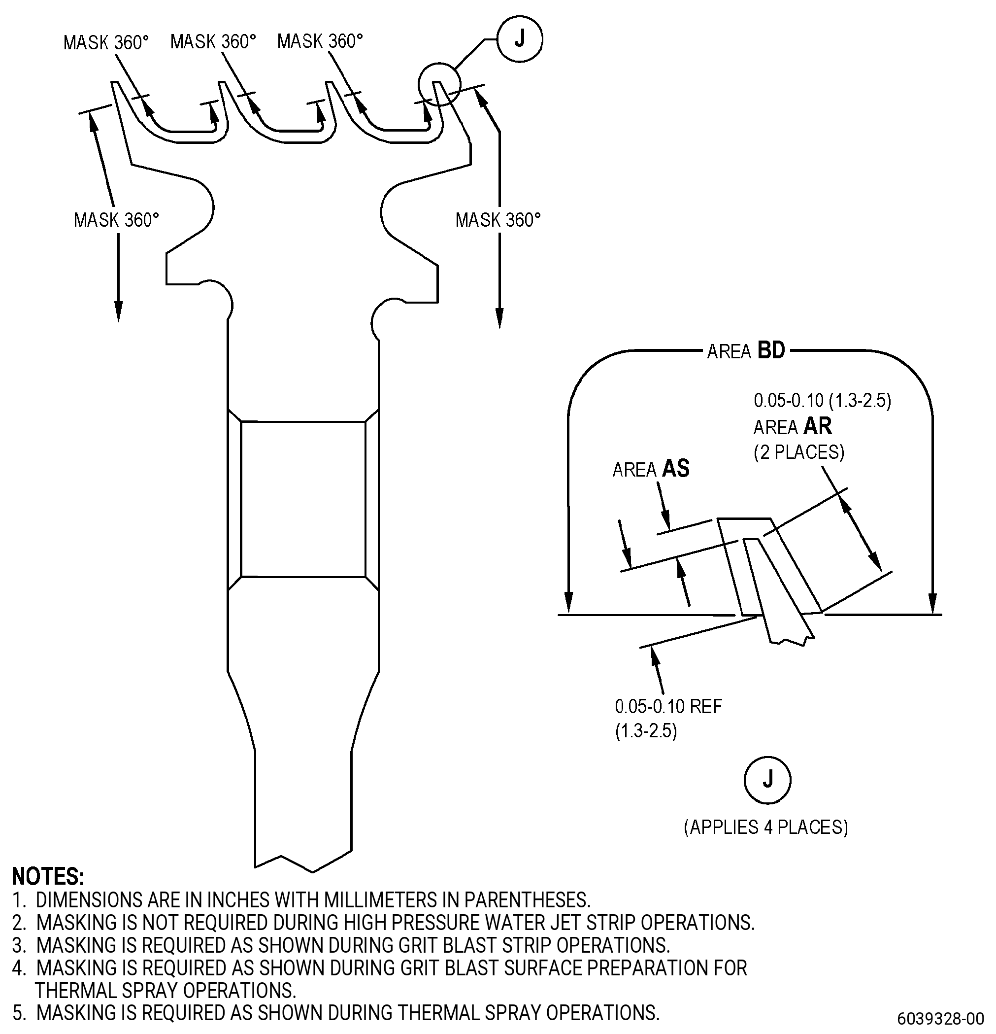
| (2) | Apply a mask to the part. Refer to Figure 904 and as follows: |
| (a) | Use C10-012 tape or hard mask. |
| (3) | Do a grit blast to area BD. Refer to TASK 70-49-00-340-001 (THERMAL SPRAYING) and Figure 904. |
| (4) | Do a solvent clean of area BD. Refer to TASK 70-49-00-340-001 (THERMAL SPRAYING) and Figure 904. |
| Subtask 72-31-46-340-002 |
| J. | Thermal-spray the seal. Refer to TASK 70-49-00-340-001 (THERMAL SPRAYING), TASK 70-49-35-340-037 (THERMAL BARRIER COATING SYSTEM - YTTRIUM OXIDE STABILIZED ZIRCONIUM OXIDE (8% YTTRIUM OXIDE) OVER NICKEL CHROMIUM ALUMINUM YTTRIUM BONDCOAT), Figure 904, and as follows: |
| NOTE: |
|
| (1) | Apply the bond coating to the coupons and tensile bond buttons for testing. |
| (2) | Apply the bond coat to areas AR and AS on each seal tooth as follows: |
| NOTE: |
|
| (a) | Use C07-032 nickel chromium aluminum yttrium powder. |
| (b) | No overspray is permitted. |
| (c) | The thickness of the bond coat in area AS must be 0.002-0.005 inch (0.06-0.12 mm). |
| (d) | The thickness of the bond coat in area AR must be 0.0015-0.0080 inch (0.039-0.203 mm). |
| Subtask 72-31-46-340-003 |
| K. | Thermal-spray the seal. Refer to TASK 70-49-00-340-001 (THERMAL SPRAYING), TASK 70-49-02-340-003 (THERMAL SPRAYING ALUMINUM OXIDE - ALUMINA (POWDER)), Figure 904, and as follows: |
| (1) | Apply the top coating to the coupons and tensile bond buttons for testing. |
| (2) | Apply the top coat to the areas AR and AS on each seal tooth as follows: |
| (a) | Use C07-003 aluminum oxide powder. |
| (b) | No overspray is permitted. |
| (c) | The thickness of the topcoat must be 0.003-0.013 inch (0.08-0.33 mm). |
| (3) | Remove the mask. |
| Subtask 72-31-46-340-004 |
| L. | Do the quality assurance tests. Refer to TASK 70-49-02-340-003 (THERMAL SPRAYING ALUMINUM OXIDE - ALUMINA (POWDER)), and TASK 70-49-35-340-037 (THERMAL BARRIER COATING SYSTEM - YTTRIUM OXIDE STABILIZED ZIRCONIUM OXIDE (8% YTTRIUM OXIDE) OVER NICKEL CHROMIUM ALUMINUM YTTRIUM BONDCOAT), except as follows: |
| (1) | The porosity for the top coat must be less than or equal to V-4. |
| Subtask 72-31-46-320-003 |
| M. | Machine the seal. Refer to TASK 70-00-03-800-004 (MACHINING DATA), Subtask 72-31-46-220-030 (paragraph 3.A.), Dimensional Information and as follows: |
| (1) | Set-up the seal in the machining fixture. Refer to Subtask 72-31-46-930-002 (paragraph 4.C.), Setup Information, Subtask 72-31-46-350-005 (paragraph 4.D.), Setup Information, and Figure 903. |
| (2) | Machine diameter AP to the finish dimension. Refer to Subtask 72-31-46-220-030 (paragraph 3.A.), Dimensional Information, Figure 901, and as follows: |
| (a) | The minimum topcoat thickness in area AS must be 0.003 inch (0.08 mm). |
| Subtask 72-31-46-100-002 |
| N. | Clean the seal. Refer to TASK 70-21-00-110-051 (CHEMICAL CLEANING) and TASK 70-21-03-160-001 (CLEANING METHOD 3 - STEAM CLEANING). |
| Subtask 72-31-46-220-037 |
| O. | Do a visual inspection of the machined coating on the seal teeth. Refer to TASK 72-31-46-200-801 (72-31-46, INSPECTION 001). |