| GENX-1B CLEANING,INSPECTION,AND REPAIR MANUAL | Dated: 03/04/2021 | |
| CIR 72-53-44 , REPAIR 002 | ||
| HIGH PRESSURE TURBINE ROTOR AFT SEAL - REPAIR - OUTER SEAL TEETH THERMAL SPRAY REPAIR | ||
| GENX-1B CLEANING,INSPECTION,AND REPAIR MANUAL | Dated: 03/04/2021 | |
| CIR 72-53-44 , REPAIR 002 | ||
| HIGH PRESSURE TURBINE ROTOR AFT SEAL - REPAIR - OUTER SEAL TEETH THERMAL SPRAY REPAIR | ||
| * * * FOR ALL |
| TASK 72-53-44-300-802 |
| 1 . | Repair for the High Pressure Turbine Rotor Aft Seal. |
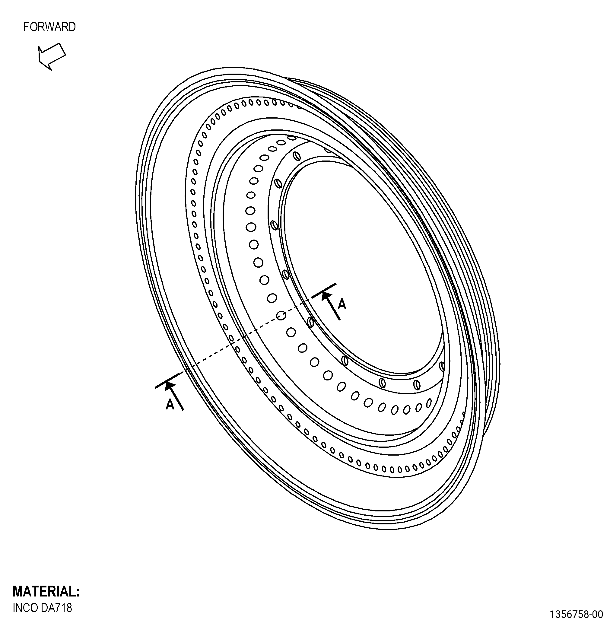
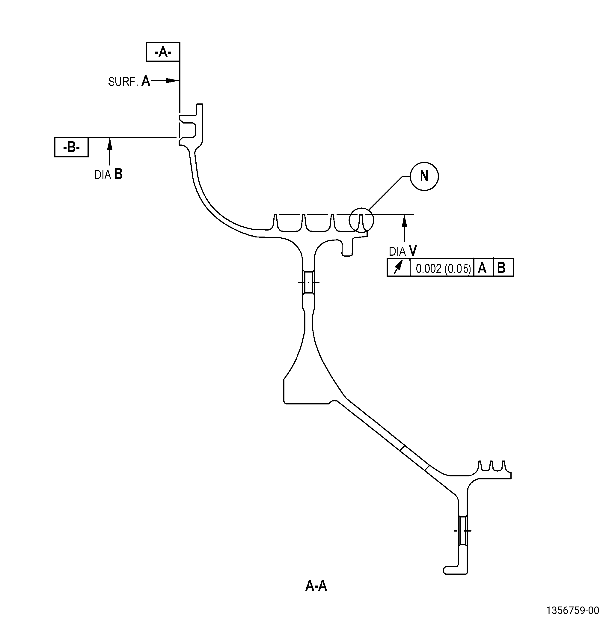
| A. | This procedure gives instructions to repair worn or damaged coating on the high pressure turbine rotor outer seal teeth (seal teeth) with a thermal spray repair. Refer to Figure 901. |
| B. | The following Maximum Repairable limits apply to this repair: |
| NOTE: |
|
| NOTE: |
|
| (4) | Visual Inspection. |
| (h) | Do an inspection of outer seal serrations for: |
| 4 | Worn coating: |
| Maximum repairable limit: |
|
| (5) | Dimensional Inspection. |
| (c) | Do an inspection of the aft seal for: |
| 1 | Diameter V (V1, V2, V3, V4): |
| Maximum repairable limit: |
|
| C. | The subsequent table gives a list of the part numbers that are applicable to this repair. All part numbers are applicable to all paragraphs unless specified differently. |
|
|||||||||||||||||||||||
| D. | Proprietary/Complex Process Statement. |
| (1) | None. |
| 2 . | Tools, Equipment, and Materials. |
| NOTE: |
|
| A. | Tools and Equipment. |
| (1) | Special Tools. None. |
| (2) | Standard Tools and Equipment. None. |
| (3) | Locally Manufactured Tools. None. |
| B. | Consumable Materials. |
| C. | Referenced Procedures. |
|
| D. | Expendable Parts. None. |
| E. | SPD Information. None. |
| F. | Special Solutions. None. |
| G. | Test Specimens. Refer to TASK 70-49-02-340-003 (THERMAL SPRAYING ALUMINUM OXIDE - ALUMINA (POWDER)) and TASK 70-49-10-340-011 (THERMAL SPRAYING NICKEL-ALUMINUM (POWDER)) . |
| 3 . | Dimensional Information. |
| Subtask 72-53-44-220-044 |
| A. | Refer to Figure 901 for specified dimensions and locations. |
| NOTE: |
|
|
| 4 . | Setup Information. |
| Subtask 72-53-44-350-005 |
| A. | Optional Procedure. Set-up the high pressure turbine rotor aft seal (seal) for cleaning or coating as follows: |
| (1) | Surface A must be flat to 0.050 inch (1.27 mm) or less. |
| (2) | Diameter B must have a runout of 0.050 inch (1.27 mm) or less. |
| Subtask 72-53-44-350-006 |
| B. | Set up the high pressure turbine rotor aft seal (seal) for machining as follows: |
| (1) | Surface A must be flat to 0.002 inch (0.05 mm) or less. |
| (2) | Diameter B must have a runout of 0.002 inch (0.05 mm) or less. |
| 5 . | Procedure. |
| Subtask 72-53-44-330-002 |
| CAUTION: |
|
| A. | Alternative Procedure Available. Remove the thermal spray coating from the seal teeth. Refer to TASK 70-23-00-100-001 (STRIPPING PROCEDURES), TASK 70-23-23-330-008 (REMOVAL OF COATINGS BY HIGH PRESSURE WATER STRIPPING), and as follows: |
| (1) | Set up the seal. Refer to Subtask 72-53-44-350-005 (paragraph 4.A.), Setup Information. |
| (2) | Remove the thermal spray coating from the seal teeth. |
| Subtask 72-53-44-350-007 |
| A.A. | Alternative Procedure. Remove the coating from the seal teeth as follows: |
| (1) | Set up the seal in the holding fixture. Refer to Figure 901 and Subtask 72-53-44-350-005 (paragraph 4.A.), Setup Information. |
| (2) | Apply a mask to the part. Refer to Figure 902 and as follows: |
| (a) | Use C10-021 plastic tape. |
| Subtask 72-53-44-120-002 |
| (3) | Clean the coated area of the seal teeth. Refer to TASK 70-21-04-120-001 (CLEANING METHOD NO. 4 - DRY ABRASIVE BLAST CLEANING) and as follows: |
| (a) | Use Method 4A. |
| (b) | Use C04-113 220 mesh abrasive grit. |
| (c) | Remove the top coat only. |
| Subtask 72-53-44-100-002 |
| (4) | Remove the C10-021 plastic tape. |
| (5) | Remove the bond coating. Refer to TASK 70-23-00-100-001 (STRIPPING PROCEDURES) and TASK 70-23-12-110-027 (STRIPPING THERMAL SPRAYED COATINGS). |
| (6) | Deleted. |
| Subtask 72-53-44-220-045 |
| B. | Do a dimensional inspection of the seal teeth in-process dimension. Refer to Subtask 72-53-44-220-044 (paragraph 3.A.), Dimensional Information, and as follows: |
| Subtask 72-53-44-320-001 |
| (1) | If necessary, machine the seal teeth. Refer to TASK 70-00-03-800-004 (MACHINING DATA) and as follows: |
| (a) | Set up the seal for machining. Refer to Subtask 72-53-44-350-006 (paragraph 4.B.), Setup Information. |
| (b) | Machine the seal teeth to remove the damage and to make the part agree with the in-process dimensions. |
| Subtask 72-53-44-350-008 |
| C. | Blend the burrs and rolled edges from the seal teeth. Refer to TASK 70-42-00-350-002 (BLENDING AND REMOVAL OF HIGH METAL PROCEDURES), and as follows: |
| (1) | Break the edges to 0.005 inch (0.12 mm) maximum. |
| Subtask 72-53-44-160-003 |
| D. | Clean the seal. Refer to TASK 70-21-03-160-001 (CLEANING METHOD NO. 3 - STEAM CLEANING). |
| Subtask 72-53-44-110-005 |
| E. | Etch the seal teeth. Refer to TASK 70-24-00-110-033 (ETCHING PROCEDURES FOR FLUORESCENT-PENETRANT INSPECTION), TASK 70-24-01-110-034 (SWAB ETCHING PROCEDURE), and as follows: |
| (1) | Use Class C or Class G etchant. |
| Subtask 72-53-44-200-003 |
| F. | Alternative Procedure Available. Do an inspection of the seal teeth. Refer to TASK 70-32-00-200-002 (INDIRECT INSPECTION METHODS), TASK 70-32-02-230-001 (FLUORESCENT PENETRANT INSPECTION), and as follows: |
| (1) | Use Class G penetrant. |
| (2) | Refer to TASK 72-53-44-200-801 (72-53-44, INSPECTION 001) for the fluorescent-penetrant inspection limits. |
| Subtask 72-53-44-200-004 |
| F.A. | Alternative Procedure. Do an inspection of the seal teeth. Refer to TASK 70-32-00-200-002 (INDIRECT INSPECTION METHODS), TASK 70-32-03-230-002 (SPOT-FLUORESCENT-PENETRANT INSPECTION), and as follows: |
| (1) | Use Class G penetrant. |
| (2) | Refer to TASK 72-53-44-200-801 (72-53-44, INSPECTION 001) for the fluorescent-penetrant inspection limits. |
| Subtask 72-53-44-380-002 |
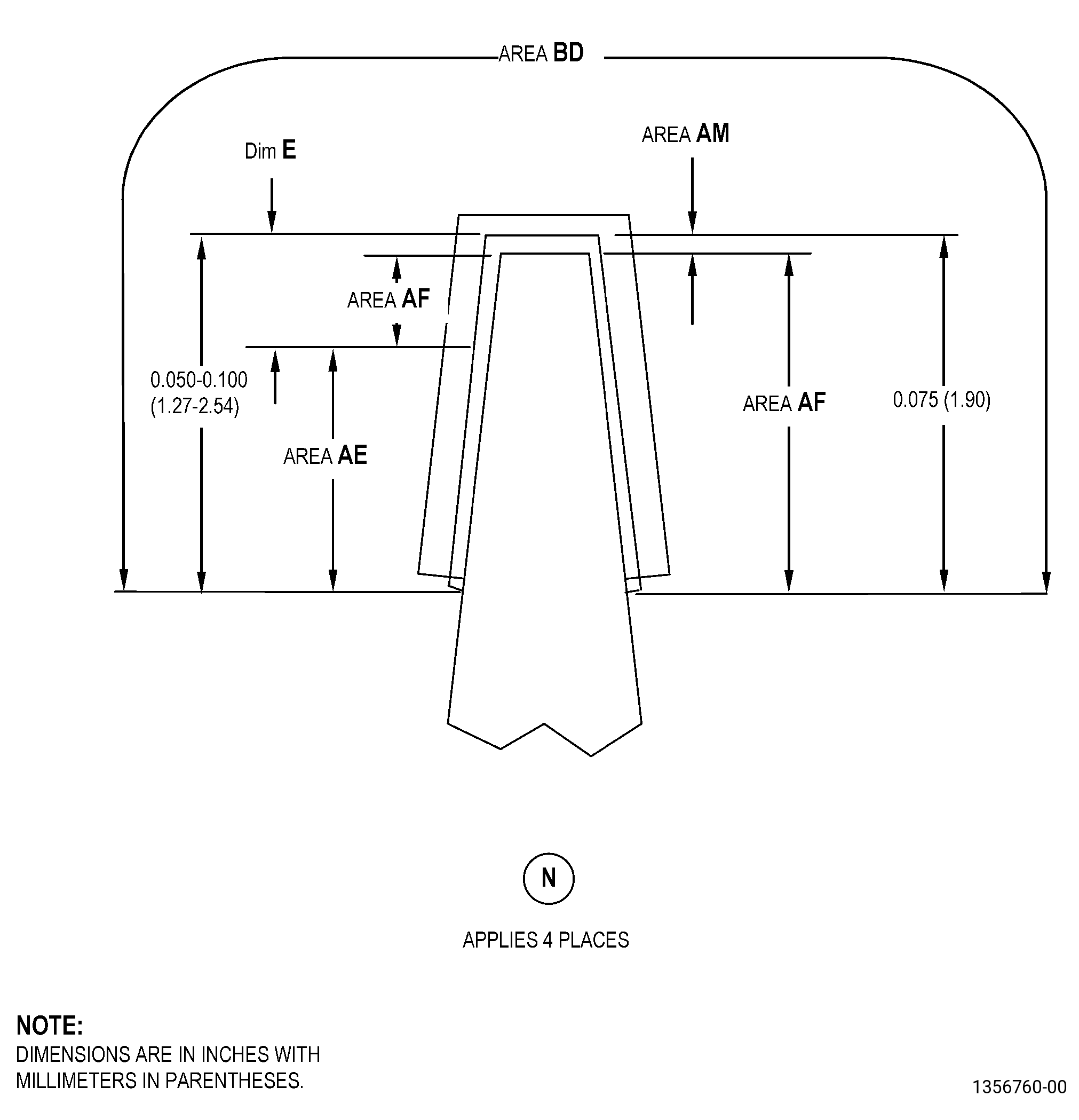
| G. | Peen area BD of the seal. Refer to TASK 70-47-01-380-016 (SHOTPEENING), Figure 901, and as follows: |
| (1) | Set up the seal. Refer to Subtask 72-53-44-350-005 (paragraph 4.A.), Setup Information. |
| (2) | Deleted. |
| (3) | Use C04-286 S110 steel shot. |
| (4) | Peen to an intensity of 0.006-0.012 N. |
| (5) | Overspray is permitted. |
| Subtask 72-53-44-340-001 |
| H. | Thermal spray the seal teeth and the test specimens. Refer to TASK 70-49-00-340-001 (THERMAL SPRAYING), TASK 70-49-10-340-011 (THERMAL SPRAYING NICKEL-ALUMINUM (POWDER)), Subtask 72-53-44-220-044 (paragraph 3.A.), Dimensional Information, Figure 901, and as follows: |
| (1) | Apply C10-012 masking tape to all areas that you will not thermal spray. Refer to Figure 902. |
| Subtask 72-53-44-350-009 |
| (2) | Set up the seal. Refer to Subtask 72-53-44-350-005 (paragraph 4.A.), Setup Information. |
| Subtask 72-53-44-340-002 |
| (3) | Do the preliminary operations specified in TASK 70-49-00-340-001 (THERMAL SPRAYING). |
| (a) | Use the surface roughness limits for the nickel base material. |
| (4) | Apply a bond coating of C07-016 nickel-aluminum composite powder to the seal teeth and the test specimens as follows: |
| (a) | Overspray is not permitted. |
| (b) | The thickness must be 0.002-0.005 inch (0.06-0.12 mm) in area AM. |
| (c) | The thickness must be 0.0015-0.0050 inch (0.039-0.127 mm) in area AF. |
| (d) | Make sure that the thermal spray coating that you applied to the test specimens simulates the part geometry, the spray angle, and the sprayed deposit thickness that you applied to the seal teeth. |
| Subtask 72-53-44-340-003 |
| (5) | Do all the quality assurance testing specified in TASK 70-49-10-340-011 (THERMAL SPRAYING NICKEL-ALUMINUM (POWDER)), refer to Figure 901 and as follows: |
| (a) | Thickness and coverage requirements in area AE do not apply except bond coat is required under 80 percent of top coat. |
| Subtask 72-53-44-340-004 |
| I. | Thermal spray the seal and the test specimens. Refer to TASK 70-49-00-340-001 (THERMAL SPRAYING), TASK 70-49-02-340-003 (THERMAL SPRAYING ALUMINUM OXIDE - ALUMINA (POWDER)), Subtask 72-53-44-220-044 (paragraph 3.A.), Dimensional Information, and as follows: |
| (1) | Apply a top coating of C07-003 aluminum oxide powder to the seal teeth and the test specimens as follows: |
| (a) | Overspray is not permitted. |
| (b) | The final thickness after machining must be 0.003-0.013 inch (0.08-0.33 mm) in area AM. |
| (c) | The final thickness after machining must be 0.003-0.013 inch (0.08-0.33 mm) in area AF. |
| (d) | Make sure that the thermal spray coating that you applied to the test specimens simulates the part geometry, the spray angle, and the sprayed deposit thickness that you applied to the seal teeth. |
| Subtask 72-53-44-340-005 |
| (2) | Do all the quality assurance testing specified in TASK 70-49-02-340-003 (THERMAL SPRAYING ALUMINUM OXIDE - ALUMINA (POWDER)), refer to Figure 901, and as follows: |
| (a) | Thickness and coverage requirements in area AE do not apply except bond coat is required under 80 percent of top coat. |
| (3) | Remove the C10-012 masking tape. |
| Subtask 72-53-44-320-002 |
| J. | Machine the seal. Refer to TASK 70-00-03-800-004 (MACHINING DATA), Subtask 72-53-44-220-044 (paragraph 3.A.), Dimensional Information, Figure 901, and as follows: |
| (1) | Set up the seal for machining. Refer to Subtask 72-53-44-350-006 (paragraph 4.B.), Setup Information. |
| (2) | Machine diameter V to the finish dimensions. |
| (3) | Verify the top coating thickness is 0.003 inch (0.08 mm) minimum. |
| Subtask 72-53-44-220-046 |
| K. | Do a visual inspection of thermal spray coating for spalling, chipping, cracking, or separation. Refer to TASK 72-53-44-200-801 (72-53-44, INSPECTION 001). |
| Subtask 72-53-44-200-005 |
| L. | Do a dimensional inspection of diameter V. Refer to TASK 72-53-44-200-801 (72-53-44, INSPECTION 001). |