| GENX-1B CLEANING,INSPECTION,AND REPAIR MANUAL | Dated: 12/27/2022 | |
| CIR 72-31-44, REPAIR 004 | ||
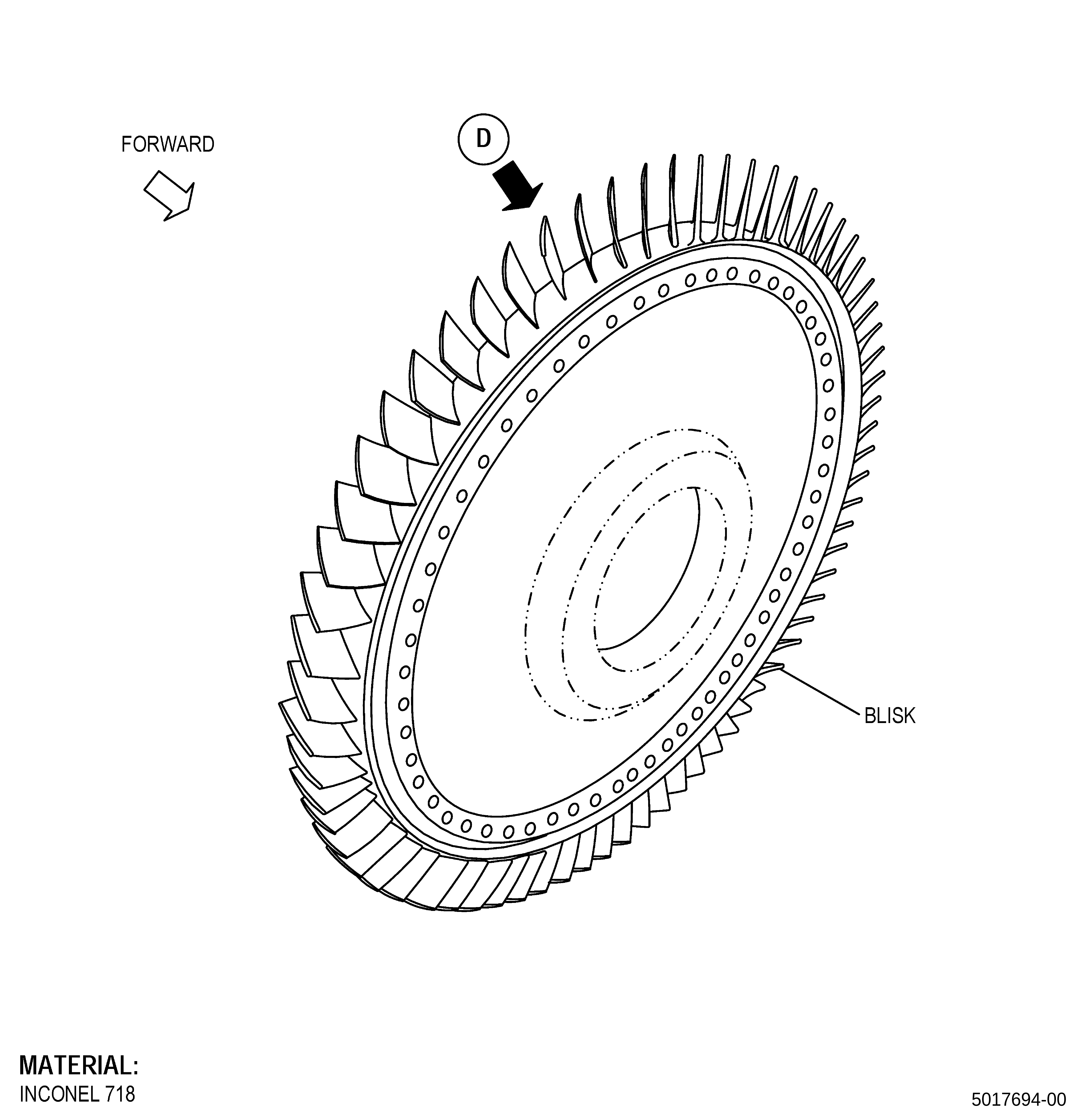
| HIGH PRESSURE COMPRESSOR ROTOR STAGE 5 BLISK - REPAIR - THERMAL SPRAY REPAIR OF THE FORWARD RABBET AND AFT RABBET | ||
| GENX-1B CLEANING,INSPECTION,AND REPAIR MANUAL | Dated: 12/27/2022 | |
| CIR 72-31-44, REPAIR 004 | ||
| HIGH PRESSURE COMPRESSOR ROTOR STAGE 5 BLISK - REPAIR - THERMAL SPRAY REPAIR OF THE FORWARD RABBET AND AFT RABBET | ||
| * * * FOR ALL |
| TASK 72-31-44-300-803 |
| 1. | Thermal Spray Repair of the Forward Rabbet and Aft Rabbet. |
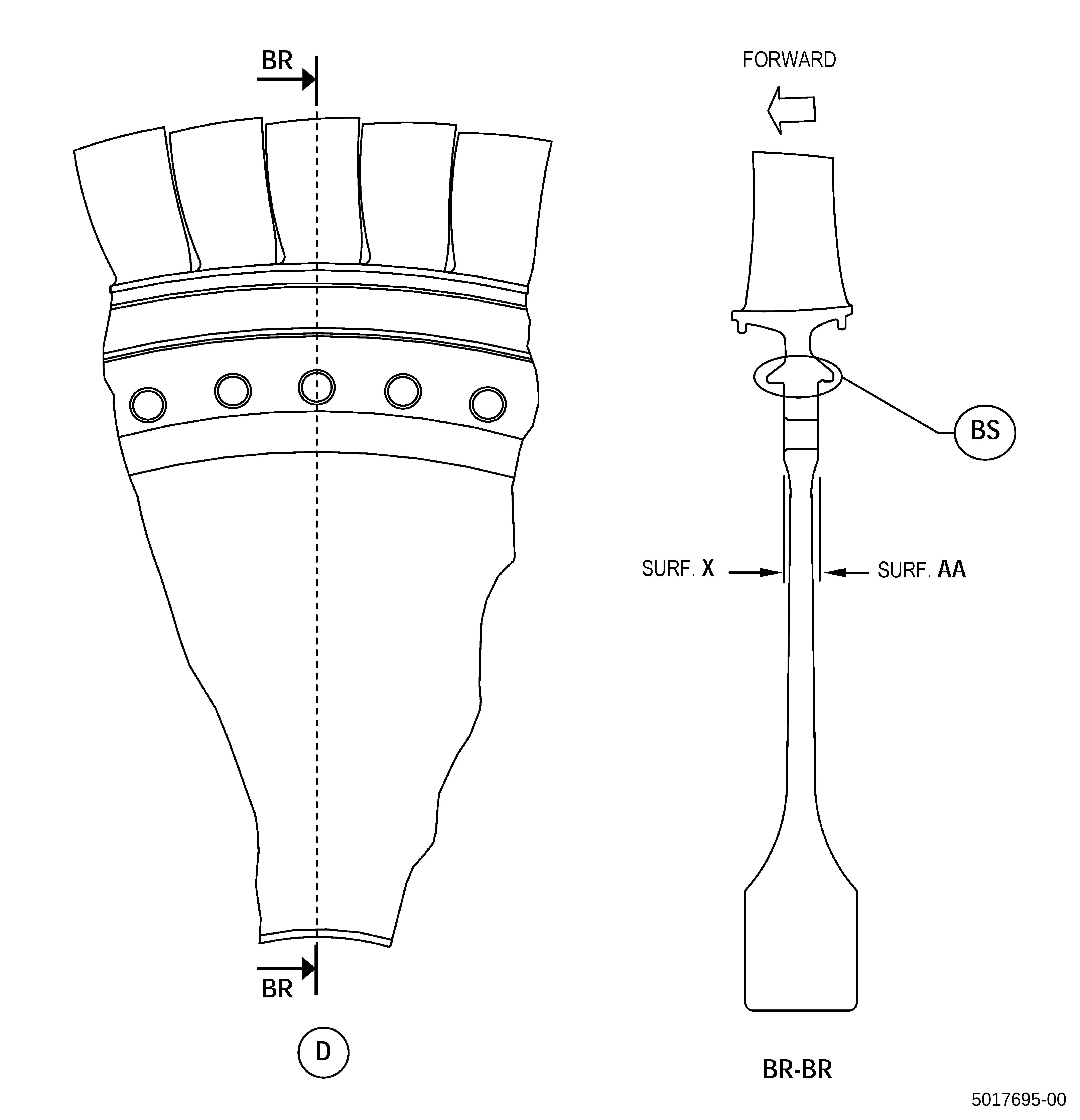
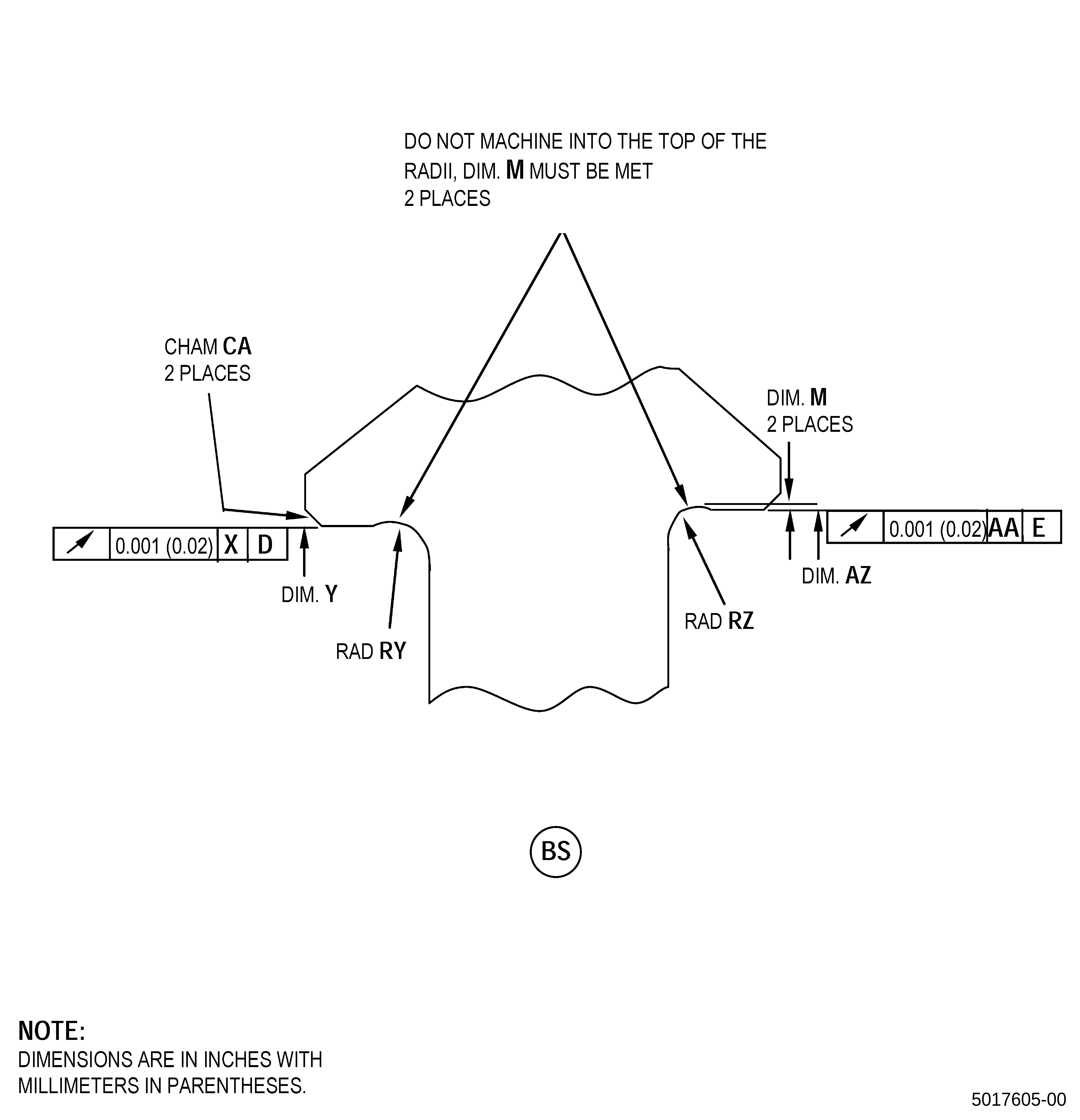
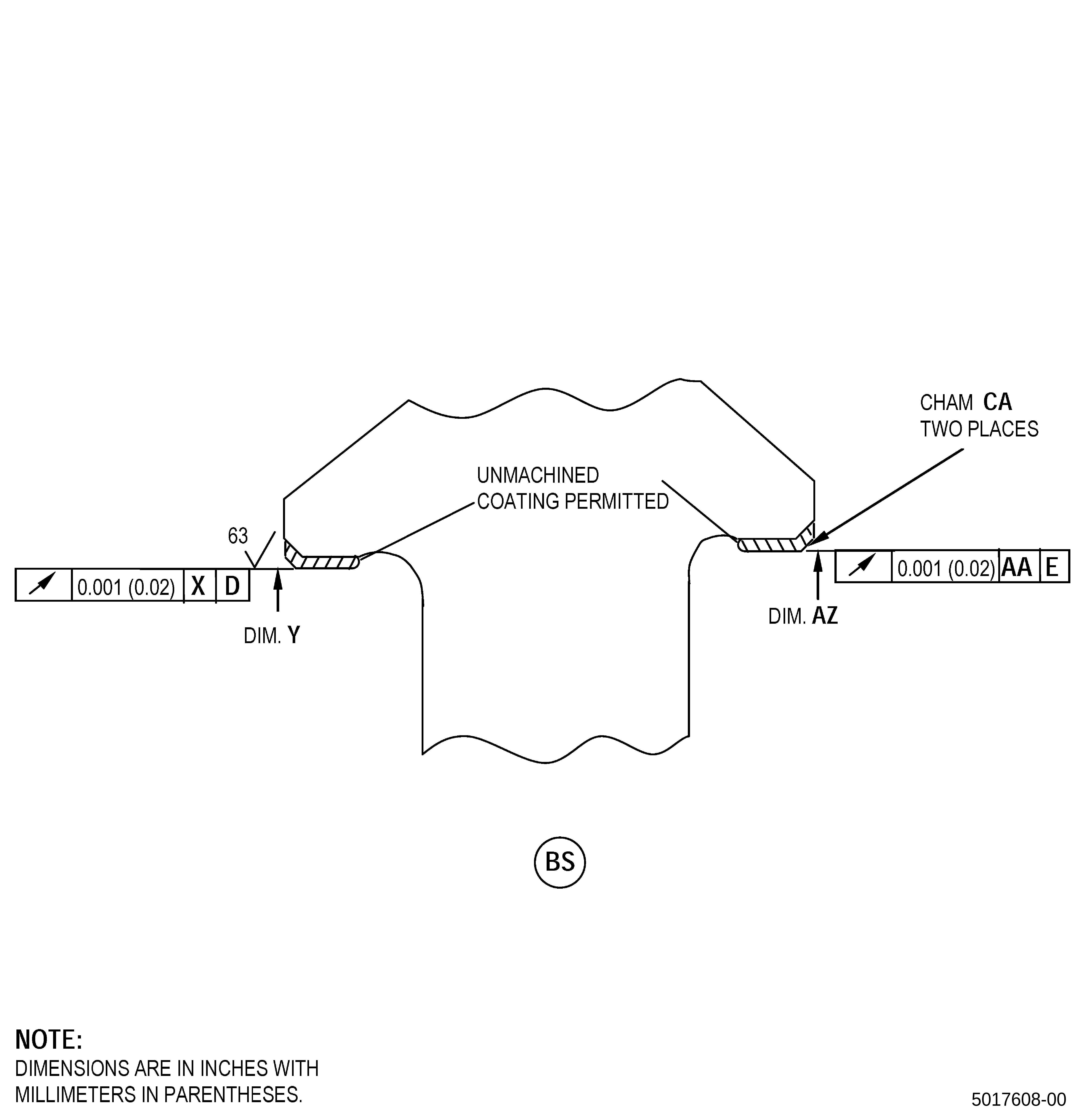
| A. | This procedure gives instructions to repair the high pressure compressor rotor stage 5 blisk (blisk) by thermal spraying the forward rabbet (diameter Y) and aft rabbet (diameter AZ). Refer to Figure 901. |
| NOTE: |
|
| B. | The following maximum repairable limits apply to this repair: |
| NOTE: |
|
| NOTE: |
|
| (5) | Visual Inspection. |
| (l) | Do an inspection of the forward rabbet and aft rabbet for: |
| 1 | Fretting and galling on parent material: |
| Maximum repairable limit: |
|
| 2 | Chipped or missing coating: |
| Maximum repairable limit: |
|
| (6) | Special Dimensional Inspection. |
| (c) | Measure the dimensions that follow: |
| 4 | Diameter Y: |
| Maximum repairable limit: |
|
| 5 | Diameter AZ: |
| Maximum repairable limit: |
|
| C. | The subsequent table gives a list of the part numbers that are applicable to this repair. All part numbers are applicable to all paragraphs unless specified differently. |
|
|||||||||||||||||||||||
| D. | Proprietary/Complex Process Statement. |
| (1) | None. |
| 2. | Tools, Equipment, and Materials. |
| NOTE: |
|
| A. | Tools and Equipment. |
| (1) | Special Tools. None. |
| (2) | Standard Tools and Equipment. None. |
| (3) | Locally Manufactured Tools. None. |
| B. | Consumable Materials. |
|
| C. | Referenced Procedures. |
| D. | Expendable Parts. None. |
| E. | SPD Information. |
| (1) | Locally Manufactured SPD. None. |
| F. | Special Solutions. None. |
| G. | Test Specimens. Refer to TASK 70-49-32-340-033 (THERMAL SPRAYING INCONEL 718 (POWDER)) . |
| 3 . | Dimensional Information. |
| Subtask 72-31-44-220-064 |
| A. | Refer to Figure 901, Figure 902, and Figure 904 for specified dimensions and locations. |
| NOTE: |
|
| NOTE: |
|
|
| 4 . | Setup Information. |
| Subtask 72-31-44-350-005 |
| A. | Deleted. |
| Subtask 72-31-44-350-007 |
| B. | Set-up the blisk for machining. Refer to Figure 901 and as follows: |
| (1) | To repair the blisk diameter Y, install the blisk on a holding fixture as follows: |
| (a) | Install the blisk with the forward end up in the machining fixture. |
| (b) | Surface X must be flat to 0.001 inch (0.03 mm) or less. |
| (c) | Diameter Y must have a runout of 0.001 inch (0.03 mm) or less. |
| (2) | To repair the blisk diameter AZ, install the blisk on a holding fixture as follows: |
| (a) | Install the blisk with the aft end up in the holding fixture. |
| (b) | Surface AA must be flat to 0.001 inch (0.03 mm) or less. |
| (c) | Diameter AZ must have a runout of 0.001 inch (0.03 mm) or less. |
| 5 . | Procedure. |
| Subtask 72-31-44-160-004 |
| A. | If necessary, clean the blisk. Refer to TASK 72-31-44-100-801 (72-31-44, CLEANING 001). |
| Subtask 72-31-44-350-008 |
| CAUTION: |
|
| B. | Apply masking to the blisk airfoil area for damage protection as follows: |
| (1) | Use C10-012 masking tape. |
| (2) | Keep this C10-012 masking tape in position until the end of this procedure. |
| Subtask 72-31-44-330-001 |
| C. | If there is thermal spray coating on the blisk diameter Y/diameter AZ, remove the thermal spray coating from the blisk as follows: |
| (1) | If necessary, make a holding fixture to hold the blisk. |
| (2) | Remove the thermal spray coating from the blisk diameter Y/diameter AZ. Refer to TASK 70-23-00-100-001 (STRIPPING PROCEDURES) and TASK 70-23-23-330-008 (REMOVAL OF COATINGS BY HIGH PRESSURE WATER STRIPPING). |
| NOTE: |
|
| (3) | Remove the blisk from the holding fixture. |
| Subtask 72-31-44-320-001 |
| CAUTION: |
|
| D. | Machine the blisk. Refer to TASK 70-00-03-800-004 (MACHINING DATA), Subtask 72-31-44-220-064 (paragraph 3.A.), and as follows: |
| (1) | Make sure that you use the necessary precautions for your protection from the rotating blades during machining. The rotating blades can cause personal injury. |
| (2) | Set-up the blisk for machining. Refer to Subtask 72-31-44-350-007 (paragraph 4.B.). |
| (3) | Machine the blisk diameter Y/diameter AZ to the in-process dimensions and as follows: |
| NOTE: |
|
| (a) | Remove all damage and an additional 0.002 inches (0.05 mm) from the damaged surface. |
| (b) | Dimension M must be equal to or more than 0.002 inch (0.05 mm) after machining to the in-process dimension necessary to remove thermal spray coating and/or to prepare the surface. |
| (4) | If there is thermal spray coating on the blisk diameter Y/diameter AZ, remove all the thermal spray coating from diameter Y/diameter AZ. |
| Subtask 72-31-44-350-010 |
| (5) | If necessary, blend the blisk. Refer to TASK 70-42-00-350-002 (BLENDING AND REMOVAL OF HIGH METAL PROCEDURES) and as follows: |
| (a) | Remove burrs and rolled edges. |
| (b) | Break sharp edges to a maximum of 0.010 inch (0.25 mm). |
| (6) | Remove the minimum necessary quantity of material. |
| (7) | Remove the blisk from the holding fixture. |
| Subtask 72-31-44-160-005 |
| E. | Clean the blisk. Refer to TASK 70-21-00-110-051 (CHEMICAL CLEANING) and TASK 70-21-03-160-001 (CLEANING METHOD NO. 3 - STEAM CLEANING). |
| Subtask 72-31-44-110-010 |
| F. | Etch the blisk diameter Y/diameter AZ. Refer to TASK 70-24-00-110-033 (ETCHING PROCEDURES FOR FLUORESCENT-PENETRANT INSPECTION), TASK 70-24-01-110-034 (SWAB ETCHING PROCEDURE), and as follows: |
| (1) | Use Class C etchant. |
| Subtask 72-31-44-230-005 |
| G. | Do an inspection of the blisk diameter Y/diameter AZ. Refer to TASK 70-32-00-200-002 (INDIRECT INSPECTION METHODS), TASK 70-32-03-230-002 (SPOT-FLUORESCENT-PENETRANT INSPECTION), and as follows: |
| (1) | Use Class G penetrant. |
| (2) | Refer to TASK 72-31-44-200-801 (72-31-44, INSPECTION 001) for the acceptability limits. |
| Subtask 72-31-44-380-051 |
| H. | Peen the blisk diameter Y/diameter AZ. Refer to TASK 70-47-01-380-016 (SHOTPEENING) and as follows: |
| (1) | If necessary, make a holding fixture to hold the blisk. |
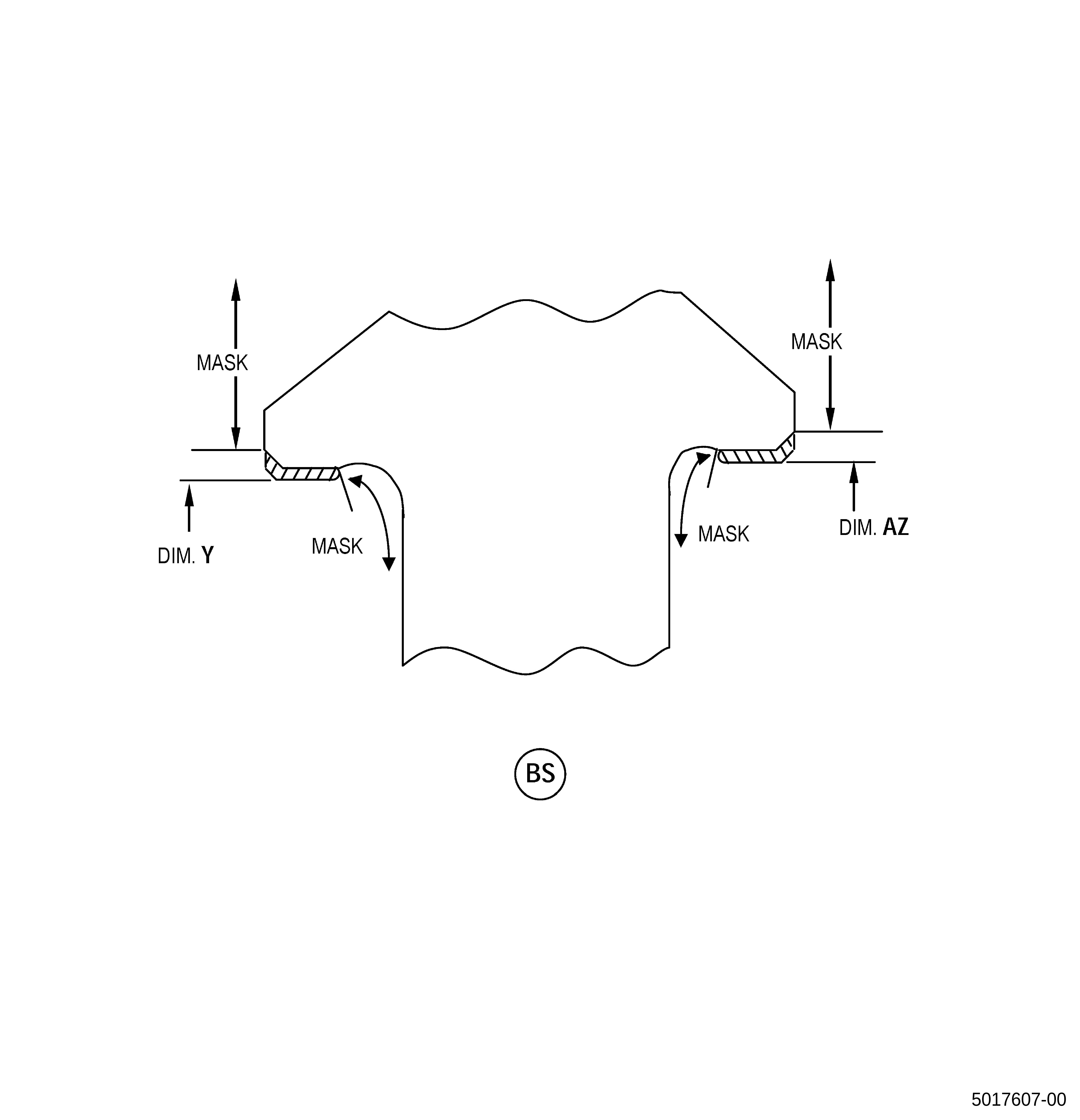
| (2) | Apply C10-021 plastic tape to all the blisk areas that you will not peen. Refer to Figure 903. |
| (3) | Use C04-286 S110 cast steel shot. |
| (4) | Peen the blisk to an intensity of 0.006-0.012N. |
| (5) | Coverage must be a minimum of 125 percent, not more than 200 percent. |
| (6) | Intensity verification is necessary in the blisk repaired area. Use a scrap part or simulative fixture. |
| (7) | Remove the plastic tape from the blisk. |
| (8) | Remove the blisk from the holding fixture. |
| Subtask 72-31-44-340-001 |
| I. | Thermal-spray the blisk and test specimens. Refer to TASK 70-49-00-340-001 (THERMAL SPRAYING), TASK 70-49-32-340-033 (THERMAL SPRAYING INCONEL 718 (POWDER)), Subtask 72-31-44-220-064 (paragraph 3.A.), and as follows: |
| NOTE: |
|
| (1) | Apply C10-012 masking tape to all the blisk areas that you will not thermal-spray. Refer to Figure 903. |
| (2) | If necessary, make a holding fixture to hold the blisk. |
| (3) | Do the preliminary operations specified in TASK 70-49-00-340-001 (THERMAL SPRAYING) and as follows: |
| (a) | Use the surface roughness limits for the nickel base material. |
| (4) | Thermal-spray the blisk diameter Y/diameter AZ and the test specimens. Make sure that you apply thermal spray coating to the test specimens at the same time and to the same thickness as the blisk diameter Y/diameter AZ and as follows: |
| (a) | Overspray is not permitted. |
| (b) | Apply a sufficient quantity of thermal spray coating to permit machining of the blisk diameter Y/diameter AZ to the finish dimensions. |
| 1 | Maximum as sprayed thickness for coating is 0.040 inch (1.01 mm). |
| (c) | The final thermal spray coating thickness after finish machining must be a minimum of 0.004 inch (0.11 mm). |
| (d) | The thermal spray coating applied to the test specimens must simulate the part geometry, the spray angle, and the as-sprayed deposit thickness on the blisk. |
| (5) | Do all the quality assurance testing specified in TASK 70-49-32-340-033 (THERMAL SPRAYING INCONEL 718 (POWDER)). |
| (6) | Remove the masking tape from the blisk. |
| (7) | Remove the blisk from the holding fixture. |
| Subtask 72-31-44-320-002 |
| J. | Machine the blisk. Refer to TASK 70-00-03-800-004 (MACHINING DATA), Subtask 72-31-44-220-064 (paragraph 3.A.), Figure 904, and as follows: |
| (1) | Make sure that you use the necessary precautions for your protection from the rotating blades during machining. The rotating blades can cause personal injury. |
| (2) | Set-up the blisk for machining. Refer to Subtask 72-31-44-350-007 (paragraph 4.B.). |
| (3) | Machine the blisk diameter Y/diameter AZ and chamfers to the finish dimensions. |
| (4) | The surface finish of the blisk diameter Y/diameter AZ must be 63 microinches (1.6 micrometers) or less. |
| (5) | Remove the blisk from the holding fixture. |
| Subtask 72-31-44-220-065 |
| K. | Do a dimensional inspection of the blisk diameter Y/diameter AZ. Refer to Subtask 72-31-44-220-064 (paragraph 3.A.), Figure 901, and as follows: |
| (1) | If the thermal spray coating thickness on the blisk is less than the requirement or the blisk diameter Y/diameter AZ is less than the minimum finish dimensions, remove and apply the thermal spray coating again. Refer to Subtask 72-31-44-330-001 (paragraph 5.C.) thru Subtask 72-31-44-220-065 (paragraph 5.K.). |
| Subtask 72-31-44-350-009 |
| L. | Remove the masking from the blisk airfoils. |
| Subtask 72-31-44-160-006 |
| M. | Clean the blisk. Refer to TASK 70-21-00-110-051 (CHEMICAL CLEANING) and TASK 70-21-03-160-001 (CLEANING METHOD NO. 3 - STEAM CLEANING). |
| Subtask 72-31-44-220-066 |
| N. | Do a visual inspection of the blisk thermal spray coating as follows: |
| (1) | Spalling, chipping, cracking, or separation of the blisk thermal spray coating is not permitted. |