| GENX-1B ENGINE MANUAL | Dated: 11/24/2023 | |
| EM 72-26-00 , ASSEMBLY 001 | ||
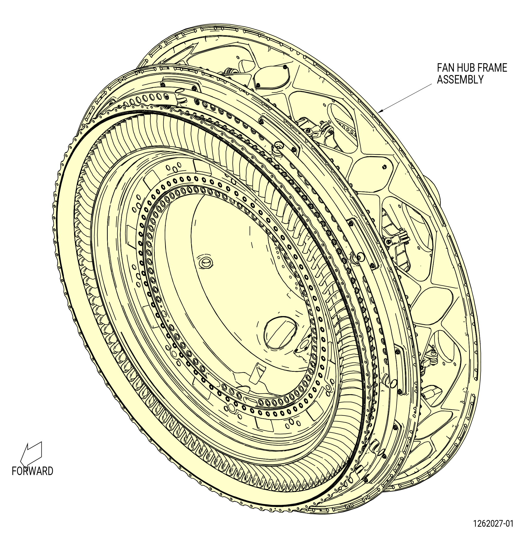
| FAN HUB FRAME ASSEMBLY - ASSEMBLY 001 | ||
| GENX-1B ENGINE MANUAL | Dated: 11/24/2023 | |
| EM 72-26-00 , ASSEMBLY 001 | ||
| FAN HUB FRAME ASSEMBLY - ASSEMBLY 001 | ||
| * * * FOR ALL |
| TASK 72-26-00-440-802 |
| 1 . | General. |
| A. | This procedure gives instructions to assemble the fan hub frame assembly. Refer to Figure 1001. |
| • |
|
| • |
|
| • |
|
| The fan hub frame assembly contains: |
| • |
|
| • |
|
| • |
|
| • |
|
| B. | All clock positions are aft looking forward (ALF), unless specified differently. |
| C. | Protective covers will be installed on spare assemblies only. |
| D. | Make sure that you install new preformed packings. You cannot use preformed packings again. |
| E. | Install all the bolts with the heads up and/or forward unless specific instructions are given. |
| F. | Apply lubricants to threads and friction surfaces only. |
| 2 . | Tools, Equipment, and Materials. |
| NOTE: |
|
| A. | Tools and Equipment. |
| (1) | Special Tools. |
| (2) | Standard Tools and Equipment. None. |
| (3) | Locally Manufactured Tools. None. |
| B. | Consumable Materials. |
|
| C. | Referenced Procedures. |
|
| D. | Expendable Parts. |
|
| 3 . | Procedure. |
| Subtask 72-26-00-440-134 |
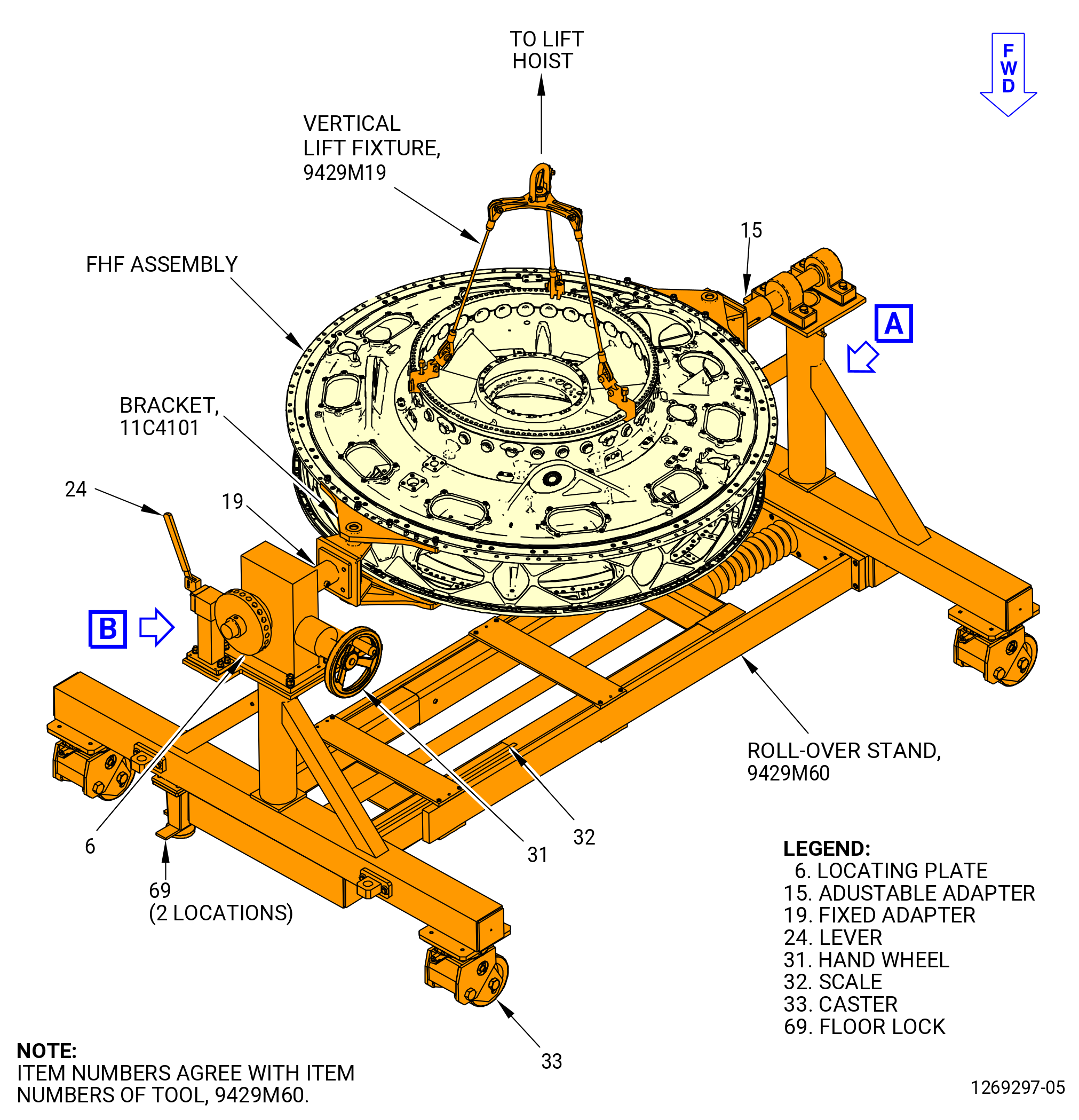
| A. | Install the fan hub frame (FHF), aft side up, on the 9429M60 roll-over stand or 11C4100 roll-over stand as follows: |
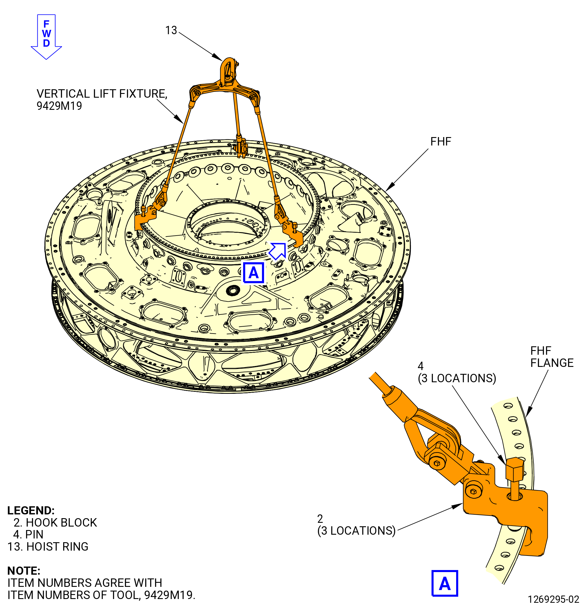
| (1) | Attach the 9429M19 vertical lift fixture to the FHF aft flange as follows. Refer to Figure 1002. |
| (a) | Retract the pins (item 4) and move the hook blocks (item 2) over the flange until they align with the three equally spaced holes in the flange. |
| (b) | Tighten the pins (item 4) until the hook blocks are tightly attached to the flange. |
| Subtask 72-26-00-440-135 |
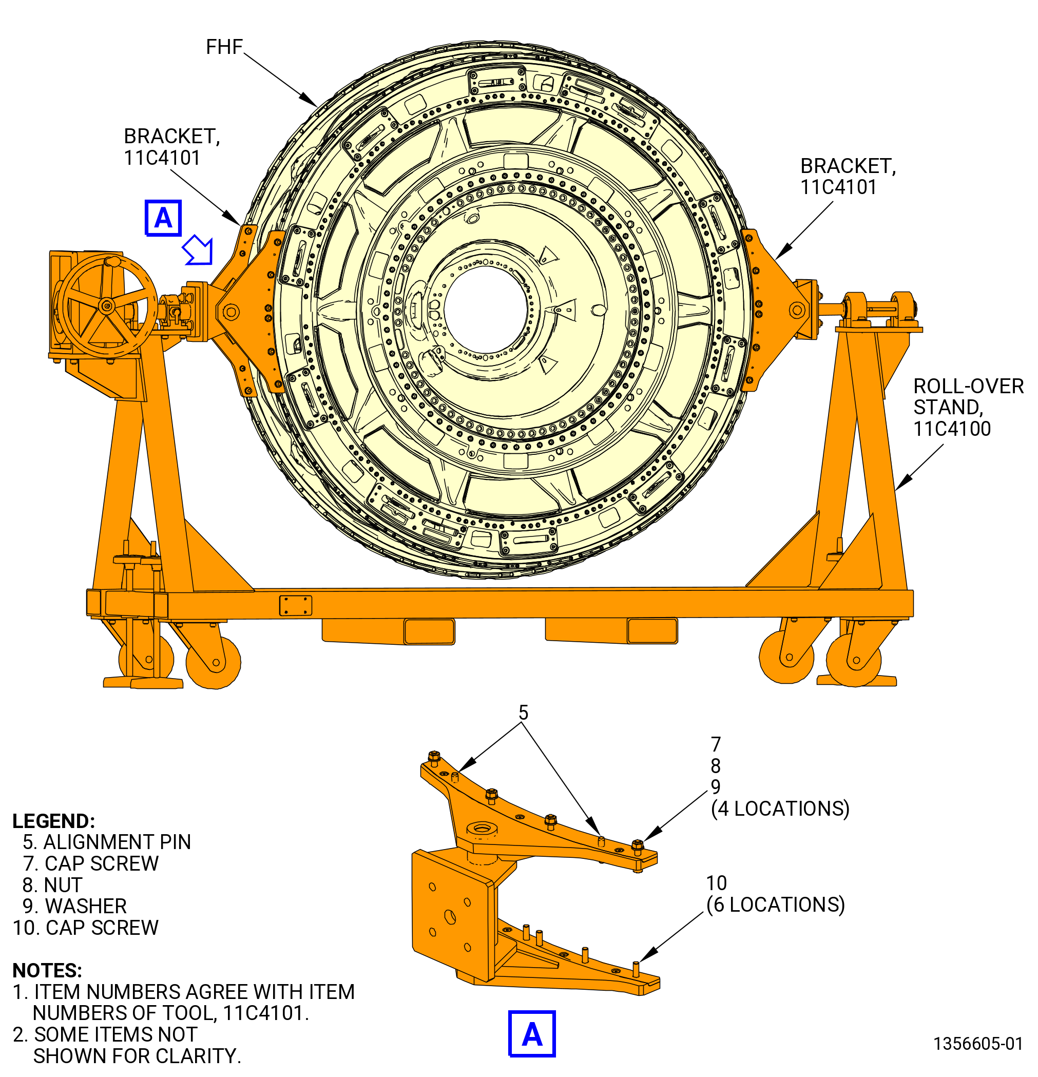
| (2) | Attach the 11C4101 bracket on the FHF at the 3:00 and 9:00 o'clock positions as follows. Refer to Figure 1003. |
| (a) | Put the first bracket on the FHF external flange and verify that the alignment pins (item 5) are respectively put in the boltholes number 21 and 28 clockwise (CW) direction. Count excluding the holes corresponding to the TOP - BOTTOM direction. |
| (b) | Insert four screws (item 7) in the upper surface of the flange. |
| (c) | Insert the four washers (item 9), subsequently insert the four nuts (item 8) and tighten them by hand. |
| (d) | Insert the six screws (item 10) in the lower surface of the flange and tighten them by hand. |
| (e) | Put the second bracket on the FHF external flange and make sure that the alignment pins (item 5) are respectively put in the holes number 21 and 28 counterclockwise (CCW) direction. Count excluding the holes corresponding to the TOP - BOTTOM direction. |
| (f) | Insert four screws (item 7) in the upper surface of the flange. |
| (g) | Insert the four washers (item 9), subsequently insert the four nuts (item 8) and tighten them by hand. |
| (h) | Insert the six screws (item 10) in the lower surface of the flange and tighten them by hand. |
| (i) | Torque the nuts (item 8) and screws (item 10) on both brackets to 190-230 lb in. (21.5-26.0 N.m). |
| Subtask 72-26-00-440-136 |
| CAUTION: |
|
| (3) | Lower the floor locks (item 69) of the 9429M60 roll-over stand until they touch the floor. The floor locks must touch the floor to prevent movement of the assembly stand. Make sure that the 9429M60 roll-over stand is level. Refer to Figure 1005. |
| (4) | Attach an overhead hoist to the hoist ring (item 13) of the 9429M19 vertical lift fixture. Refer to Figure 1002. |
| Subtask 72-26-00-440-158 |
| (5) | Alternative Procedure Available. Install the FHF on the 9429M60 roll-over stand as follows. Refer to Figure 1005. |
| WARNING: |
|
| (a) | Lift the FHF with the 9429M19 vertical lift fixture and overhead hoist. |
| (b) | Carefully lower the fan hub module assembly on the 9429M60 roll-over stand. |
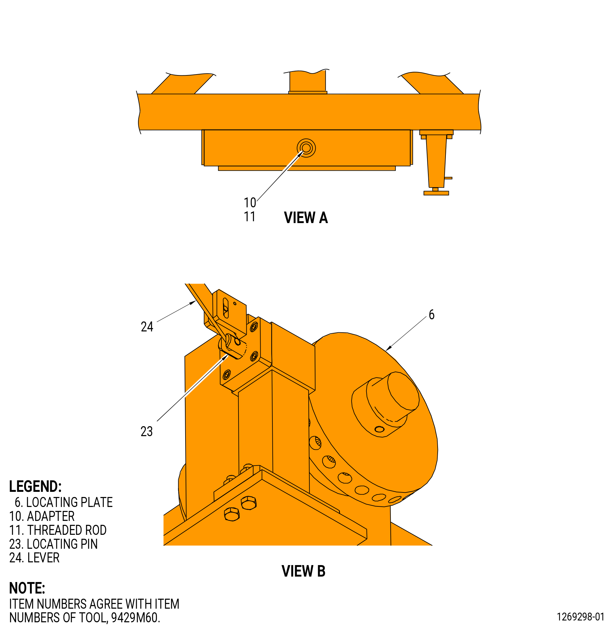
| 1 | If necessary, adjust the length of the stand with the adapter (item 10) and threaded rod (item 11). Record the stand length on the scale (item 32). |
| (c) | Attach the 11C4101 bracket to the adjustable adapter (item 15) and the fixed adapter (item 19) of the 9429M60 roll-over stand with 0.5 inch (12.7 mm) diameter by 1.25 inches (31.8 mm) long slave bolts and nuts at eight locations. Make sure that the slave bolts are the correct grade bolts for the application. |
| (d) | Move the lever (item 24) to disengage the locating pin (item 23) from the locating plate (item 6). |
| (e) | Rotate the hand wheel (item 31) to level the 11C4101 bracket. |
| CAUTION: |
|
| (f) | Move the lever (item 24) to prevent rotation of the locating plate (item 6). |
| Subtask 72-26-00-440-157 |
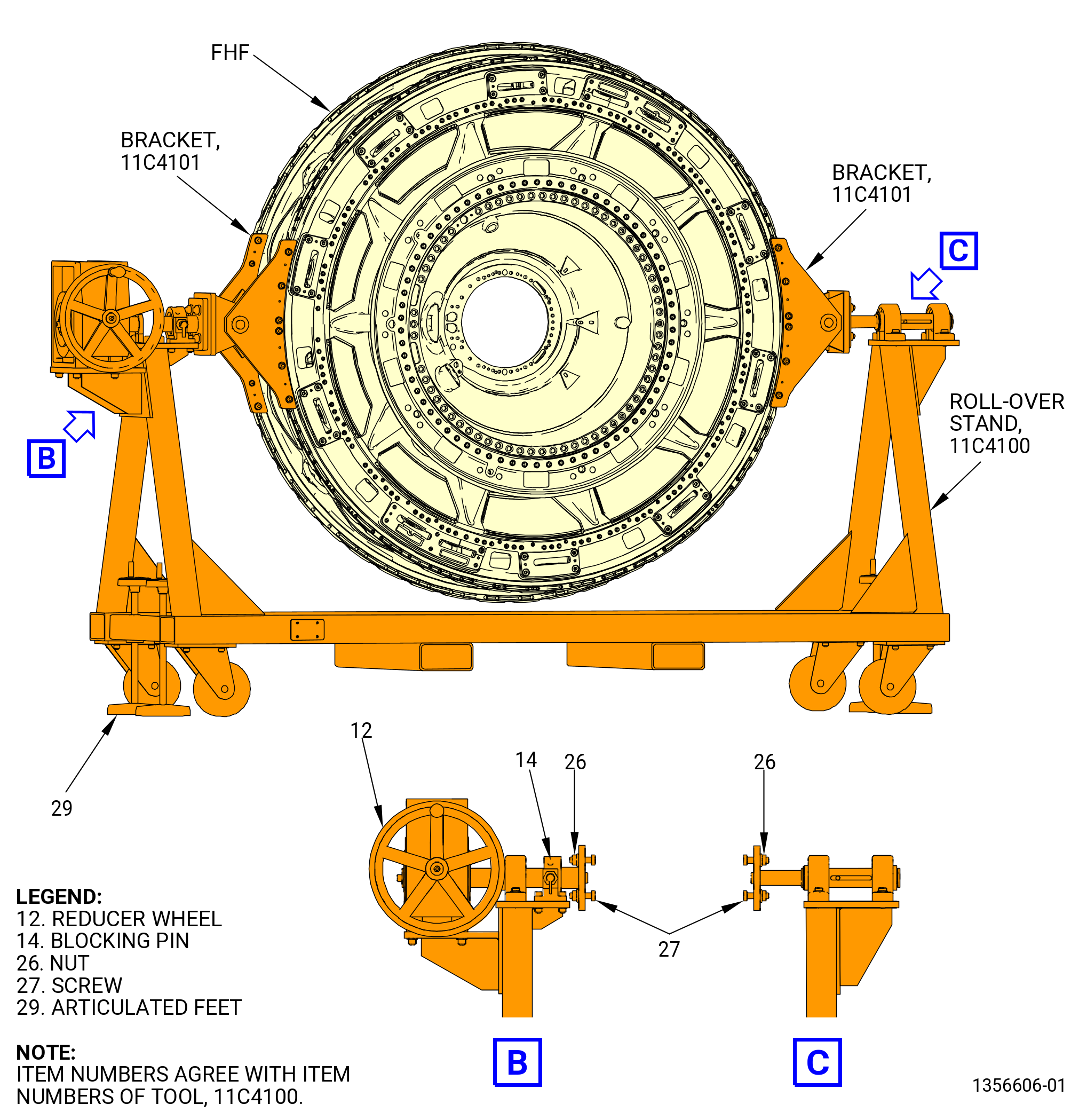
| (5).A. | Alternative Procedure. Install the FHF on the 11C4100 roll-over stand as follows. Refer to Figure 1004. |
| (a) | Turn the reducer wheel (item 12) to rotate the support shaft (reduction gearbox side) until a couple of holes is in horizontal direction. |
| (b) | Insert the blocking pin (item 14) in the relevant hole to lock the support shaft. |
| (c) | Unlock the screws that fix the support shaft on the opposite side along its axial direction and push it back in fully closed position to get the maximum gap. |
| (d) | Carefully lower the fan hub module on the 11C4100 roll-over stand until the 11C4101 bracket flange touches the stand flange. If necessary, carefully move the stand. |
| CAUTION: |
|
| (e) | Lower the four articulated feet (item 29) of the 11C4100 roll-over stand until they touch the floor. The four articulated feet must touch the floor to prevent movement of the assembly stand. Make sure that the roll-over stand is level. |
| (f) | Insert the four screws (item 27) through the stand and bracket flanges and lock them with the relevant nuts (item 26). |
| (g) | Remove the support shaft on the opposite side of the stand until its flange touches the bracket flange. |
| (h) | Lock the screws that fix the support shaft along its axial direction. |
| (i) | Carefully lower the overhead hoist and remove the 9429M19 vertical lift fixture. |
| Subtask 72-26-00-440-137 |
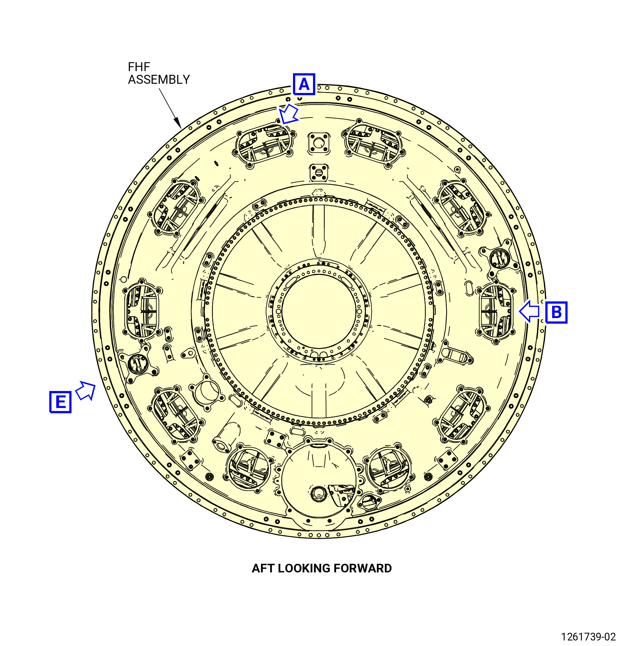
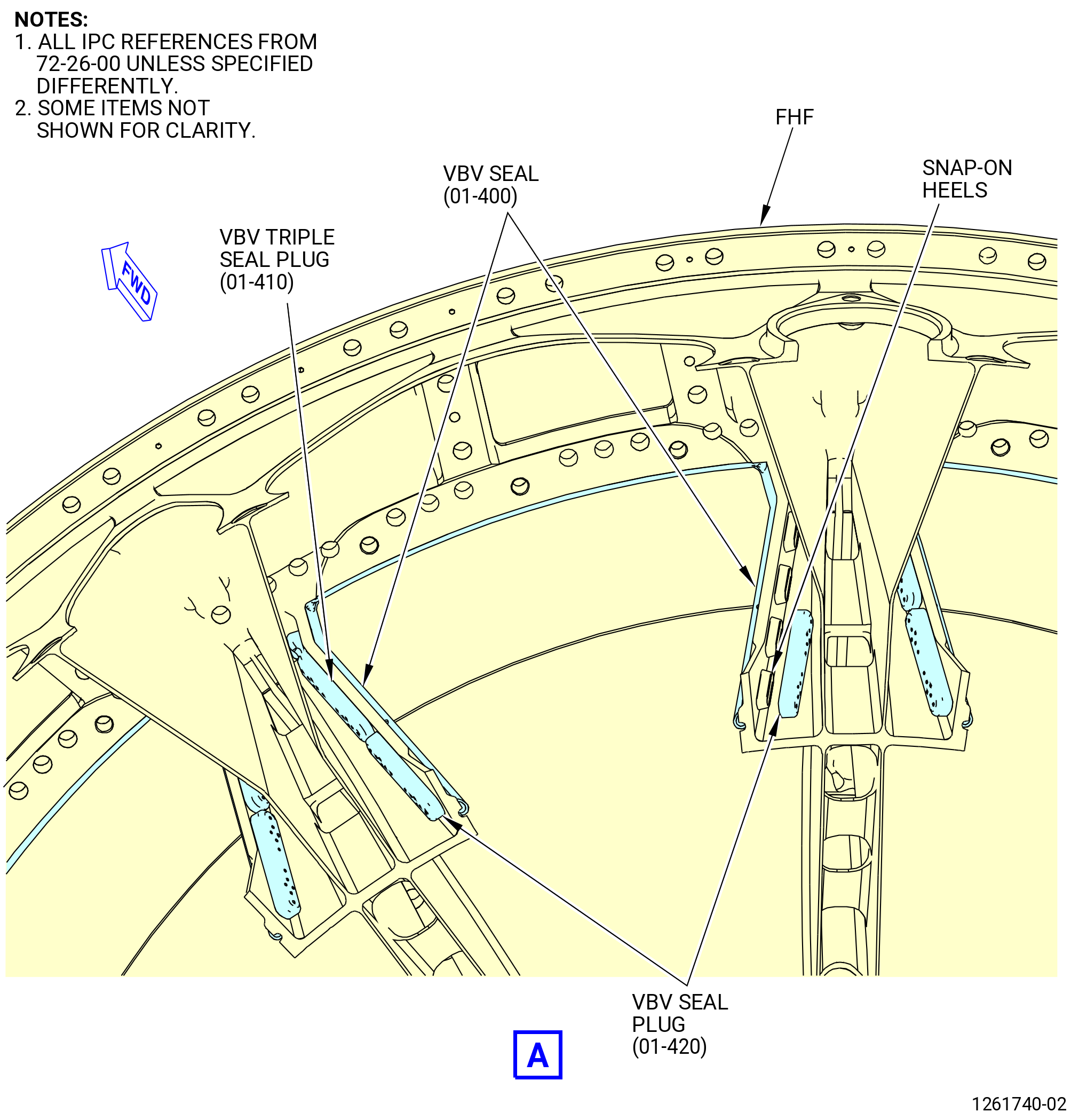
| B. | Install the variable bypass seals (VBV seal) (01-400) (SIN 840N0), variable bypass seal plugs (VBV seal plug) (01-420) (SIN 840N3), and variable bypass seal triple plugs (VBV triple seal plug) (01-410) (SIN 840N8) to the FHF. Refer to Figure 1006 and do as follows: |
| Subtask 72-26-00-140-001 |
| WARNING: |
|
| (1) | Lightly hand sand the VBV seals, VBV seal plugs, and VBV triple seal plugs with 300-400 sanding cloth to rough surface of the seals to help in the installation. |
| Subtask 72-26-00-110-001 |
| WARNING: |
|
| (2) | Use a C04-035 isopropyl alcohol and a clean C10-182 cleaning cloth to remove sanding particles. |
| Subtask 72-26-00-440-154 |
| (3) | Install the VBV seals in the FHF and push it into position. Make sure that the snap-on heels engage the FHF. |
| Subtask 72-26-00-360-001 |
| (4) | Bond two of the VBV triple seal plugs and two VBV seal plugs to the VBV seals with C01-178 RTV adhesive, press all four plugs in place and remove excess RTV. |
| Subtask 72-26-00-440-155 |
| (5) | Let the RTV cure for 24 hours. |
| Subtask 72-26-00-440-138 |
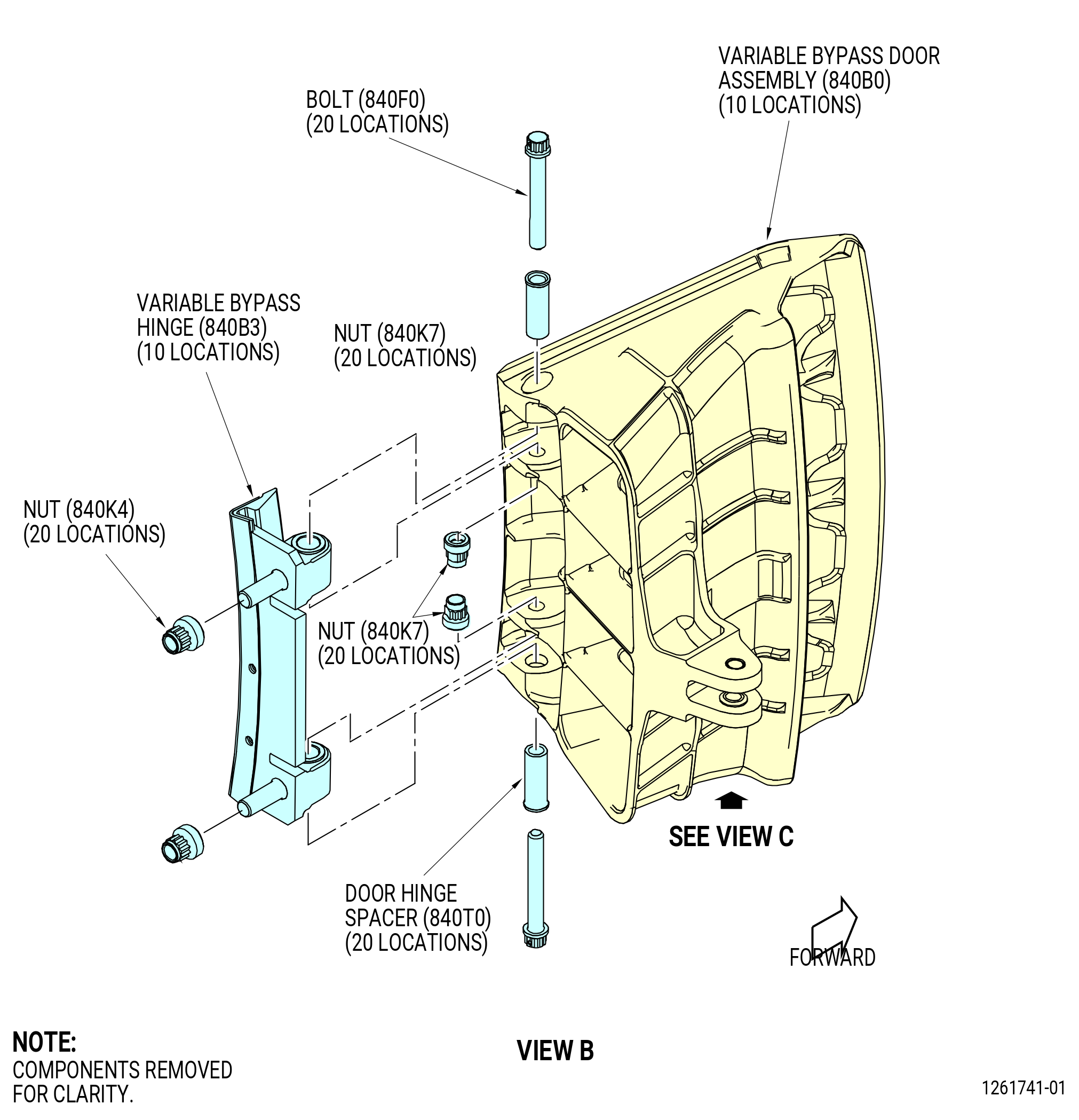
| C. | Install the variable bypass hinge (VBV hinge) (840B3) to the variable bypass door (VBV door) (840B0) as follows: |
| (1) | Apply C02-058 lubricant to the bolts (840F0), spacers (840T0), and nuts (840K7). |
| (2) | Install the VBV hinge on to the door with the bolts, spacers and nuts. |
| (3) | Torque the nuts to 120-130 lb. in (13.6-14.7 N.). |
| Subtask 72-26-00-220-037 |
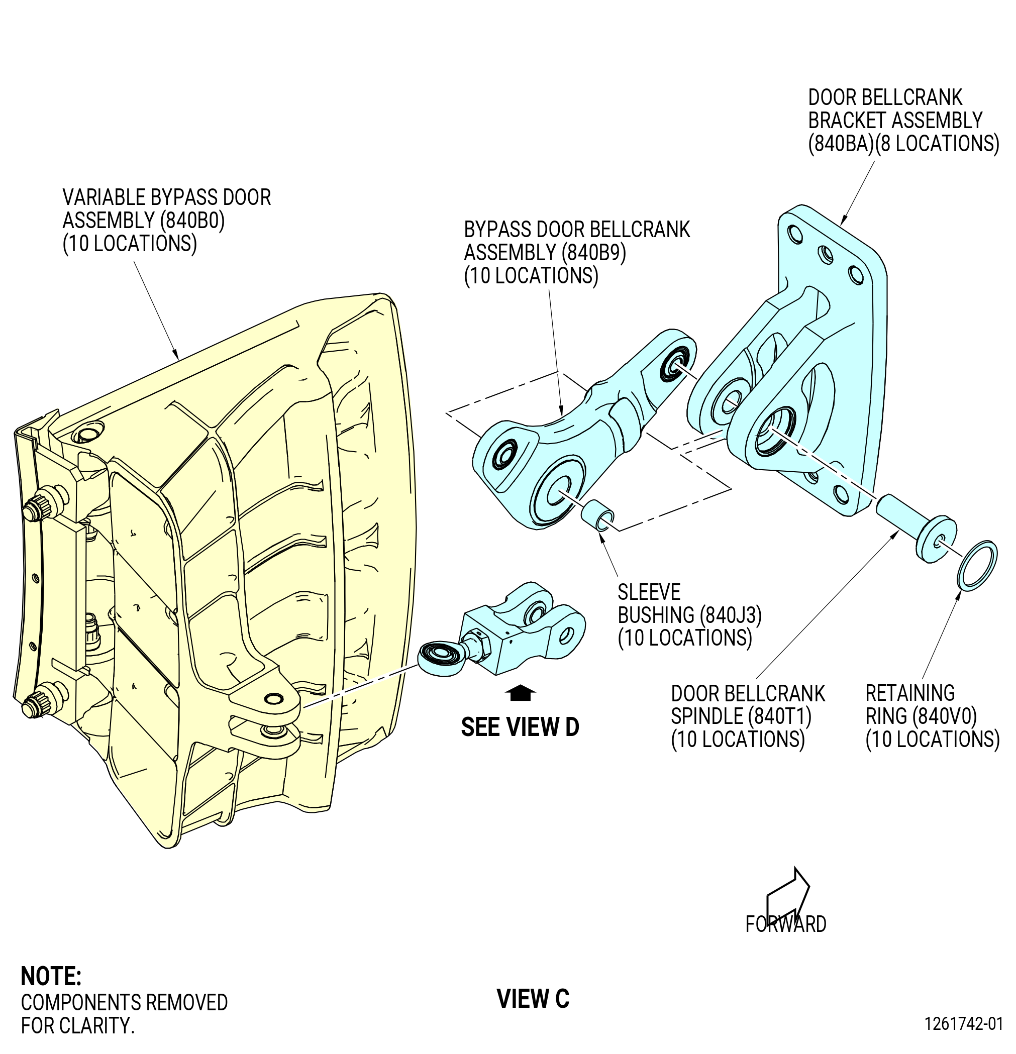
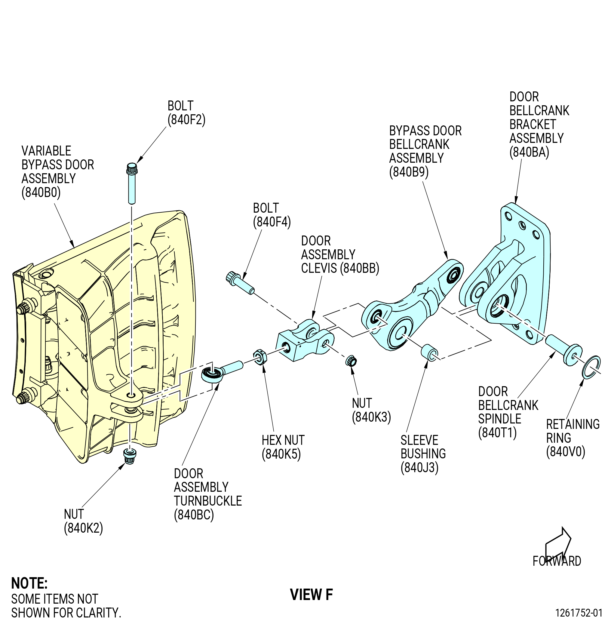
| D. | Install the bypass door bellcrank assembly (840B9) to the door bellcrank bracket assembly (840BA) as follows: |
| (1) | Install the sleeve bushing (840J3) in the bypass door bellcrank assembly. |
| (2) | Install the door bellcrank spindles (840T1) through the door bellcrank bracket assemblies and the bypass door bellcrank assemblies. |
| (3) | Install the retaining rings (840V0) in the groove, if necessary turn the retaining rings to install them in the grooves correctly. |
| Subtask 72-26-00-440-139 |
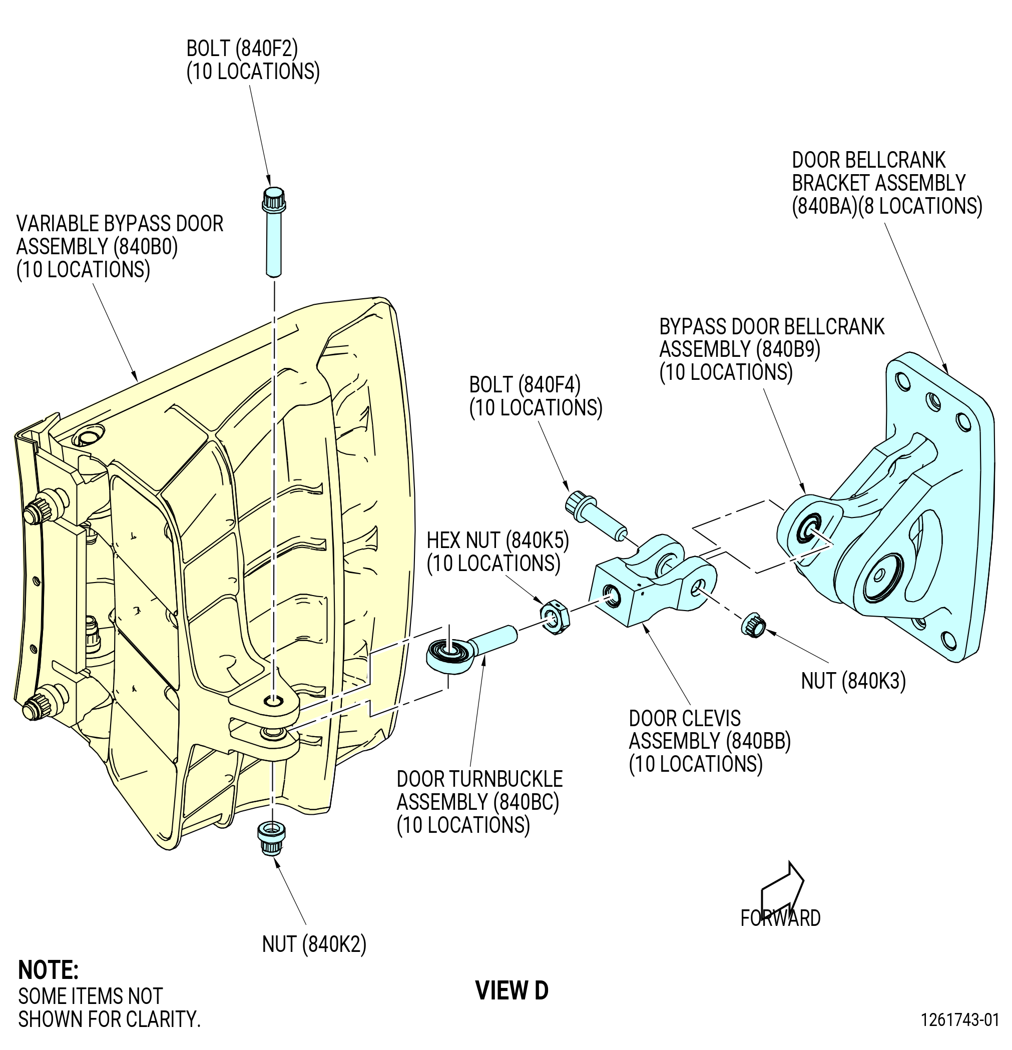
| E. | Install the door clevis assembly (840BB) and the door turnbuckle assembly (840BC) to the bypass door bellcrank assembly (840B9) as follows: |
| (1) | Install the door clevis assembly on the bypass door bellcrank assembly with the bolt (840F4) and nut (840K3) in eight locations. |
| (2) | Torque the nut (840K3) to 100-110 lb. in (11.3-12.4 N.m). |
| (3) | Thread the hex nut (840K5) on to the door turnbuckle assembly as far as possible in eight locations. |
| (4) | Install the door turnbuckle assembly with the hex nut (840K5) attached into the door clevis assembly. |
| (5) | Make sure that there is approximately 0.14 inch (3.6 mm) free thread on the outside of the clevis. |
| (6) | Tighten the hex nut (840K5) manually to safety the parts in the correct position. |
| Subtask 72-26-00-440-140 |
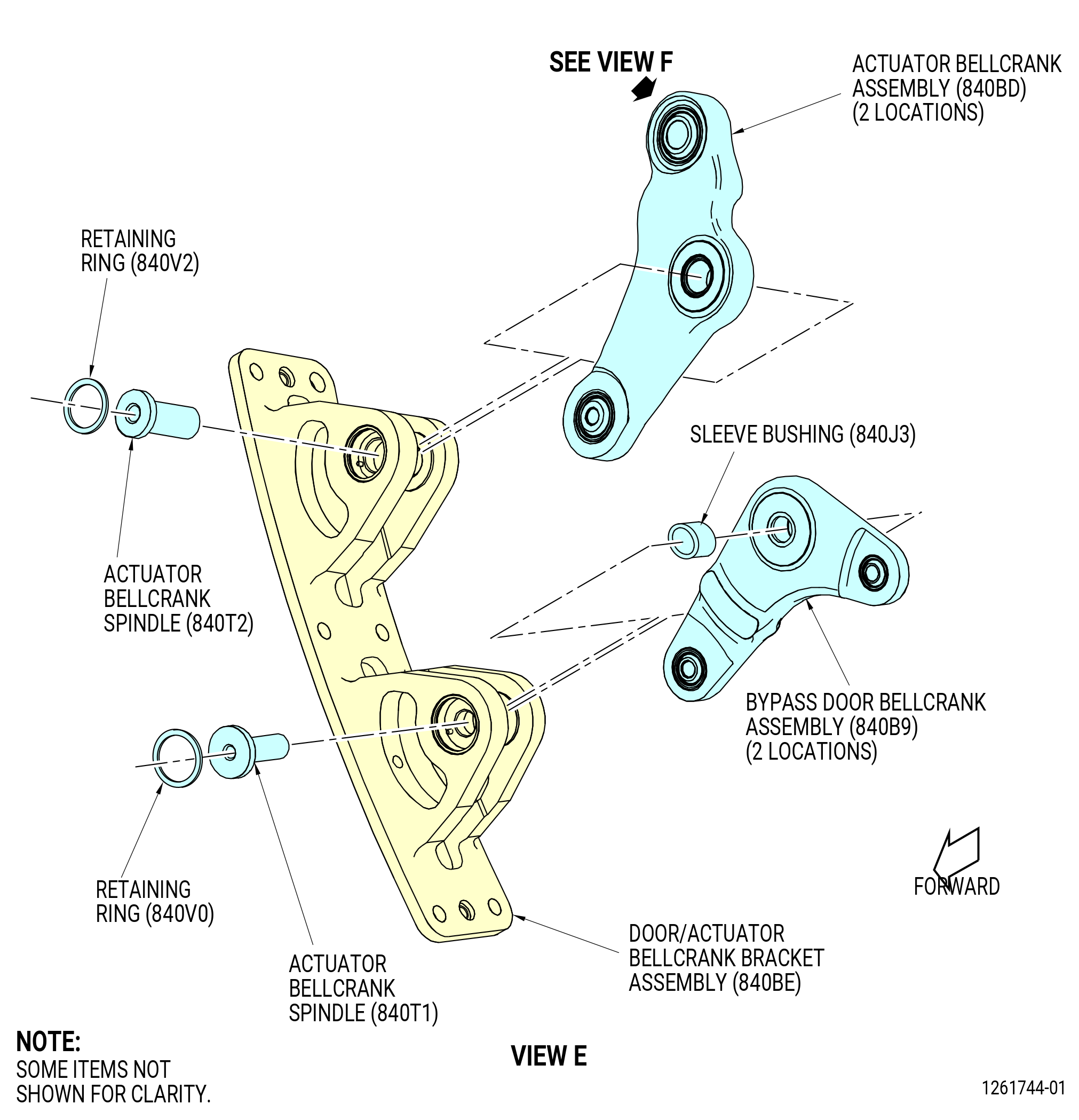
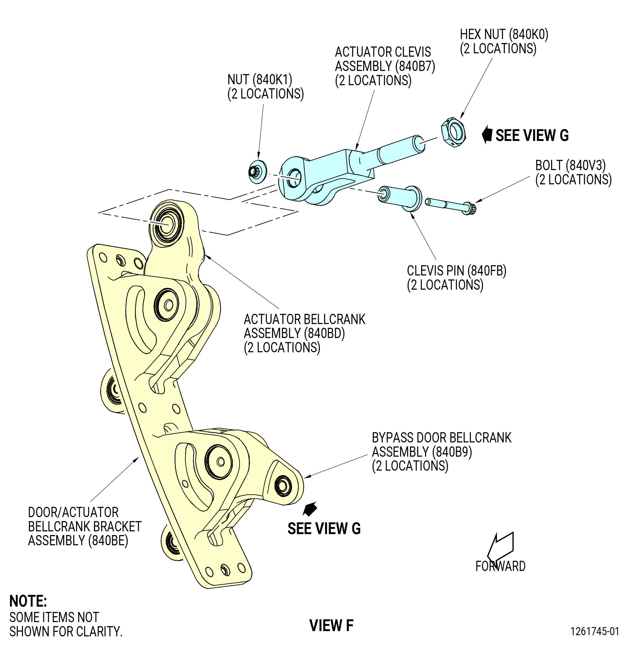
| F. | Install the bypass door bellcrank assembly (840B9) and the actuator bellcrank assembly (840BD) to the door/actuator bellcrank bracket assembly (840BE) as follows: |
| (1) | Put the sleeve bushing (840J3) in the bypass door bellcrank assembly in two locations. |
| (2) | Attach the bypass door bellcrank assembly (840B9) to the door/actuator bellcrank bracket assembly (840BE) with the door bellcrank spindle (840T1). |
| (3) | Install the retaining ring (840V0) in the groove, if necessary turn the retaining ring to install in the groove correctly. |
| (4) | Attach the actuator bellcrank assembly (840BD) to the door/actuator bellcrank bracket assembly (840BE) with the door bellcrank spindle (840T2). |
| (5) | Install the retaining ring (840V2) in the groove, if necessary turn the retaining ring to install in the groove correctly. |
| Subtask 72-26-00-440-141 |
| G. | Install the actuator clevis assembly (840B7) to the actuator bellcrank assembly (840BD) as follows: |
| (1) | Attach the actuator clevis assembly to the actuator bellcrank assembly (840BD) with the actuator clevis pin (clevis pin) (840FB). |
| (2) | Install the bolt (840V3) and nut (840K1) through clevis pin (840FB) of the actuator bellcrank assembly (840BD). |
| (3) | Install the hex nut (840K0) on the actuator clevis assembly (840B7) until the hex nut touches the clevis. |
| (4) | Install the actuator turnbuckle assembly (840W0) into the hex nut (840K0). |
| (5) | Torque the nut (840K1) to 110-120 lb. in (12.4-13.6 N.m). |
| Subtask 72-26-00-440-142 |
| H. | Install the door clevis assembly (840BB) and the door turnbuckle assembly (840BC) to the bypass door bellcrank assembly (840B9) as follows: |
| (1) | Install the door clevis assembly on the bypass door bellcrank assembly with the bolt (840F4) and nut (840K3). |
| (2) | Torque the nut (840K3) to 100-110 lb. in (11.3-12.4 N.m). |
| (3) | Thread the hex nut (840K5) on to the door turnbuckle assembly (840BC) as far as possible. |
| (4) | Install the door turnbuckle assembly (840BC) with the hex nut (840K5) attached in to the door clevis assembly |
| (5) | Make sure that there is approximately 0.14 inch (3.6 mm) free thread on the outside of the door clevis assembly (840BB). |
| (6) | Tighten the hex nut (840K5) manually to safety the parts in the correct position. |
| Subtask 72-26-00-440-143 |
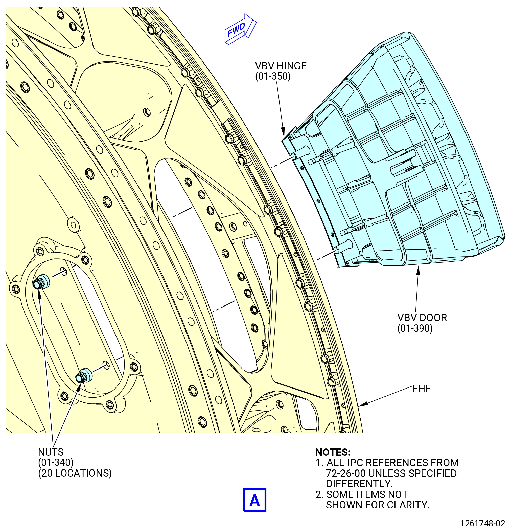
| I. | Install the VBV doors (01-390) (SIN 840B0) and the VBV hinges (01-350) (SIN 840B3) to the FHF. Refer to Figure 1007 and do as follows: |
| (1) | Apply C02-058 lubricant to the threads of the bolt studs on the VBV hinges and the nuts (840K4). |
| (2) | Install the VBV door assemblies into the FHF. |
| (3) | Align the studs of the VBV hinges with the FHF boltholes. |
| (4) | Attach the nuts (840K4) to the FHF and tighten. |
| Subtask 72-26-00-440-144 |
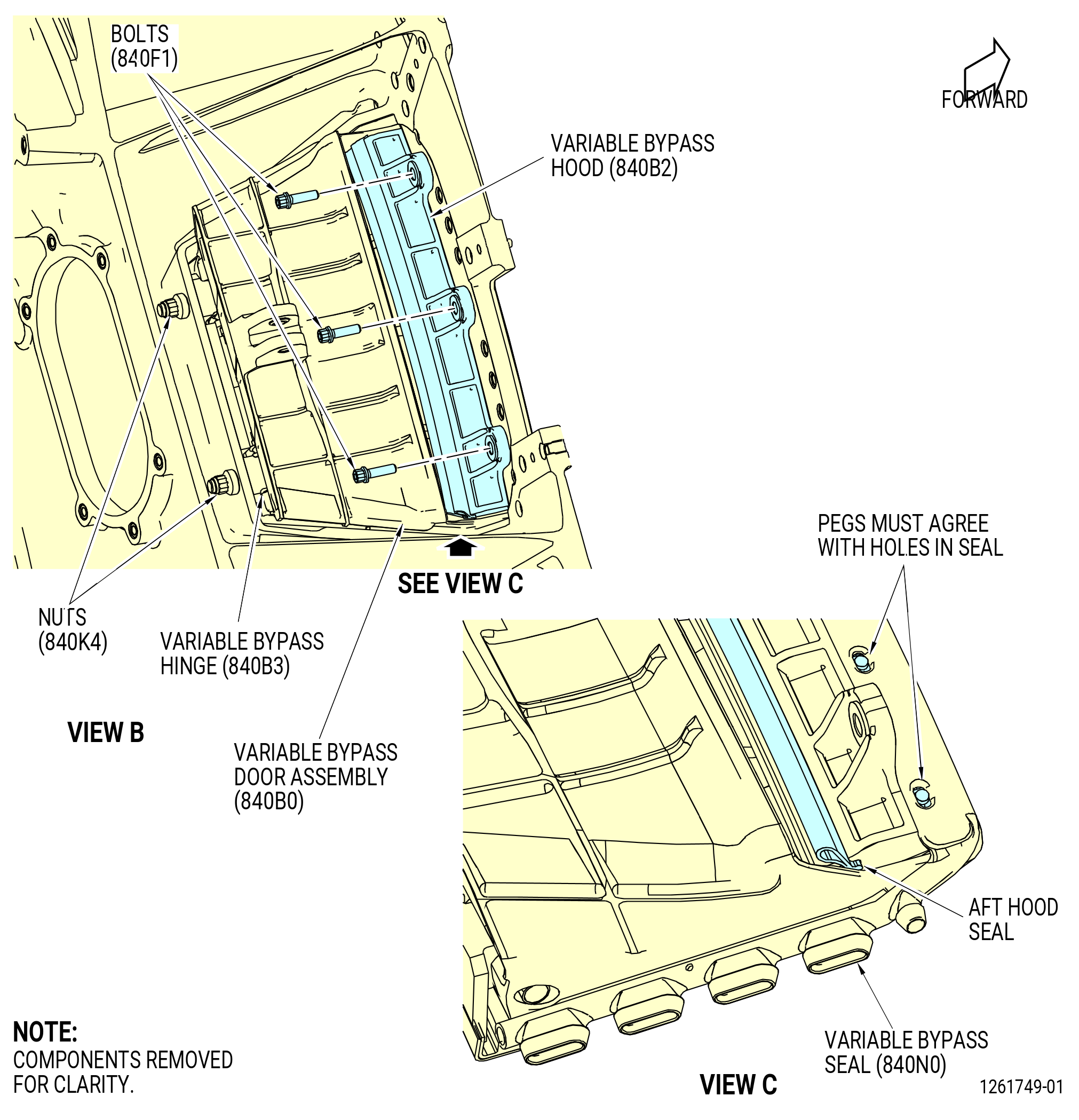
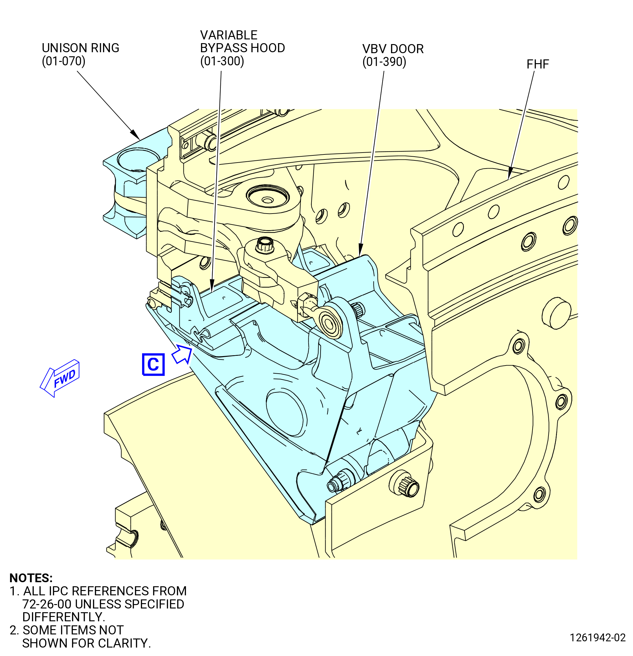
| J. | Install the VBV hoods (840B2) to the VBV doors (840B0) as follows. Refer to Figure 1007. |
| (1) | Install the each VBV hood in position on the each VBV door and make sure that the hood pushes the VBV seal (01-400) (SIN 840N0) against the FHF. |
| (2) | Apply C02-058 lubricant to the threads of the bolts (840F1) |
| (3) | Install the VBV hood with the bolt. |
| (4) | Tighten the bolts hand tight, then release the bolt one half of a turn. |
| (5) | Make sure that the hood moves and align the stud in the bypass hood (840B2) with the holes in the VBV seal (840N0). |
| Subtask 72-26-00-210-002 |
| K. | Examine the VBV doors (840B0) against the VBV seals (840N0) as follows. Refer to Figure 1006. |
| (1) | Install the 11C3700 adjustment tool and put the VBV door against the VBV seal with the forward lip of the VBV door along the VBV seal. |
| (2) | Adjust the radial position of the VBV doors and VBV hinges for the same clearance on all sides. |
| (3) | Tighten the nut (840K4) to attach the VBV door and VBV hinge to that position. |
| (4) | Use a vernier caliper to measure the distance between the FHF and the VBV door and make sure that the distance is equal from edge to edge. |
| (5) | Torque the nuts (840K4) to 210-230 lb. in (23.7-26.0 N.m). |
| (6) | Torque the bolts (840F1) to 110-120 lb. in (12.4-13.6 N.m). |
| (7) | Make sure that the forward edge of the VBV door is not farther out than the diameter between the VBV doors. |
| (8) | Make sure that the VBV seal is against the sides of the VBV doors and that the distance between the VBV door and the FHF is the same. |
| (9) | Make sure that the VBV door and VBV hinge are aligned with flow duct radially. |
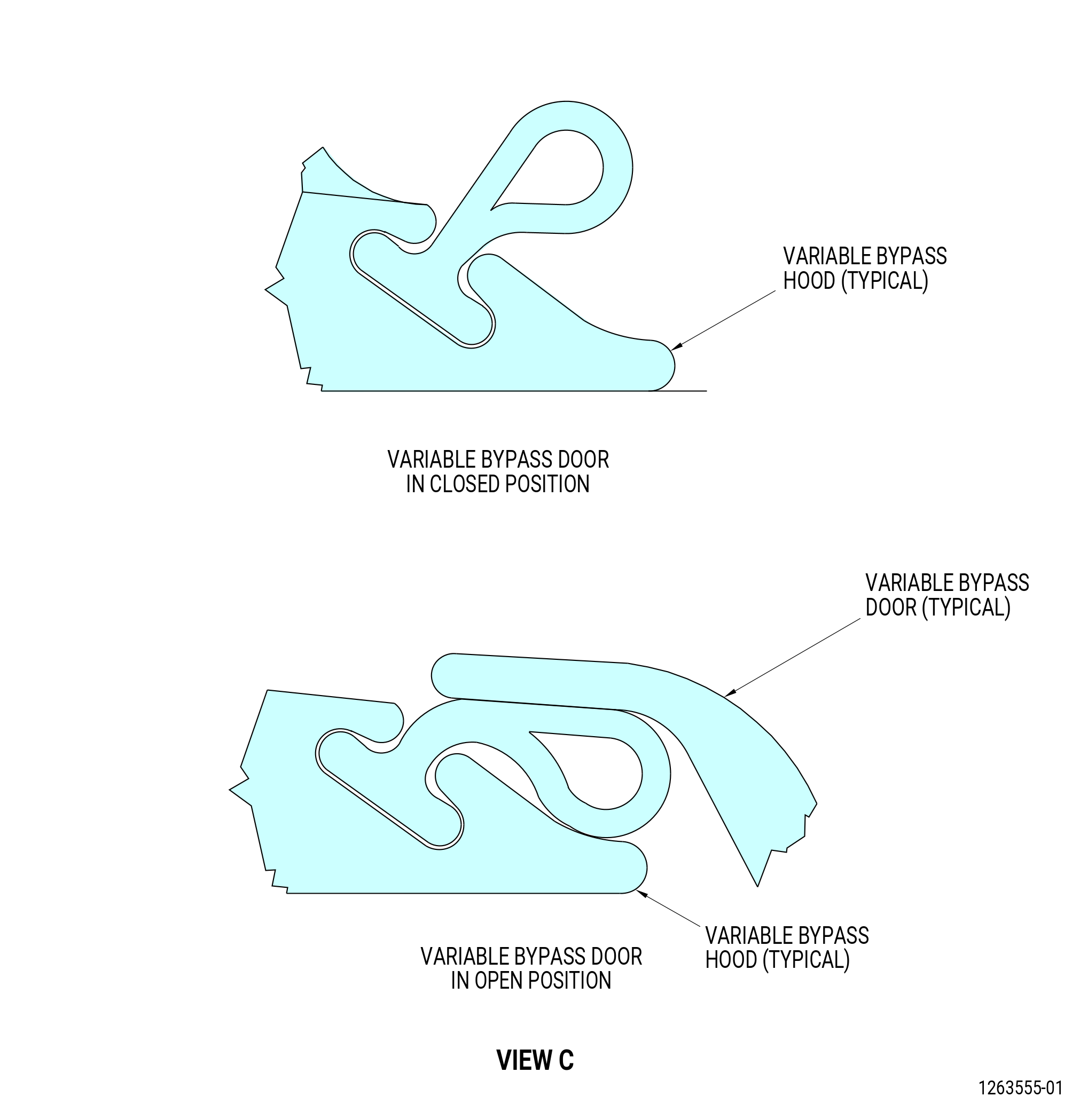
| (10) | Make sure that the VBV seal on the VBV hood is sealed on the VBV door. |
| (11) | Make sure that the VBV door edge does not touch the plastic on the VBV hood when the VBV hood is fully open and the VBV hood seal must not fold back. Refer to Figure 1008. |
| Subtask 72-26-00-440-145 |
| L. | Install the bellcrank assemblies in the FHF as follows: |
| NOTE: |
|
| (1) | Install the bellcrank assemblies through the bellcrank hole in the FHF. Refer to Figure 1007. |
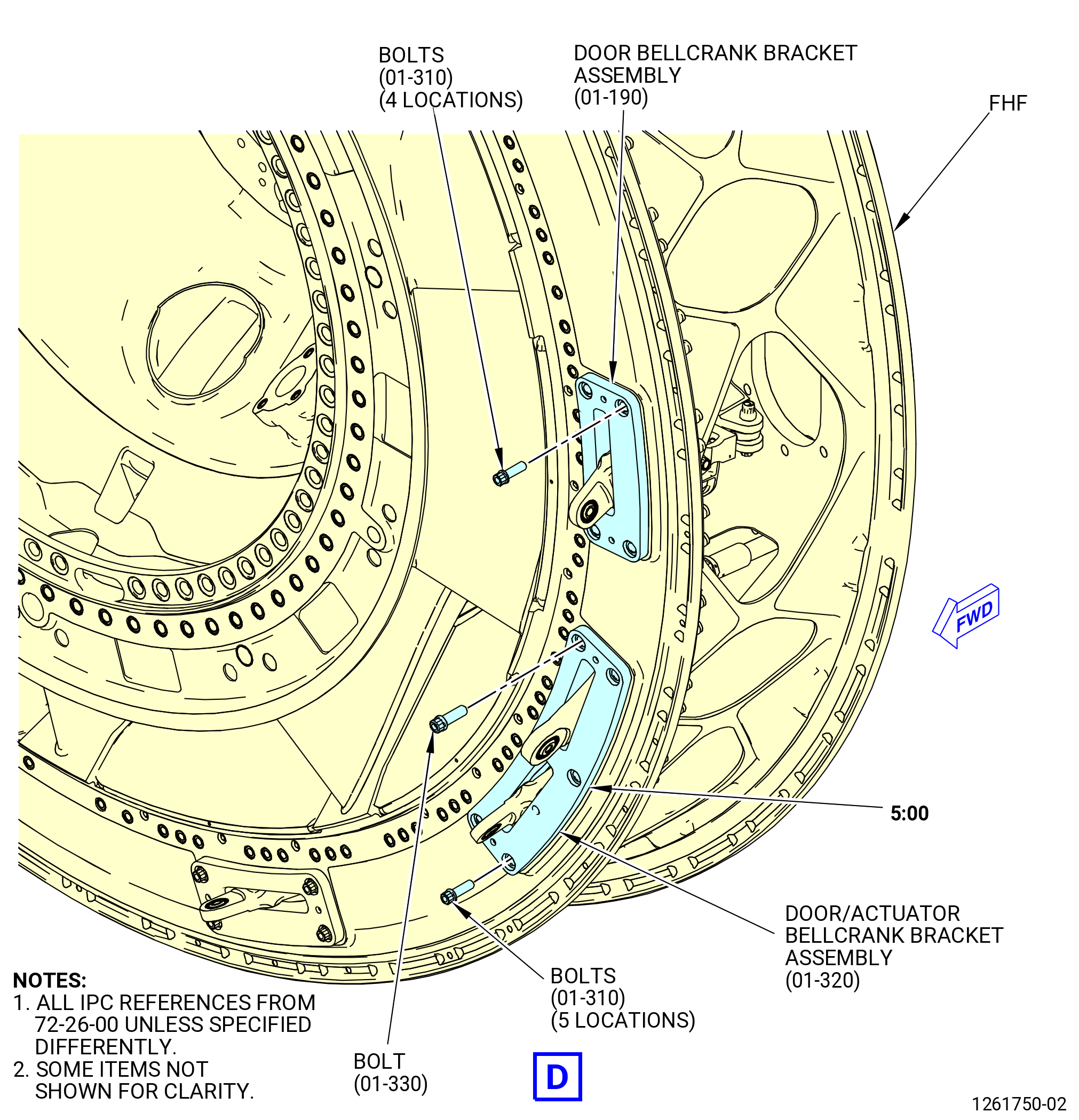
| (2) | Attach the door bellcrank bracket assemblies (840BA) with the bolts (840F5) in eight locations on the FHF. |
| (3) | Attach the door bellcrank bracket assemblies (840BE) with the five bolts (840F5) and one bolt (840F6) in two locations on the FHF. |
| (4) | Torque the bolts (840F5) to 205-225 lb. in (23.2-25.4 N.m). |
| (5) | Torque the bolts (840F6) to 380-420 lb. in (42.9-47.5 N.m). |
| Subtask 72-26-00-440-146 |
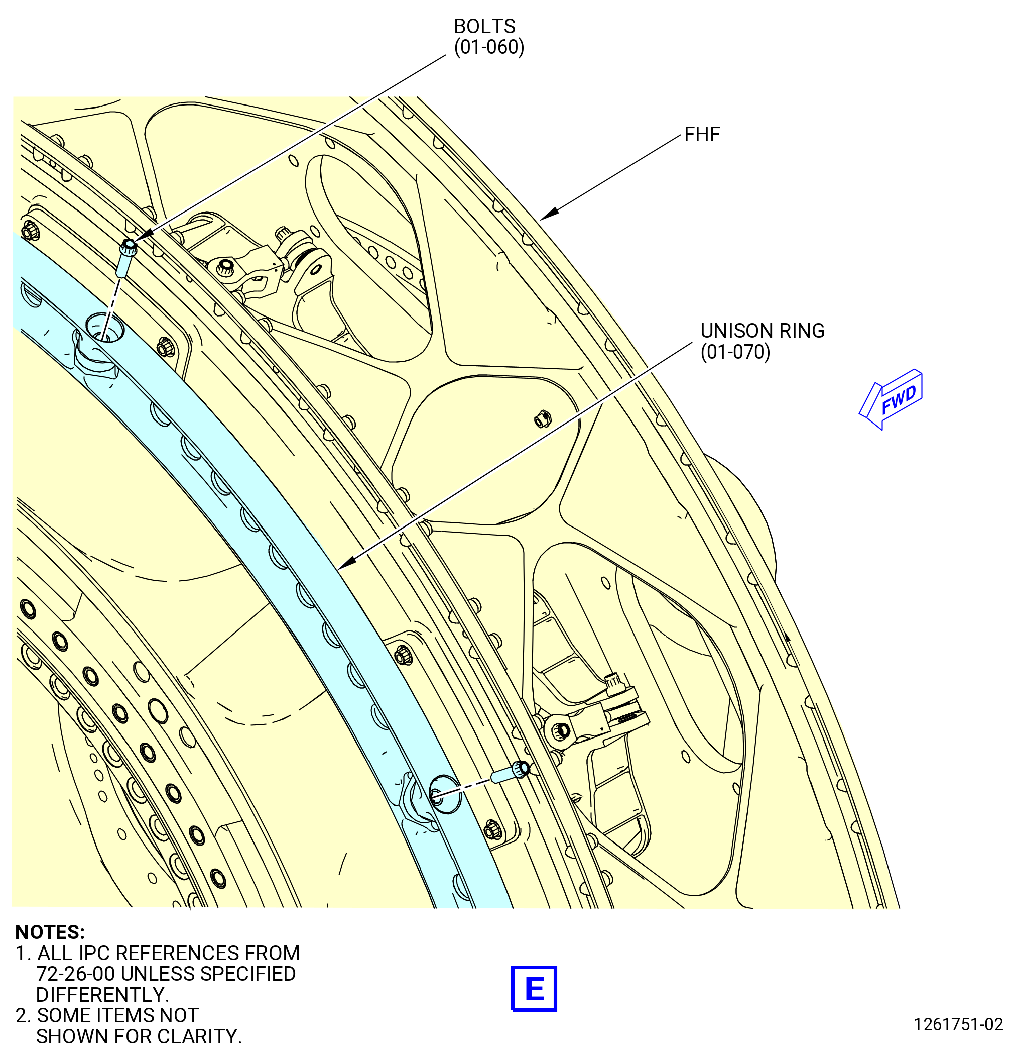
| M. | Install the unison ring (01-070) (SIN 840B6) on to the FHF. Refer to Figure 1007 and do as follows: |
| NOTE: |
|
| (1) | Use the 9429M60 roll-over stand or 11C4100 roll-over stand to turn the FHF to the horizontal position, aft side up. |
| (2) | Put all the VBV bellcrank assemblies (840B9, 840BD) to the end position. |
| (3) | Install the unison ring assembly with the X mark at the 12:00 o'clock position on the FHF. |
| (4) | Put the bolts (840F3) through the unison ring assembly and the VBV bellcrank assemblies (840B9) at 10 locations hand tighten the bolt. |
| Subtask 72-26-00-220-038 |
| N. | Examine the VBV door system and make adjustments as follows. Refer to Figure 1006 and Figure 1009. |
| (1) | Use the 11C3702 location pin to put the unison ring (840B6) in the correct position. |
| (2) | Put the 11C3700 adjustment tools into the flow duct of the VBV door (840B0) (one tool for each door). |
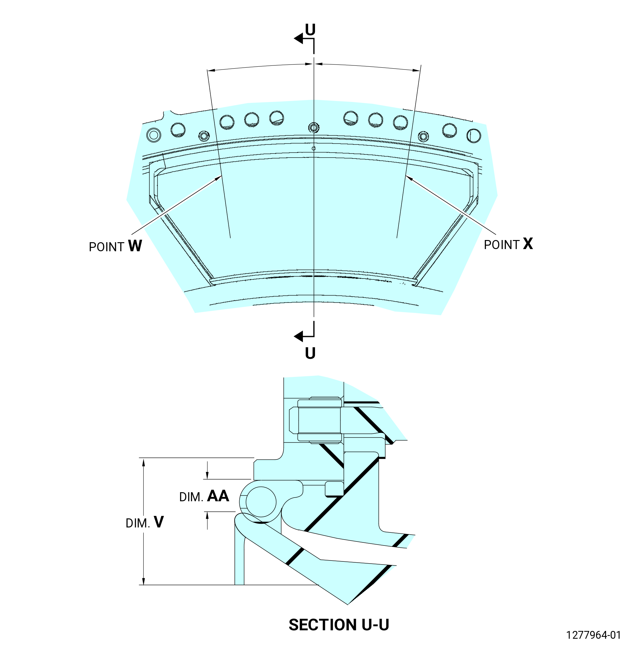
| (3) | Measure dimension AA at each door. |
| (4) | Adjust the ten 11C3700 adjustment tools until dimension AA is 0.243-0.343 inch (6.17-8.71 mm) for each door. |
| (5) | Install the 11C3703 rigging tool on the master part and set the dials to zero. |
| (6) | Install the 11C3703 rigging tool on the FHF and make sure that dimension V is not more than 1.14177 inches (29.0010 mm) at points W and X. If both dimension AA and V does not meet simultaneously, dimension AA must be 0.243-0.343 inch (6.17-8.71 mm) on all the doors and dimension V is acceptable up to a maximum of 1.152 inches (29.26 mm) at no more than five doors. Refer to Figure 1009. |
| (7) | Tighten each expander of the 11C3703 rigging tool one half turn more. |
| (8) | Turn the door turnbuckle assembly (840BC) until you can move the bolt (840F2) through the VBV door (840B0) and the door turnbuckle assembly (840BC) with minimum tension in the linkage. |
| (9) | Install the nut (840K2) on the bolt (840F2) hand tight. |
| (10) | Install the actuator boss (part 1) of the 11C3701 actuator stroke tool with the bolts (30722) and nuts (30741) on the two actuator bosses. |
| (11) | Torque the bolt until the nut is in position, but not more than 225 lb. in (28.8 N.m). |
| (12) | Put the jaws (part 2) of the 11C3701 actuator stroke tool on the actuator turnbuckle assembly (840W0). |
| (13) | Turn the adjustment handle (part 3) of the 11C3701 actuator stroke tool to safety the actuator turnbuckle assembly (840W0). |
| (14) | Put the jaws (part 2) of the 11C3701 actuator stroke tool with the actuator turnbuckle assembly (840W0) through the actuator boss (part 1). |
| (15) | Make sure that the actuator turnbuckle assembly (840W0) aligns with the actuator clevis assembly (840B7). |
| (16) | Turn the jaws (part 2) of the 11C3701 actuator stroke tool to engage the threads of the actuator turnbuckle assembly (840W0) and the actuator clevis assembly (840B7). |
| (17) | Continue to turn the jaws (part 2) of the 11C3701 actuator stroke tool until the holes in the jaws (part 2) are at the holes of the actuator boss (part 1) are in the closed position. |
| (18) | Install one pin (part 5) through the jaws (part 2) and the groove on the actuator boss (part 1) to prevent movement of the part. |
| (19) | Remove two each of the 11C3702 location pins and ten each of the 11C3700 adjustment tools. |
| Subtask 72-26-00-440-147 |
| O. | Install and inspect the VBV door system as follows. Refer to Figure 1006 and Figure 1007. |
| (1) | Move all the VBV doors three times from fully closed position to fully open position. |
| (2) | Install the 11C3703 rigging tool on the master and set the dial to zero. |
| (3) | Install the 11C3703 rigging tool on the FHF and measure dimension V on all 10 doors to make sure that the value is correct. |
| (4) | Use a vernier caliper to measure dimension AA. Dimension AA must be 0.243-0.343 inch (6.17-8.71 mm) on all the doors. Refer to Figure 1009. |
| (5) | Make sure that the 11C3702 location pins can move through the unison ring (840B6) and into the door/actuator bracket (840BE). |
| (6) | Torque the nuts (840K2, 840K5) to 110-120 lb. in (12.4-13.6 N.m). |
| NOTE: |
|
| (7) | Torque the nut (840K0) to 510-570 lb. in (57.6-64.4 N.m) at two locations. |
| NOTE: |
|
| (8) | Make sure that the clevis and turnbuckle have clearance to move to the maximum open and maximum close position on the door and actuators. |
| (9) | Make sure that the you put a 0.00511 inch (0.13 mm) wire or pin through the indication hole in the actuator turnbuckle (840W0). |
| (10) | Make sure that there is a minimum of 0.118 inch (3.0 mm) remaining thread length outside of the nut (840K0). |
| (11) | Make sure that there is a minimum of 0.0098 inch (0.25 mm) remaining thread length on the back side of the VBV clevis (840BB). |
| (12) | Safety the nut (840K0) and the nut (840K5) with a safety wire C10-071 safety wire or C10-143 safety cable assembly. Refer to TASK 70-11-00-400-001 (FASTENER RETENTION PROCEDURES). |
| Subtask 72-26-00-440-148 |
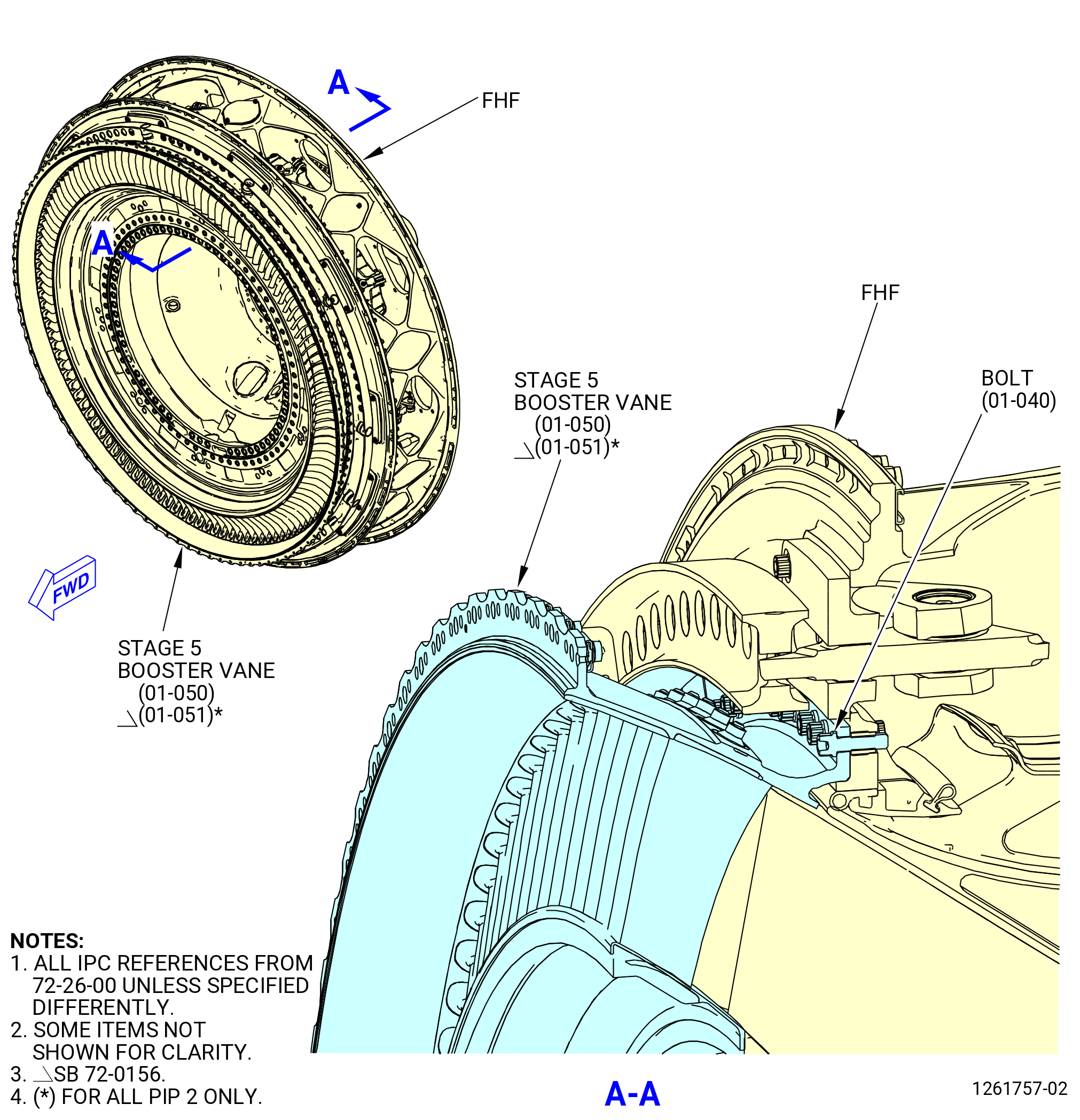
| P. | Install the FHS assembly vane 5 (stage 5 booster vanes) (01-050) (SIN 837AA) or (01-051) (SIN 837AA) on the FHF. Refer to Figure 1010 and do as follows: |
| NOTE: |
|
| WARNING: |
|
| (1) | Apply C02-058 lubricant to the machine bolts (bolts) (01-040) (SIN 837F4) before the stage 5 booster vanes are installed. |
| (2) | Install the three 11C3448 threaded guide pins to align the stage 5 booster vanes with the boltholes. |
| (3) | Remove the unison ring (840B6) and attach it to the forward flange of the stage 5 booster vanes at eight locations with plastic tie wraps. |
| (4) | Put the X mark on the unison ring at the 12:00 o'clock position of the recess of the stage 5 booster vanes. |
| (5) | Attach the stage 5 booster vanes to the 10035331 lifting tool or 11C3836 vane assembly lift/turn fixture and put it in a vertical position above the FHF. |
| WARNING: |
|
| CAUTION: |
|
| (6) | Heat the stage 5 booster vanes rear flange as follows: |
| (a) | Use two hot-air guns mounted on stands. |
| (b) | Set hot-air guns to 752°F (400°C). |
| (c) | Heat from a distance of 1.57-2.36 inches (40-60 mm) |
| (d) | Heat 5-6 minutes turn the stage 5 booster slowly to heat the stage 5 booster vanes evenly. |
| (7) | Align the notch in the stage 5 booster vanes at 12:00 O'clock position. |
| (8) | Attach the stage 5 booster vanes to the FHF with five bolts (837F4) (one set) at four different locations 90 degrees apart, along the flange. |
| CAUTION: |
|
| (9) | Tighten the 20 bolts (837F4) in a criss-cross pattern to pull the stage 5 booster vanes against the flange of the FHF. If necessary use the 11C3447 torque adapter. |
| (10) | Remove the 11C3448 guide pins and install the remaining bolts (837F4) into the flange. |
| (11) | Torque the bolts (837F4) in a crisscross pattern to 235-275 lb. in (26.6-31.1 N.m). If necessary use the 11C3447 torque adapter. |
| (12) | Use a 0.0020 inch (0.05 mm) feeler gage to make sure that the stage 5 booster vanes flange is tight against the FHF flange. |
| (13) | Put the unison ring (840B6) over the 10 VBV bellcranks (840B9) and the two actuator bellcranks (840BD) and install with the 12 bolts (840F3) through the unison ring and the bellcranks hand tight. Refer to Figure 1007. |
| NOTE: |
|
| (14) | Torque the bolts (840F3) to 110-120 lb. in (12.4-13.6 N.m) in a crisscross pattern. |
| (15) | Use the crisscross pattern of 1, 6, 3, 8, 5, 10, 7, 2, 9, 4, and then the bolt in the actuator positions. |
| (16) | Move the VBV door system from the fully closed position to the fully open position a minimum of three times. |
| (17) | Make sure that the seal on the hoods is correctly sealed against the doors. |
| NOTE: |
|
| Subtask 72-26-00-220-039 |
| Q. | DELETED. |
| Subtask 72-26-00-440-149 |
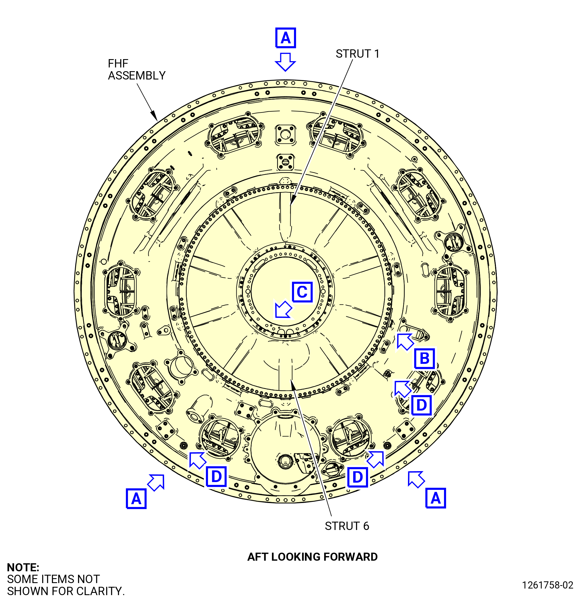
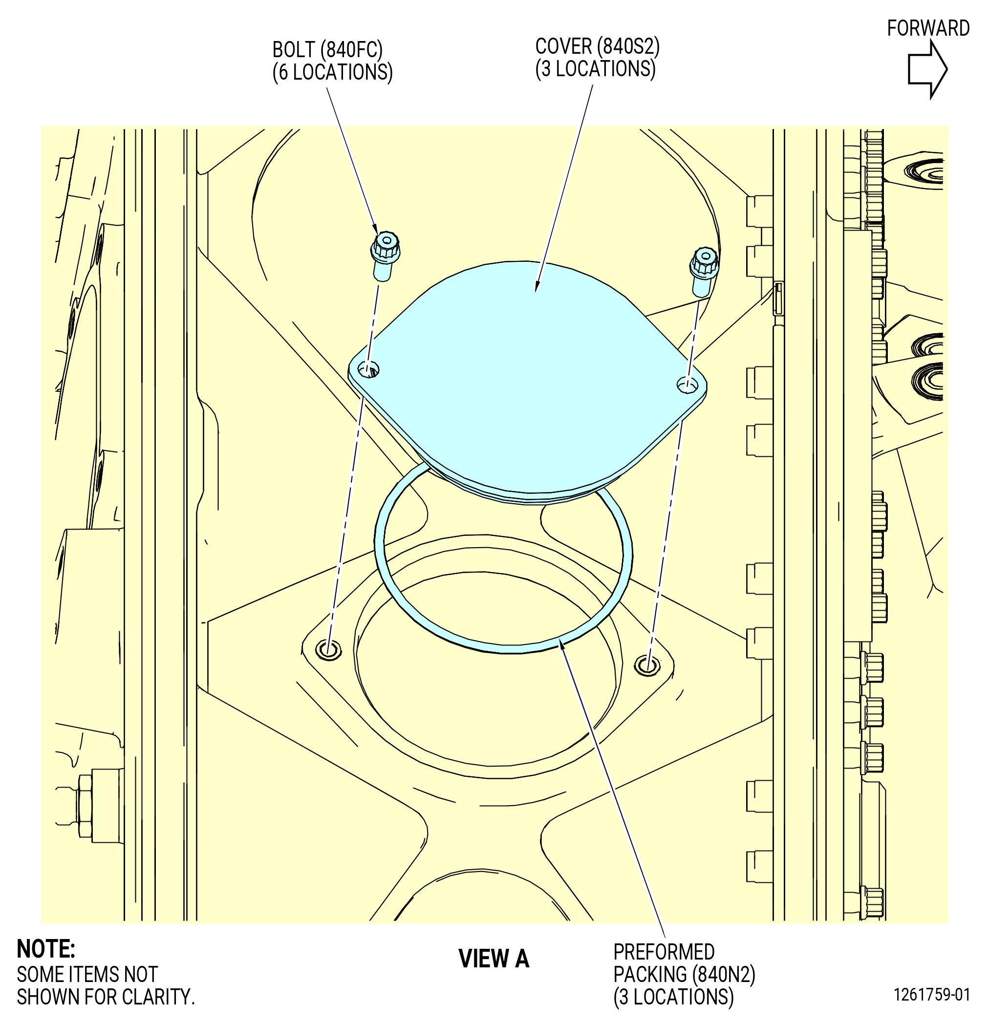
| R. | Install the strut covers (covers) (840S2) to the FHF as follows. Refer to Figure 1011. |
| (1) | Install the preformed packing (01-030) (SIN 840N2) on each of the three covers. |
| (2) | Install the covers at No. 1, 5, and 7 strut locations with the two bolts (840FC) for each cover. |
| (3) | Torque all the six bolts to 110-120 lb. in (12.4-13.6 N.m). |
| Subtask 72-26-00-220-040 |
| S. | Do a visual inspection of the borescope plugs and ports. Refer to TASK 72-00-00-800-804 (72-00-00, SPECIAL PROCEDURE 004) (paragraph 5.A. and 5.B.). |
| Subtask 72-26-00-440-150 |
| * * * PRE SB 72-0271 |
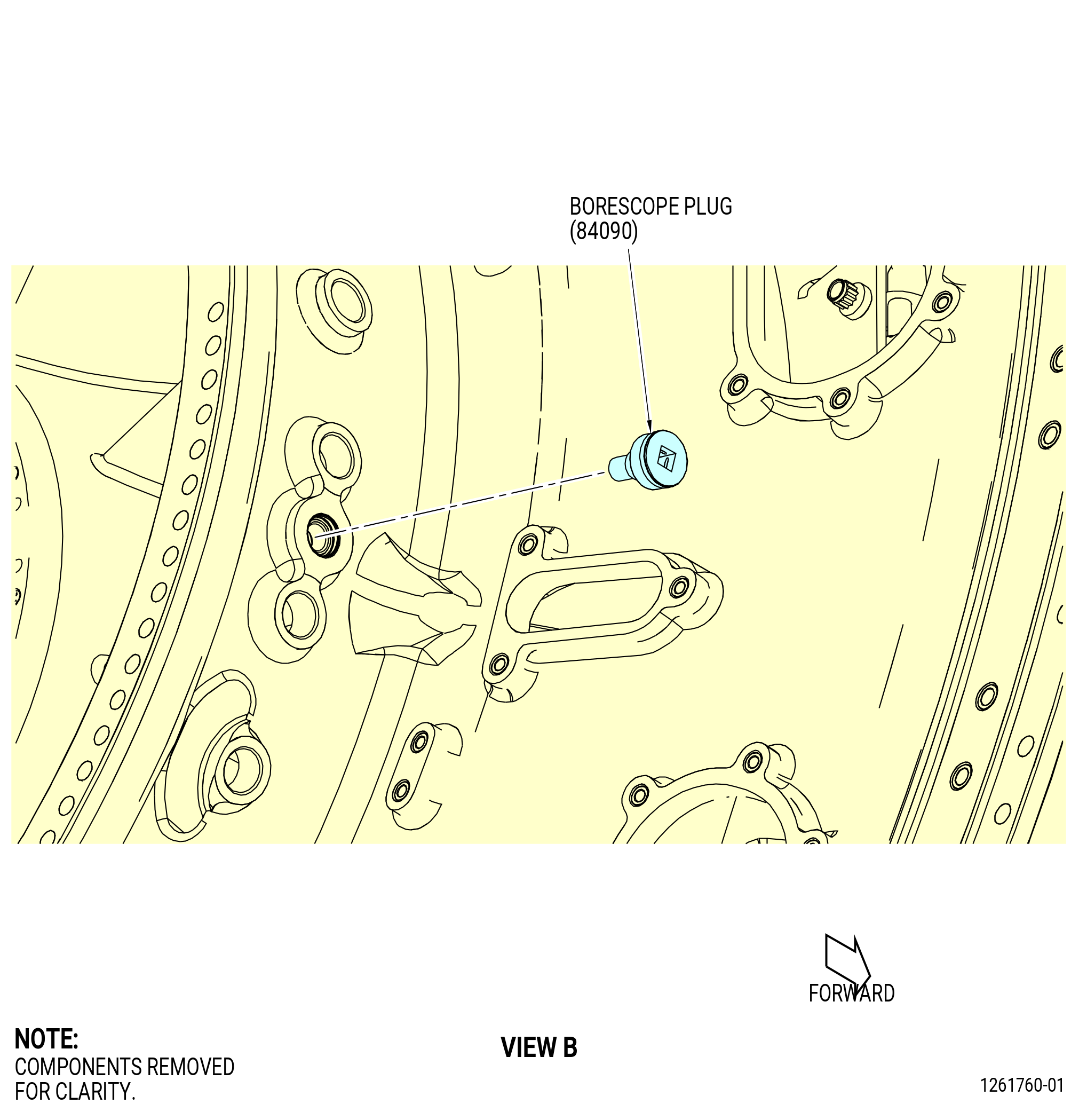
| T. | Install the borescope plug (01-450) (SIN 84090) into the FHF. Refer to Figure 1011 and do as follows: |
| (1) | Install the borescope plug at the 4:00 O'clock position into the FHF. |
| (2) | Torque the borescope plug to 110-140 lb. in (12.4-15.8 N.m). |
| (3) | After the plug has been torqued, perform a visual inspection of the plug and make sure that the locking feature is fully engaged with the lug on the borescope boss. Also make sure that the head of the borescope plug is fully seated against the borescope boss. If one of the two conditions are not met, the ratcheting feature of the plug can be seized or locked. Apply a penetrating oil directly in between the locking ring and the head of the plug. Re-apply torque to the plug until the plug begins to rotate freely. Tighten the plug from 110 to 140 lb in. (12.4 to 15.8 Nm). Do the visual inspection again before proceeding. If the conditions above cannot be met, replace the plug. Refer to Figure 1012. |
| * * * END PRE SB 72-0271 |
| Subtask 72-26-00-440-164 |
| * * * SB 72-0271 |
| T.A. | Install the borescope plug (01-450) (SIN 84090) into the FHF. Refer to Figure 1011 and do as follows: |
| NOTE: |
|
| (1) | Install the borescope plug at the 4:00 o'clock position into the FHF. |
| (2) | Torque the borescope plug to 110 to 140 lb. in (12.4 to 15.8 Nm). |
| (3) | After you torque the plug, do a visual inspection of the plug and make sure that the head of the borescope plug is fully seated against the borescope boss. If this condition is not met, the ratcheting feature of the plug can be seized or locked. Apply a penetrating oil directly in between the locking ring and the head of the plug. Re-apply torque to the plug until the plug begins to rotate freely. Tighten the plug from 110 to 140 lb in. (12.4 to 15.8 Nm). Do the visual inspection again before you continue. If the condition above cannot be met, replace the plug. Refer to Figure 1012. |
| * * * END SB 72-0271 |
| Subtask 72-26-00-440-151 |
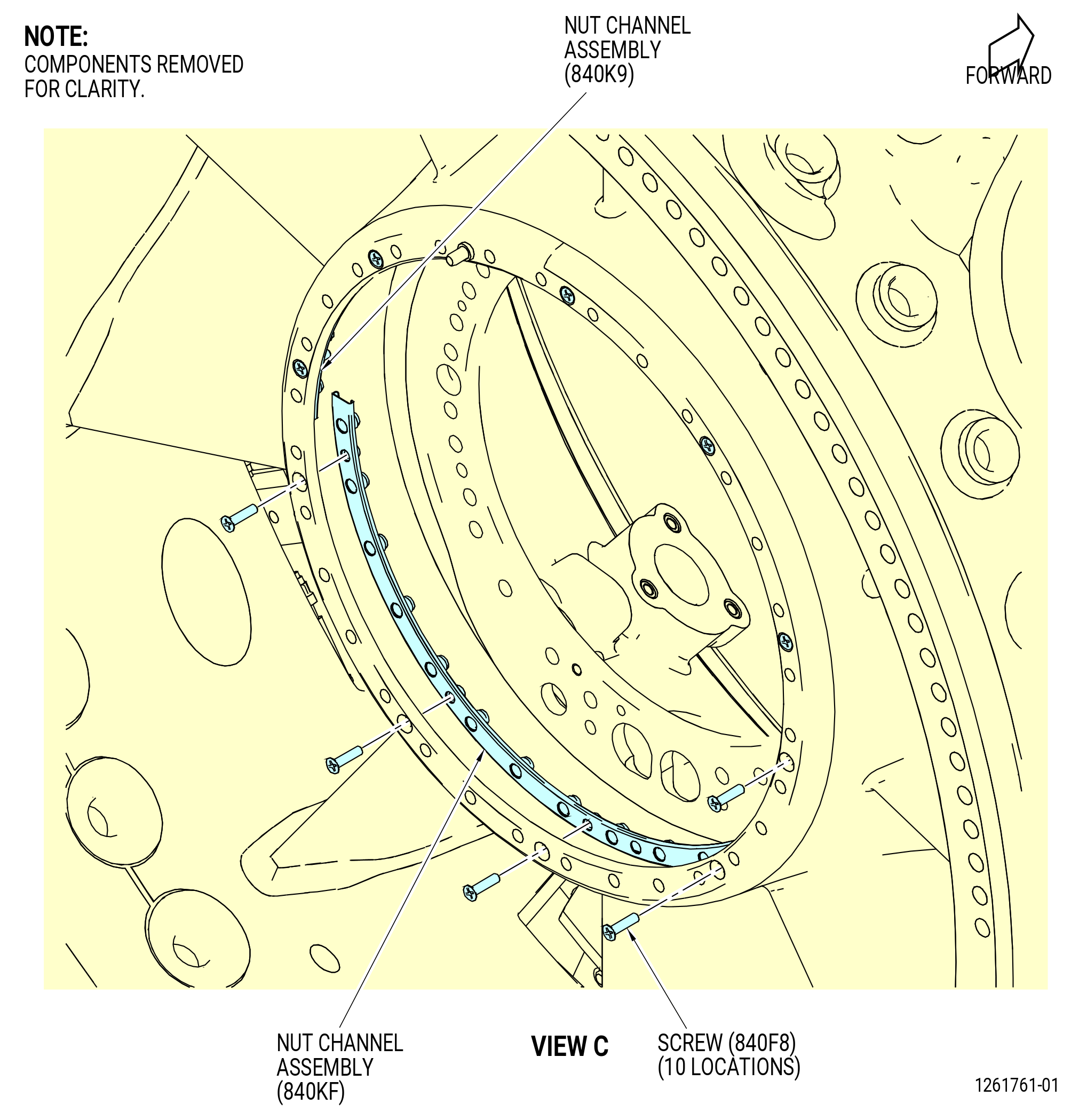
| U. | Install the gang channel nut assemblies (nut channel assembly) (01-480) (SIN 840K9) and (01-470) (SIN 840KF) to the FHF. Refer to Figure 1011 and do as follows: |
| (1) | Install each nut channel assembly on the FHF with the bolts (840F8). |
| (2) | Torque the bolts (840F8) to 49-57 lb. in (5.5-6.4 N.m). |
| Subtask 72-26-00-440-152 |
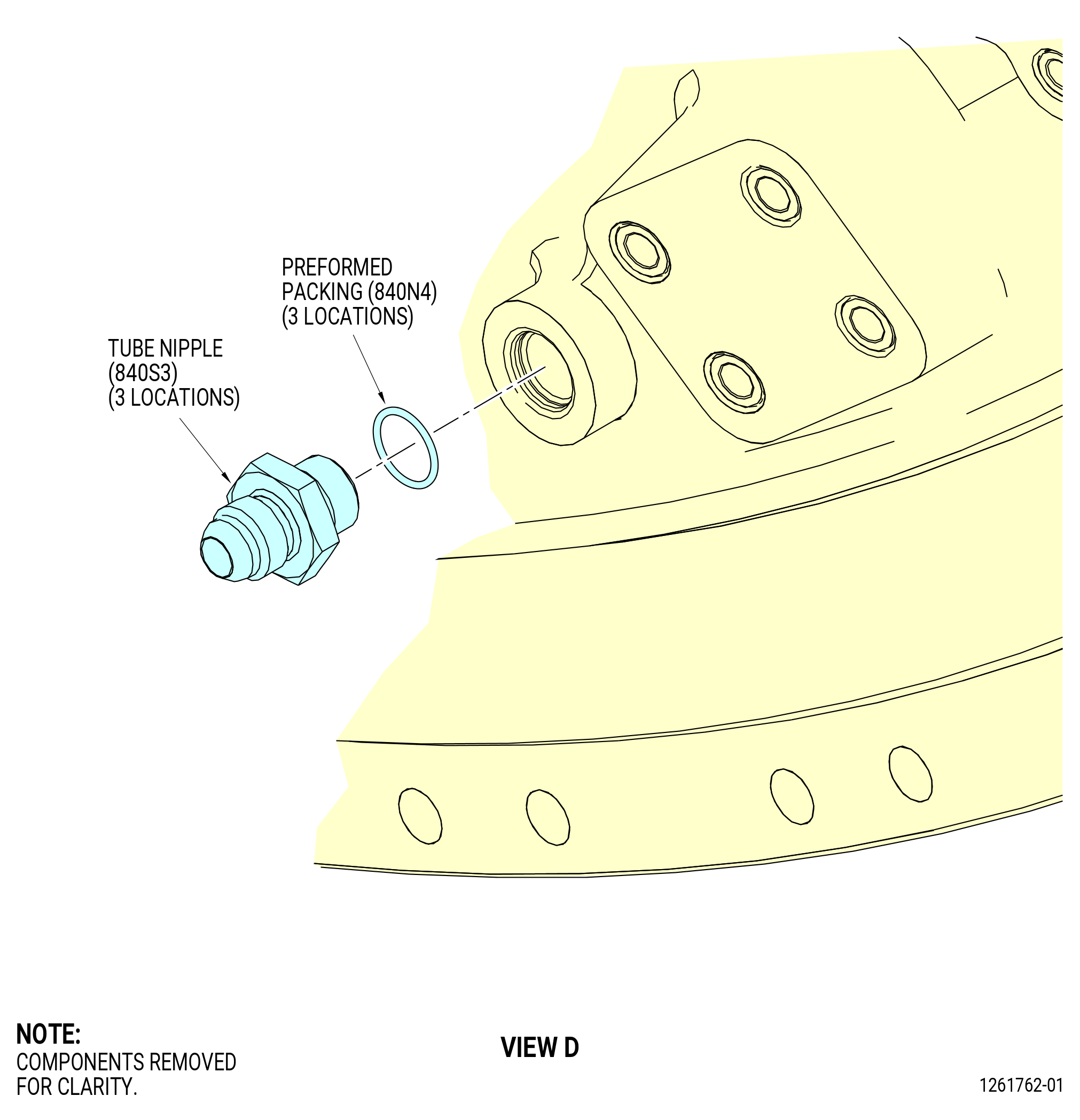
| V. | Install the tube nipples (01-430) (SIN 840S3) to the FHF. Refer to Figure 1011 and do as follows: |
| (1) | Install the preformed packing (01-440) (SIN 840N4) on the tube nipples. |
| Subtask 72-26-00-640-001 |
| WARNING: |
|
| CAUTION: |
|
| (2) | Apply C02-019 engine oil or C02-023 engine oil to the tube nipples. |
| Subtask 72-26-00-440-156 |
| (3) | Install the three tube nipples in the FHF. |
| (4) | Torque the tube nipples to 265-305 lb in. (29.9-34.5 N.m). |
| (5) | Install the protective caps on all the tube nipples. |
| Subtask 72-26-00-440-159 |
| * * * PRE SB 72-0083( ) |
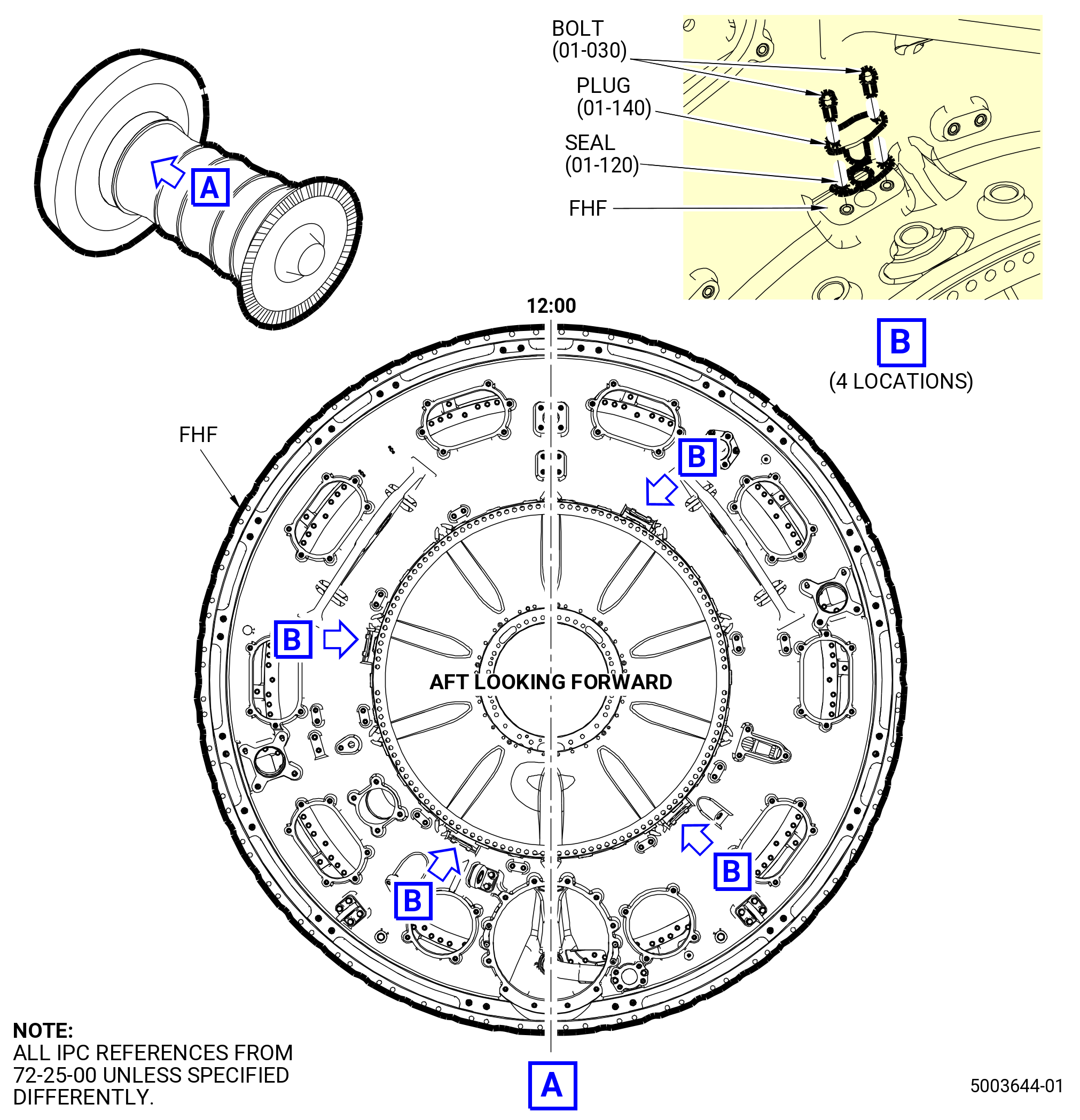
| W. | Install plugs in the core wash system ports. Refer to Figure 1013 and do as follows: |
| (1) | Install the four nozzle plugs (plug) (01-140 , 72-25-00) (SIN 78064) with water wash seals (seal) (01-120 , 72-25-00) (SIN 78070) and eight machine bolts (bolt) (01-030 , 72-25-00) (SIN 78020) in the core wash system ports at the 1:00, 4:30, 7:00, and 9:30 o’clock positions. |
| WARNING: |
|
| (a) | Apply C02-058 lubricant to the bolt threads. |
| (b) | Torque the bolts to 51-59 lb in. (5.8-6.7 N.m). |
| * * * END PRE SB 72-0083 |
| Subtask 72-26-00-440-160 |
| * * * SB 72-0083 |
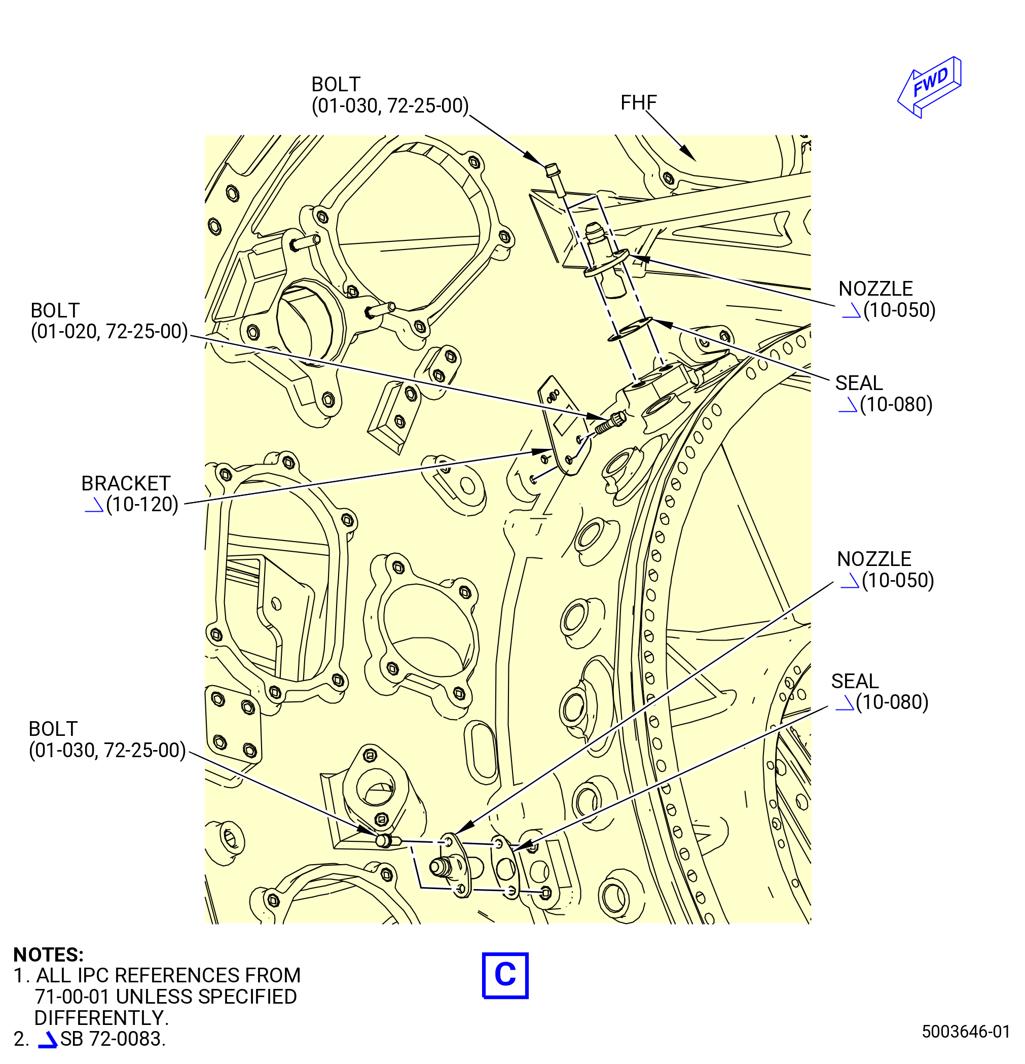
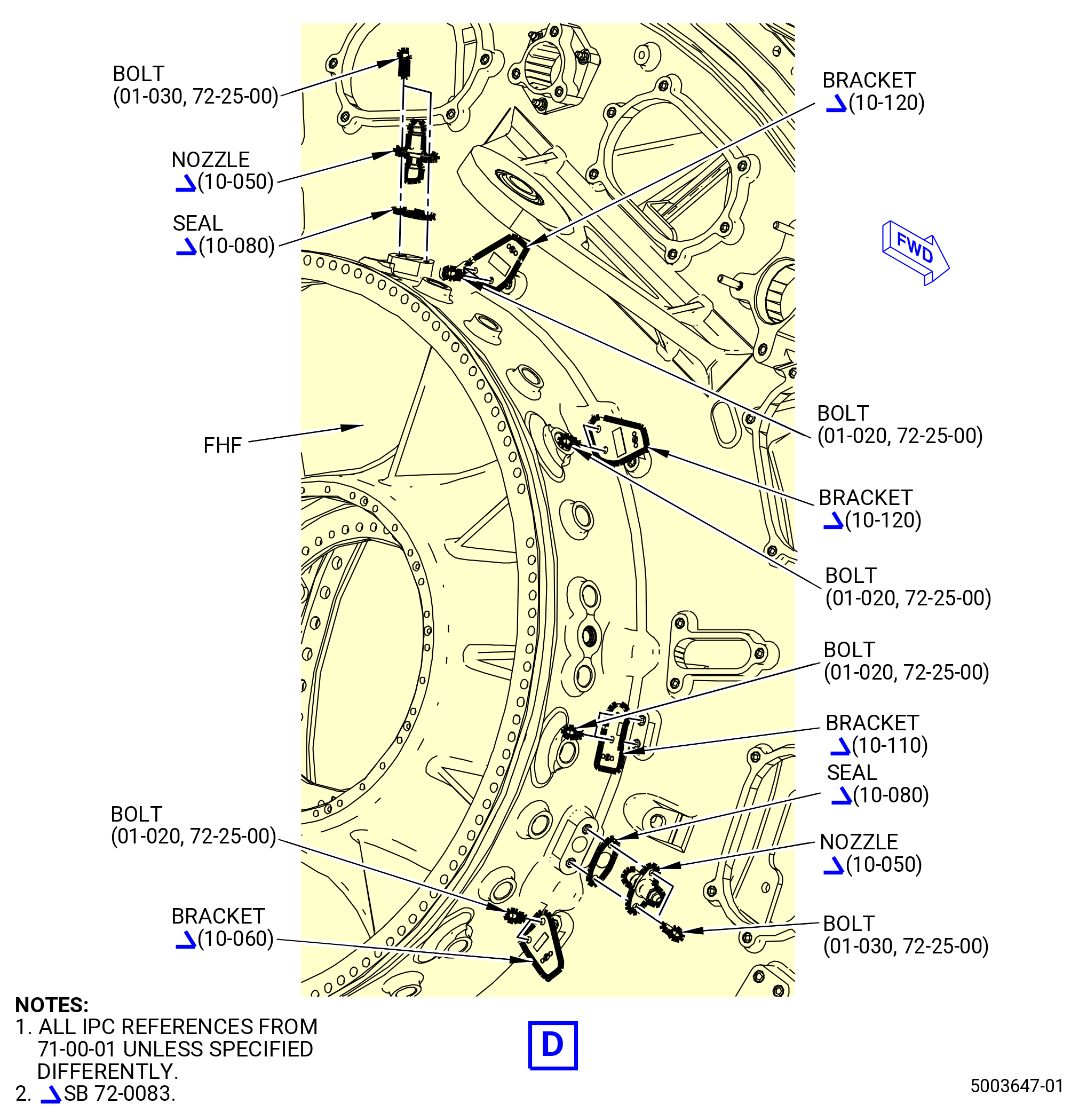
| W.A. | Install the core wash system nozzles and brackets on the FHF. Refer to Figure 1013A and do as follows: |
| (1) | Install the four core wash nozzles (nozzle) (10-050 , 71-00-01) (SIN 78005) with core wash seals (seal) (10-080 , 71-00-01) (SIN 78070) and bolts (01-030 , 72-25-00) (SIN 78020) in the core wash system ports at the 1:00, 4:30, 7:00, and 9:30 o’clock positions. |
| WARNING: |
|
| (a) | Apply C02-058 lubricant to the bolt threads. |
| (b) | Torque the bolts to 51-59 lb in. (5.8-6.7 N.m). |
| (2) | Install the brackets of the core wash system on the FHF as follows: |
| (a) | Install the three support brackets (bracket) (10-120 , 71-00-01) (SIN 78011) on the pads at the 1:30, 2:30, and 8:30 o’clock positions with bolts (01-020 , 72-25-00) (SIN 78022). |
| WARNING: |
|
| 1 | Apply C02-058 lubricant to the bolt threads. |
| 2 | Torque the bolts to 32-38 lb in. (3.6-4.3 N.m). |
| (b) | Install the support bracket (bracket) (10-110 , 71-00-01) (SIN 78010) on the pad at the 3:30 o’clock position with bolts (01-020 , 72-25-00) (SIN 78022). |
| WARNING: |
|
| 1 | Apply C02-058 lubricant to the bolt threads. |
| 2 | Torque the bolts to 32-38 lb in. (3.6-4.3 N.m). |
| (c) | Install the support bracket (bracket) (10-060 , 71-00-01) (SIN 78012) on the pad at 5:00 o’clock position with bolts (01-020 , 72-25-00) (SIN 78022). |
| WARNING: |
|
| 1 | Apply C02-058 lubricant to the bolt threads. |
| 2 | Torque the bolts to 32-38 lb in. (3.6-4.3 N.m). |
| * * * END SB 72-0083 |
| * * * PRE SB 72-0083 |
| * * * SB 72-0083 |
| Subtask 72-26-00-440-161 |
| * * * SB 72-0125( Sealing for Open Holes in the Fire Wall ) |
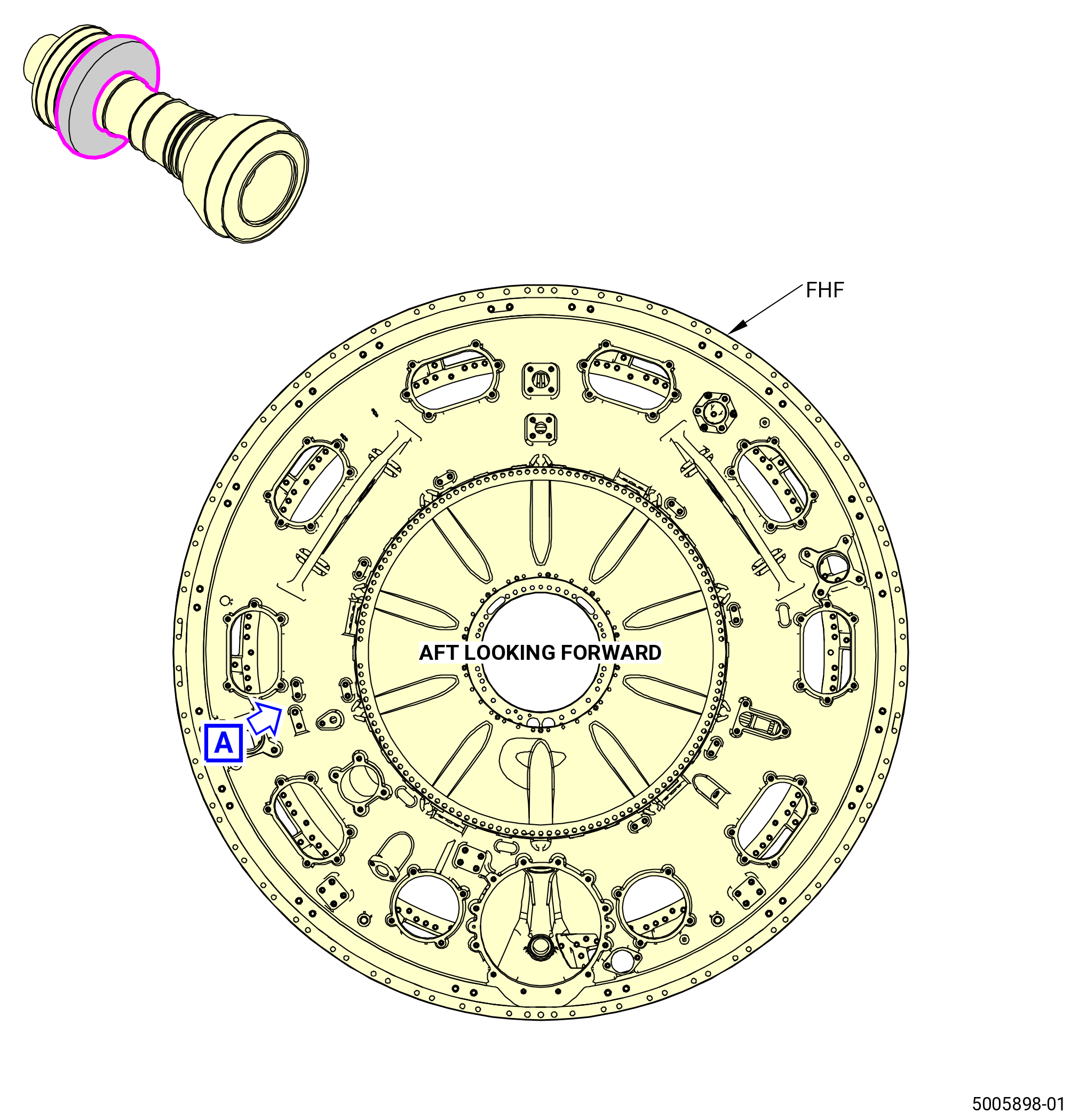
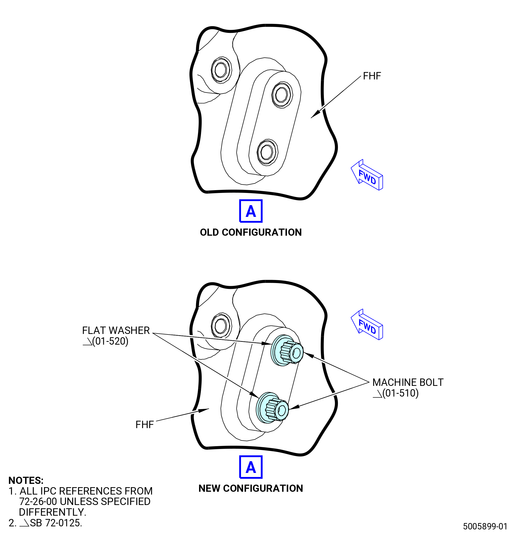
| X. | Install the machine bolts (01-510) (SIN 8402C) and flat washers (01-520) (SIN 8404C) on a boss on the aft side of the FHF. Refer to Figure 1014 and do as follows: |
| NOTE: |
|
| WARNING: |
|
| (1) | Clean the threads of the inserts on FHF with C04-035 isopropyl alcohol and a cotton swab near the 9:00 o'clock position. |
| (2) | Install the flat washers on the machine bolts. |
| WARNING: |
|
| (3) | Apply C02-058 lubricant to the threads of the two machine bolts. |
| (4) | Install the machine bolts and flat washers into the open inserts on the FHF. |
| (5) | Torque the machine bolts to 109-121 lb in. (12.3-13.7 N.m). |
| * * * END SB 72-0125 |
|
|
| Subtask 72-26-00-440-162 |
| * * * FOR 1B/P/G03.1B/P/G04 |
| * * * FOR 1B/P/G03.1B/P/G04 |
| * * * PRE SB 72-0156( Non PIP2 Configuration - Rake Capable ) |
| * * * SB 72-0111( Rake Capable FHF ) |
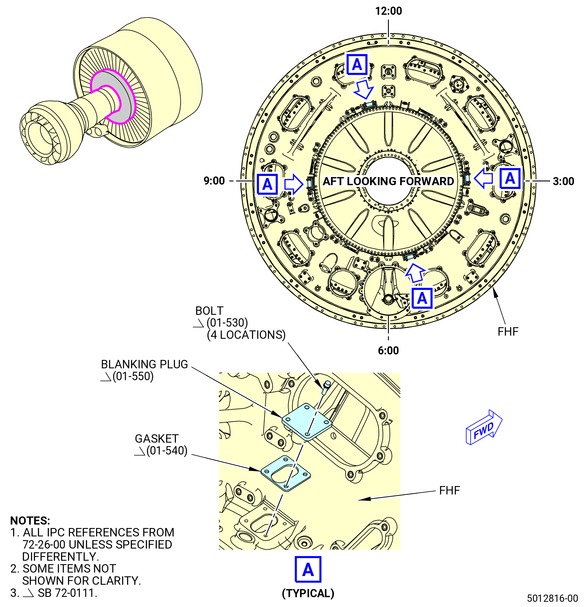
| Y. | Install the blanking plugs (01-550) (SIN 840S0) on the FHF. Refer to Figure 1015 and do as follows: |
| NOTE: |
|
| (1) | Install one gasket (01-540) (SIN 840N7) on each of the four blanking plugs. |
| WARNING: |
|
| (2) | Apply C02-058 lubricant to the threads of the 16 machine bolts (bolts) (01-530) (SIN 840FD). |
| (3) | Install the blanking plugs on the FHF with four bolts for each cover. Install plugs on the aft side of the FHF at the 3:00, 5:30, 9:00, and 11:00 o’clock positions. |
| (4) | Torque the bolts to 19-21 lb. in (2.1-2.4 N.m). |
| (5) | Safety the bolts with C10-071 safety wire or C10-143 safety cable. |
| * * * FOR 1B/P/G03.1B/P/G04 |
| * * * END SB 72-0111 |
| * * * END PRE SB 72-0156 |
| Subtask 72-26-00-440-163 |
| * * * FOR 1B/P2/G02 |
| * * * SB 72-0156( PIP 2 Configuration - Rake Capable ) |
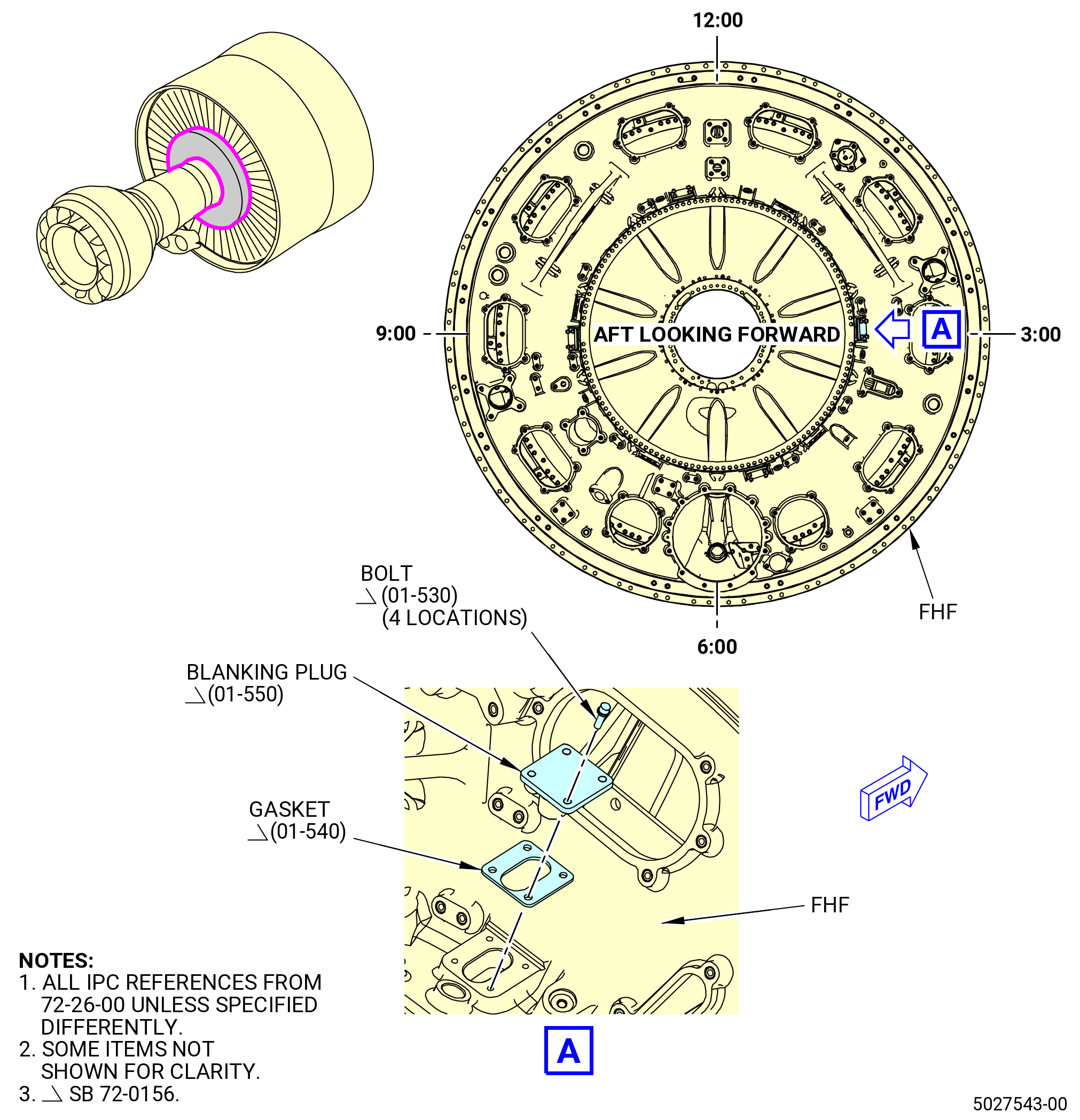
| Y.A. | Install the blanking plug (01-550) (SIN 840S0) on the FHF. Refer to Figure 1015 and do as follows: |
| (1) | Install the gasket (01-540) (SIN 840N7) on the blanking plug. |
| WARNING: |
|
| (2) | Apply C02-058 lubricant to the threads of the four bolts (01-530) (SIN 840FD). |
| (3) | Install the blanking plug on the aft side of the FHF at the 3:00 o’clock position with the bolts (01-530) (SIN 840FD). |
| (4) | Torque the bolts (01-530) (SIN 840FD) to 19 to 21 lb. in (2.1 to 2.4 Nm). |
| (5) | Safety the bolts (01-530) (SIN 840FD) with C10-071 safety wire or C10-143 safety cable. |
| * * * END SB 72-0156 |
| * * * FOR 1B/P/G03.1B/P/G04 |
|
| Subtask 72-26-00-440-153 |
| * * * FOR ALL |
| Z. | Continue with assembly of the fan hub module. Refer to TASK 72-25-00-440-801 (72-25-00, Assembly 001). |