| GENX-1B CLEANING,INSPECTION,AND REPAIR MANUAL | Dated: 09/13/2022 | |
| CIR 72-31-41 , INSPECTION 001 | ||
| HPC STAGE 1 BLISK - INSPECTION | ||
| GENX-1B CLEANING,INSPECTION,AND REPAIR MANUAL | Dated: 09/13/2022 | |
| CIR 72-31-41 , INSPECTION 001 | ||
| HPC STAGE 1 BLISK - INSPECTION | ||
| * * * FOR ALL |
| TASK 72-31-41-200-801 |
| 1 . | General. |
| A. | This procedure gives instructions to do an inspection of the HPC stage 1 blisk (blisk): |
| • |
|
| • |
|
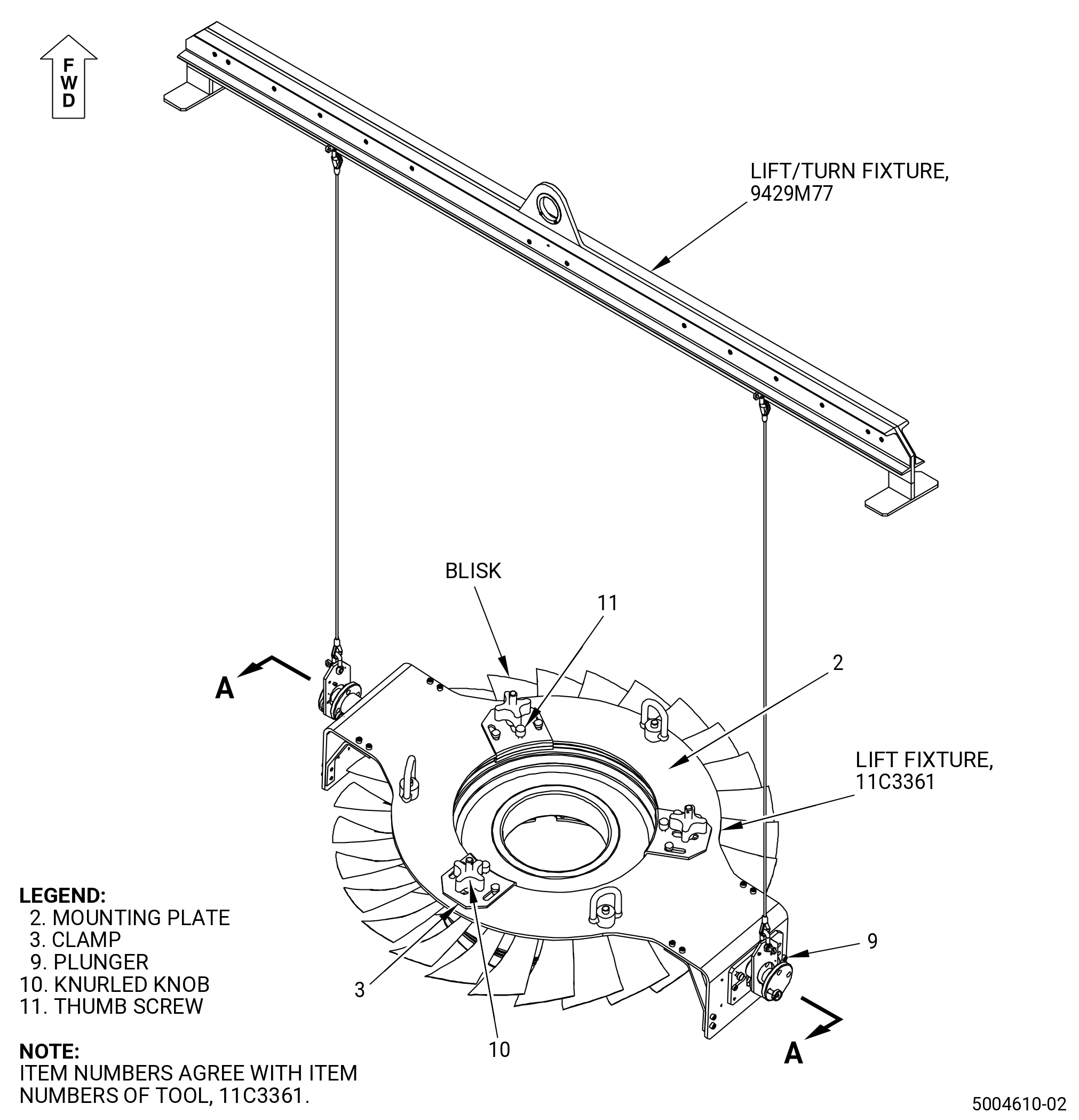
| B. | Use the 11C3361 lift fixture to position, lift, or turn the blisk in the working area. Refer to Subtask 72-31-41-420-002 (paragraph 3.) for instructions about installation and removal of the tool. |
| 2 . | Tools, Equipment, and Materials. |
| NOTE: |
|
| A. | Tools and Equipment. |
| (1) | Special Tools. |
|
| (2) | Standard Tools and Equipment. |
| (3) | Locally Manufactured Tools. None. |
| B. | Consumable Materials. None. |
| C. | Referenced Procedures. |
|
| D. | Expendable Parts. None. |
| 3 . | Tool Installation and Removal. |
| Subtask 72-31-41-420-002 |
| A. | Install the 11C3361 lift fixture. Refer to Figure 801 and do as follows: |
| (1) | Move the clamp (item 3) in, before the mounting plate (item 2) is installed on the blisk. |
| (2) | Install the mounting plate (item 2) on the forward flange of the blisk. |
| WARNING: |
|
| (3) | Move the clamp (item 3) out to lock on the lip of the blisk flange in the groove of the clamp (item 3). |
| (4) | Manually turn the thumb screw (item 11) to adjust it until there is no clearance between the clamp (item 3) jaw and the blisk flange. |
| (5) | Make sure that the thumb screw (item 11) is correctly installed in the pocket of the mounting plate (item 2). |
| (6) | Turn the knurled knob (item 10) to attach it the clamp (item 3). |
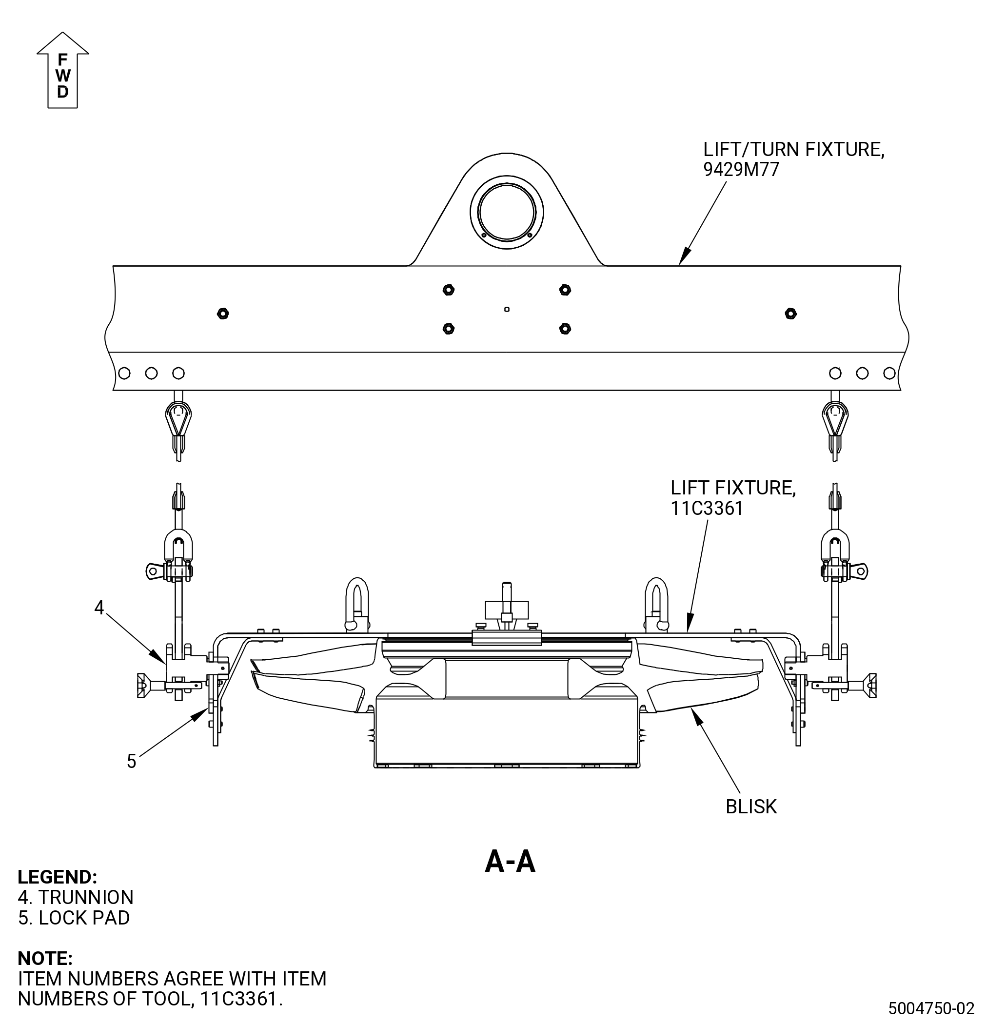
| (7) | Set the lock pad (item 5) on the mounting plate (item 2) as follows: |
| (a) | Move the trunnion (item 4) to the top position in the slot of the mounting plate (item 2). |
| (b) | Lock the trunnion (item 4) with the lock pad (item 5) in the top position. |
| (c) | Release the plunger (item 9) to move the lock pad (item 5). |
| (d) | Engage the plunger (item 9) in the related mounting plate (item 2) hole to keep the lock pad (item 5) in position. |
| (8) | Use the 9429M77 lift/turn fixture to move the 11C3361 lift fixture. |
| Subtask 72-31-41-020-002 |
| B. | Remove the 11C3361 lift fixture. Refer to Figure 801 and do as follows: |
| (1) | Loosen the knurled knob (item 10) to release the clamp (item 3). |
| (2) | Loosen the thumb screw (item 11) until is released from the pocket of the mounting plate (item 2). |
| (3) | Move the clamp (item 3) in to release the lip of the blisk flange out of the groove of the clamp (item 3). |
| (4) | Remove the mounting plate (item 2) from the blisk. |
| 4 . | Specific Inspection Procedure. |
| NOTE: |
|
| Subtask 72-31-41-230-001 |
| WARNING: |
|
| WARNING: |
|
| A. | Do a Class G non-aqueous wet developer fluorescent penetrant inspection of the blisk. Refer to TASK 70-32-02-230-001 (FLUORESCENT PENETRANT INSPECTION). |
| (1) | Make sure you do a careful inspection of the critical areas that follow: |
| • |
|
| • |
|
| • |
|
| • |
|
| • |
|
| • |
|
| • |
|
| (2) | Indications 0.015 inch (0.38 mm) or less are permitted. |
| Subtask 72-31-41-160-002 |
| B. | Do an eddy current inspection of the blisk bore surfaces as follows: |
| CAUTION: |
|
| (1) | Make sure the blisk is clean. Refer to 72-31-41-100-801 (72-31-41, Cleaning 001). |
| Subtask 72-31-41-250-001 |
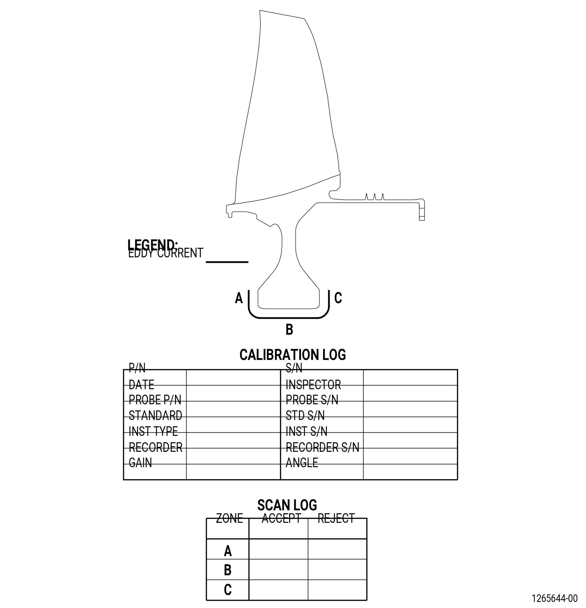
| (2) | Do an eddy current inspection of the blisk bore surfaces. Refer to TASK 70-32-10-250-003 (2 MHZ EDDY CURRENT INSPECTION OF BORES IN ROTATING ENGINE HARDWARE USING SYSTEMS UNDER COMPUTER, NUMERIC, OR ROBOTIC CONTROL) and Figure 802. |
| NOTE: |
|
| (a) | If you change the equipment or the procedure specified in this inspection, it can have an unwanted effect on the inspection results. Before you change the equipment or the procedure, write to: |
| GE Aircraft Engines, OTC |
| One Neumann Way, MD: Q8 |
| Cincinnati, Ohio 45215 |
| USA |
| (b) | The material is Ti 6-4. Use correction factors for calibration as necessary. Refer to TASK 70-32-10-250-003 (2 MHZ EDDY CURRENT INSPECTION OF BORES IN ROTATING ENGINE HARDWARE USING SYSTEMS UNDER COMPUTER, NUMERIC, OR ROBOTIC CONTROL). |
| (c) | Use the GE-FQAP-428inspection kit to do an inspection of the bore zones shown in Figure 802. |
| (d) | Examine the inspection results. Use the limits that follow: |
| 1 | The eddy current inspection limit is 1500 mV. |
| 2 | If the amplitude of an indication is more than 1500 mV, the fan disk is not serviceable. |
| (e) | Complete the eddy current data sheets. |
| (f) | Make sure you complete all records during the eddy current inspection. Keep all records made during the inspection. |
| 5 . | Visual Inspection. |
| Refer to Figure 803. |
| Subtask 72-31-41-220-001 |
| A. | Do an inspection of all areas for: |
| (1) | Cracks: |
| Maximum serviceable limit: |
|
| Repair method: |
|
| Subtask 72-31-41-220-002 |
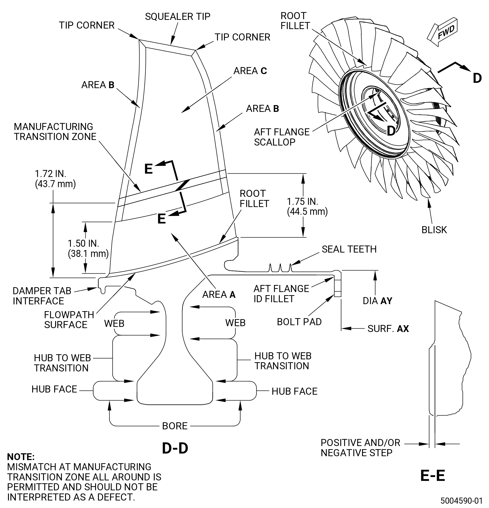
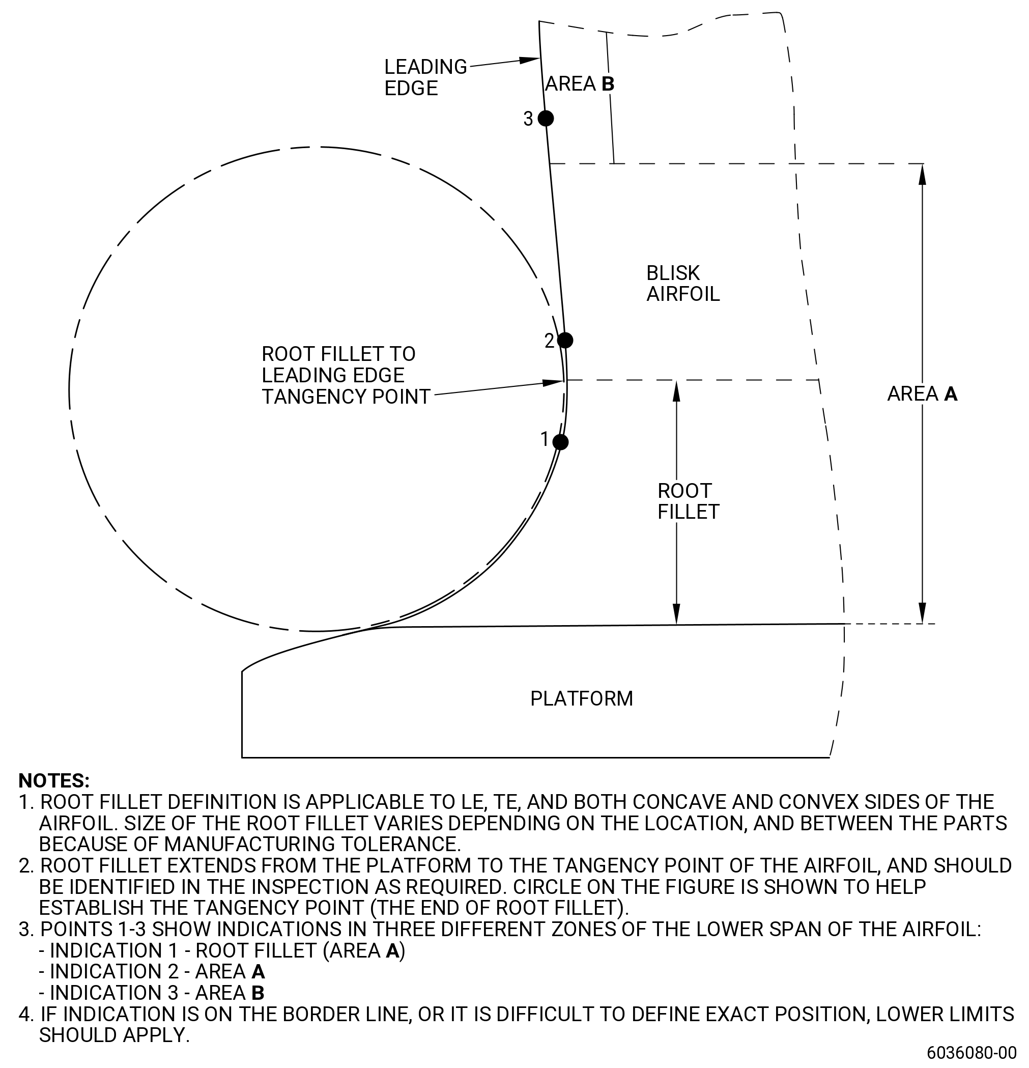
| B. | Do an inspection of area A (critical) for. Refer to Figure 803 and Figure 804. |
| (1) | Nicks, dents, and pits in the root fillet: |
| Maximum serviceable limit: |
|
| Repair method: |
|
| Subtask 72-31-41-220-043 |
| (2) | Scratches in the root fillet: |
| Maximum serviceable limit: |
|
| Repair method: |
|
| Subtask 72-31-41-220-044 |
| (3) | Tears and cracks in the fillet: |
| Maximum serviceable limit: |
|
| Repair method: |
|
| Subtask 72-31-41-220-045 |
| (4) | Nicks, dents, and pits on the leading and trailing edges: |
| Maximum serviceable limit: |
|
| Repair method: |
|
| Subtask 72-31-41-220-046 |
| (5) | Tears and cracks on the leading and trailing edges: |
| Maximum serviceable limit: |
|
| Repair method: |
|
| Subtask 72-31-41-220-047 |
| (6) | Deposits on the leading and trailing edges: |
| Maximum serviceable limit: |
|
| Repair method: |
|
| Subtask 72-31-41-220-048 |
| (7) | Scratches in area A above the root fillet: |
| Maximum serviceable limit: |
|
| Repair method: |
|
| Subtask 72-31-41-220-049 |
| (8) | Bulge deformation on the leading and trailing edges: |
| Maximum serviceable limit: |
|
| Repair method: |
|
| Subtask 72-31-41-220-003 |
| C. | Do an inspection of area B (leading and trailing edges) on the blisk blade for: |
| (1) | Nicks: |
| Maximum serviceable limit: |
|
| Repair method: |
|
| Subtask 72-31-41-220-004 |
| NOTE: |
|
| (2) | Dents and pits: |
| Maximum serviceable limit: |
|
| Repair method: |
|
| Subtask 72-31-41-220-005 |
| (3) | Scratches and gouges: |
| Maximum serviceable limit: |
|
| Repair method: |
|
| Subtask 72-31-41-220-006 |
| (4) | Deposits: |
| Maximum serviceable limit: |
|
| Repair method: |
|
| Subtask 72-31-41-220-007 |
| (5) | Metal splatter deposits: |
| Maximum serviceable limit: |
|
| Repair method: |
|
| Subtask 72-31-41-220-008 |
| (6) | Erosion on the leading edge: |
| Maximum serviceable limit: |
|
| Repair method: |
|
| Subtask 72-31-41-220-009 |
| (7) | Cracks: |
| Maximum serviceable limit: |
|
| Repair method: |
|
| Subtask 72-31-41-220-010 |
| (8) | Bulge deformation: |
| Maximum serviceable limit: |
|
| Repair method: |
|
| Subtask 72-31-41-220-066 |
| (9) | Tears: |
| Maximum serviceable limit: |
|
| Repair method: |
|
| Subtask 72-31-41-220-011 |
| D. | Do an inspection of area C (concave and convex airfoil contour surfaces) of the blisk blade for: |
| (1) | Nicks, dents, and pits: |
| Maximum serviceable limit: |
|
| Repair method: |
|
| Subtask 72-31-41-220-012 |
| (2) | Scratches: |
| Maximum serviceable limit: |
|
| Repair method: |
|
| Subtask 72-31-41-220-013 |
| (3) | Metal splatter deposits: |
| Maximum serviceable limit: |
|
| Repair method: |
|
| Subtask 72-31-41-220-014 |
| E. | Do an inspection of the airfoil for: |
| (1) | Bent airfoil: |
| Maximum serviceable limit: |
|
| Repair method: |
|
| Subtask 72-31-41-220-015 |
| F. | Do an inspection of the flowpath surface of the blisk (does not include root fillet) for: |
| (1) | Nicks, dents, pits, and scratches: |
| Maximum serviceable limit: |
|
| Repair method: |
|
| Subtask 72-31-41-220-016 |
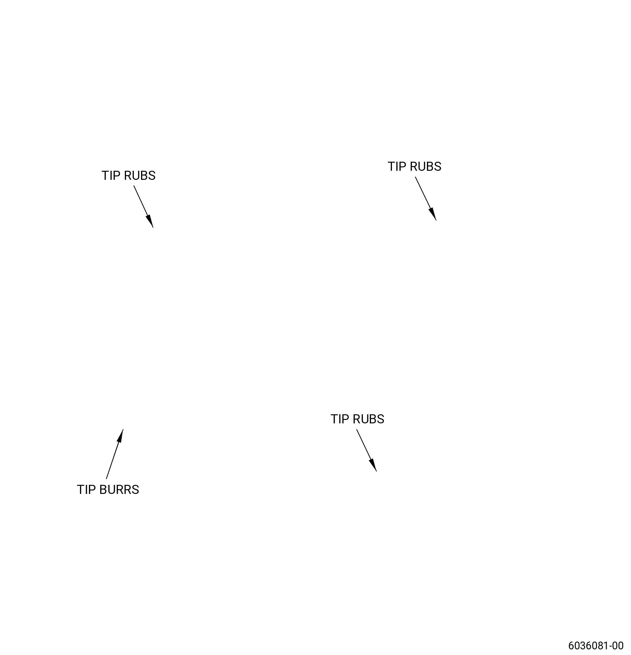
| G. | Do an inspection of the squealer tip of the blisk blade for. Refer to Figure 805. |
| (1) | Cracks: |
| Maximum serviceable limit: |
|
| Repair method: |
|
| Subtask 72-31-41-220-051 |
| (2) | Nicks and dents: |
| Maximum serviceable limit: |
|
| Repair method: |
|
| Subtask 72-31-41-220-017 |
| (3) | Tip rub: |
| NOTE: |
|
| Maximum serviceable limit: |
|
| Repair method: |
|
| Subtask 72-31-41-220-018 |
| (4) | Burrs and high metal: |
| NOTE: |
|
| Maximum serviceable limit: |
|
| Maximum repairable limit: |
|
| Repair method: |
|
| Subtask 72-31-41-220-019 |
| (5) | Heat discoloration caused by tip rub: |
| NOTE: |
|
| NOTE: |
|
| NOTE: |
|
| NOTE: |
|
| Maximum serviceable limit: |
|
| Repair method: |
|
| Subtask 72-31-41-220-020 |
| (6) | Deposits: |
| Maximum serviceable limit: |
|
| Repair method: |
|
| Subtask 72-31-41-220-021 |
| (7) | Bending and curling of the squealer tip: |
| Maximum serviceable limit: |
|
| Repair method: |
|
| Subtask 72-31-41-220-022 |
| (8) | Erosion: |
| Maximum serviceable limit: |
|
| Maximum repairable limit: |
|
| Repair method: |
|
| Subtask 72-31-41-220-024 |
| H. | Do an inspection of the tip corners of the blisk for: |
| NOTE: |
|
| * * * PRE SB 72-0013( Old Design for the Stage 1 Blisk ) |
| (1) | Tip corners that are missing on leading edge: |
| Maximum serviceable limit: |
|
| Repair method: |
|
| * * * END PRE SB 72-0013 |
| Subtask 72-31-41-220-067 |
| * * * SB 72-0013( New Design for the Stage 1 Blisk ) |
| (1).A. | Missing leading edge tip corners: |
| Maximum serviceable limit: |
|
| Maximum serviceable limit: |
|
| Repair method: |
|
| * * * END SB 72-0013 |
| Subtask 72-31-41-220-068 |
| * * * PRE SB 72-0013( Old Design for the Stage 1 Blisk ) |
| (2) | Tip corners that are missing on trailing edge: |
| Maximum serviceable limit: |
|
| Repair method: |
|
| * * * END PRE SB 72-0013 |
| Subtask 72-31-41-220-070 |
| * * * SB 72-0013( New Design for the Stage 1 Blisk ) |
| (2).A. | Missing trailing edge tip corners: |
| Maximum serviceable limit: |
|
| Repair method: |
|
| * * * END SB 72-0013 |
| Subtask 72-31-41-220-069 |
| (3) | All other damage: |
| Maximum serviceable limit: |
|
| Maximum repairable limit: |
|
| Repair method: |
|
| Subtask 72-31-41-220-025 |
| I. | Do an inspection of the flange for: |
| (1) | Fretting or galling on bolt pads: |
| Maximum serviceable limit: |
|
| Repair method: |
|
| Subtask 72-31-41-220-026 |
| (2) | Nicks, dents, pits, and scratches on bolt pads: |
| Maximum serviceable limit: |
|
| Repair method: |
|
| Subtask 72-31-41-220-027 |
| (3) | Fretting, galling, and wear on diameter AY: |
| Maximum serviceable limit: |
|
| Repair method: |
|
| Subtask 72-31-41-220-028 |
| (4) | Nicks, dents, pits, and scratches on diameter AY: |
| Maximum serviceable limit: |
|
| Repair method: |
|
| Subtask 72-31-41-220-052 |
| (5) | Nicks, dents, pits, and scratches on surface AX: |
| Maximum serviceable limit: |
|
| Repair method: |
|
| Subtask 72-31-41-220-083 |
| (6) | Fretting, galling, and wear on surface AX: |
| Maximum serviceable limit: |
|
| Repair method: |
|
| Subtask 72-31-41-220-029 |
| J. | Do an inspection of the boltholes for: |
| (1) | Nicks, dents, pits, and scratches on the inner diameter: |
| Maximum serviceable limit: |
|
| Repair method: |
|
| Subtask 72-31-41-220-030 |
| (2) | Nicks, dents, pits, and scratches on the chamfers: |
| Maximum serviceable limit: |
|
| Repair method: |
|
| Subtask 72-31-41-220-031 |
| (3) | Fretting, galling, or wear: |
| Maximum serviceable limit: |
|
| Repair method: |
|
| Subtask 72-31-41-220-053 |
| K. | Do an inspection of the aft flange scallop (8 locations) for: |
| (1) | Nicks, dents, pits, or scratches on the scallop surface: |
| Maximum serviceable limit: |
|
| Repair method: |
|
| Subtask 72-31-41-220-054 |
| (2) | Nicks, dents, pits, or scratches on the scallop chamfers (forward and aft sides): |
| Maximum serviceable limit: |
|
| Repair method: |
|
| Subtask 72-31-41-220-032 |
| L. | Do an inspection of the disk bore, hub faces, and web for: |
| (1) | Nicks, dents, pits, or scratches on the disk bore: |
| Maximum serviceable limit: |
|
| Repair method: |
|
| Subtask 72-31-41-220-076 |
| (2) | Nicks, dents, pits, or scratches on hub faces: |
| Maximum serviceable limit: |
|
| Repair method: |
|
| Subtask 72-31-41-220-077 |
| (3) | Nicks, dents, pits, or scratches on webs and web transitions: |
| Maximum serviceable limit: |
|
| Repair method: |
|
| Subtask 72-31-41-220-055 |
| M. | Do an inspection of the damper interface for: |
| (1) | Nicks, dents, pits, or scratches: |
| Maximum serviceable limit: |
|
| Repair method: |
|
| Subtask 72-31-41-220-056 |
| (2) | Fretting, galling, and wear: |
| Maximum serviceable limit: |
|
| Repair method: |
|
| Subtask 72-31-41-220-057 |
| N. | Do an inspection of the seal teeth for: |
| (1) | Nicks, dents, pits, or scratches: |
| Maximum serviceable limit: |
|
| Maximum repairable limit: |
|
| Repair method: |
|
| Subtask 72-31-41-220-058 |
| (2) | Seal teeth wear: |
| Maximum serviceable limit: |
|
| Repair method: |
|
| Subtask 72-31-41-220-078 |
| O. | Do an inspection of the aft flange ID fillet for: |
| (1) | Marks, nicks, dents, or scratches: |
| Maximum serviceable limit: |
|
| Repair method: |
|
| Subtask 72-31-41-220-060 |
| P. | Do an inspection of all other areas on the disk portion of the part (does not include airfoils or flowpath) for: |
| (1) | Nicks, dents, pits, or scratches: |
| Maximum serviceable limit: |
|
| Repair method: |
|
| 6 . | Special Dimensional Inspection. |
| Subtask 72-31-41-220-071 |
| A. | Deleted. |
| Subtask 72-31-41-220-072 |
| B. | Measure all dimensions with surface AX held flat within 0.001 inch (0.03 mm) and diameter AY restrained round within 0.001 inch (0.03 mm) unless specified differently. |
| Subtask 72-31-41-220-033 |
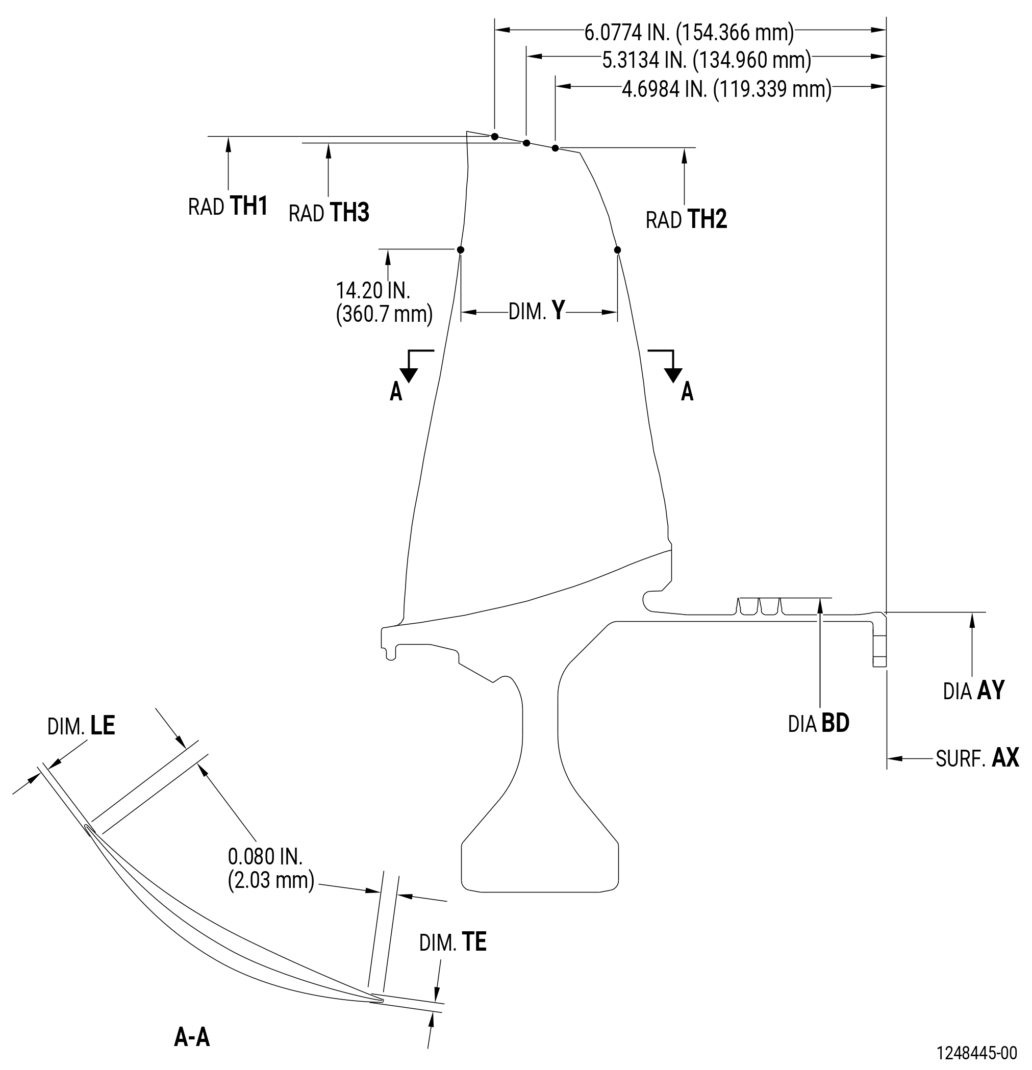
| C. | Measure the dimensions that follow: |
| (1) | Dimension Y: |
| NOTE: |
|
| Minimum serviceable limit: |
|
| Repair method: |
|
| Subtask 72-31-41-220-034 |
| (2) | Dimension LE of the leading edge thickness |
| NOTE: |
|
| Minimum serviceable limit: |
|
| Repair method: |
|
| Subtask 72-31-41-220-035 |
| (3) | Dimension TE of the trailing edge thickness: |
| NOTE: |
|
| Minimum serviceable limit: |
|
| Repair method: |
|
| Subtask 72-31-41-220-036 |
| (4) | Diameter AY: |
| Minimum serviceable limit: |
|
| Maximum serviceable limit: |
|
| Repair method: |
|
| Subtask 72-31-41-220-037 |
| (5) | Roundness of diameter AY: |
| Maximum serviceable limit: |
|
| Repair method: |
|
| Subtask 72-31-41-220-038 |
| (6) | Flatness of surface AX in free state: |
| Maximum serviceable limit: |
|
| Repair method: |
|
| Subtask 72-31-41-220-039 |
| (7) | Seal tooth diameter BD: |
| NOTE: |
|
| Minimum serviceable limit: |
|
| Maximum serviceable limit: |
|
| Repair method: |
|
| Subtask 72-31-41-220-041 |
| * * * PRE SB 72-0157( HPC Rotor Hardware Release for Non PIP 2 Engines ) |
| D. | Do an inspection of the height of the blade for: |
| NOTE: |
|
| (1) | Radius TH1 in relation with surface AX and diameter AY: |
| Minimum serviceable limit: |
|
| Repair method: |
|
| * * * END PRE SB 72-0157 |
| Subtask 72-31-41-220-084 |
| * * * SB 72-0157 |
| (1).A. | Radius TH1 in relation with surface AX and diameter AY: |
| Minimum serviceable limit: |
|
| Repair method: |
|
| * * * END SB 72-0157 |
| Subtask 72-31-41-220-042 |
| * * * PRE SB 72-0157( HPC Rotor Hardware Release for Non PIP 2 Engines ) |
| (2) | Radius TH2 in relation with surface AX and diameter AY: |
| Minimum serviceable limit: |
|
| Repair method: |
|
| * * * END PRE SB 72-0157 |
| Subtask 72-31-41-220-085 |
| * * * SB 72-0157 |
| (2).A. | Radius TH2 in relation with surface AX and diameter AY: |
| Minimum serviceable limit: |
|
| Repair method: |
|
| * * * END SB 72-0157 |
| Subtask 72-31-41-220-061 |
| * * * PRE SB 72-0157( HPC Rotor Hardware Release for Non PIP 2 Engines ) |
| (3) | Radius TH3 in relation with surface AX and diameter AY: |
| Minimum serviceable limit: |
|
| Repair method: |
|
| * * * END PRE SB 72-0157 |
| Subtask 72-31-41-220-086 |
| * * * SB 72-0157 |
| (3).A. | Radius TH3 in relation with surface AX and diameter AY: |
| Minimum serviceable limit: |
|
| Repair method: |
|
| * * * END SB 72-0157 |