| GENX-1B CLEANING,INSPECTION,AND REPAIR MANUAL | Dated: 11/30/2023 | |
| CIR 72-31-44 , INSPECTION 001 | ||
| HPC STAGE 5 BLISK - INSPECTION | ||
| GENX-1B CLEANING,INSPECTION,AND REPAIR MANUAL | Dated: 11/30/2023 | |
| CIR 72-31-44 , INSPECTION 001 | ||
| HPC STAGE 5 BLISK - INSPECTION | ||
| * * * FOR ALL |
| TASK 72-31-44-200-801 |
| 1 . | General. |
| A. | This procedure gives instructions to do an inspection of the HPC stage 5 (blisk). Refer to Figure 803. |
| • |
|
| • |
|
| • |
|
| • |
|
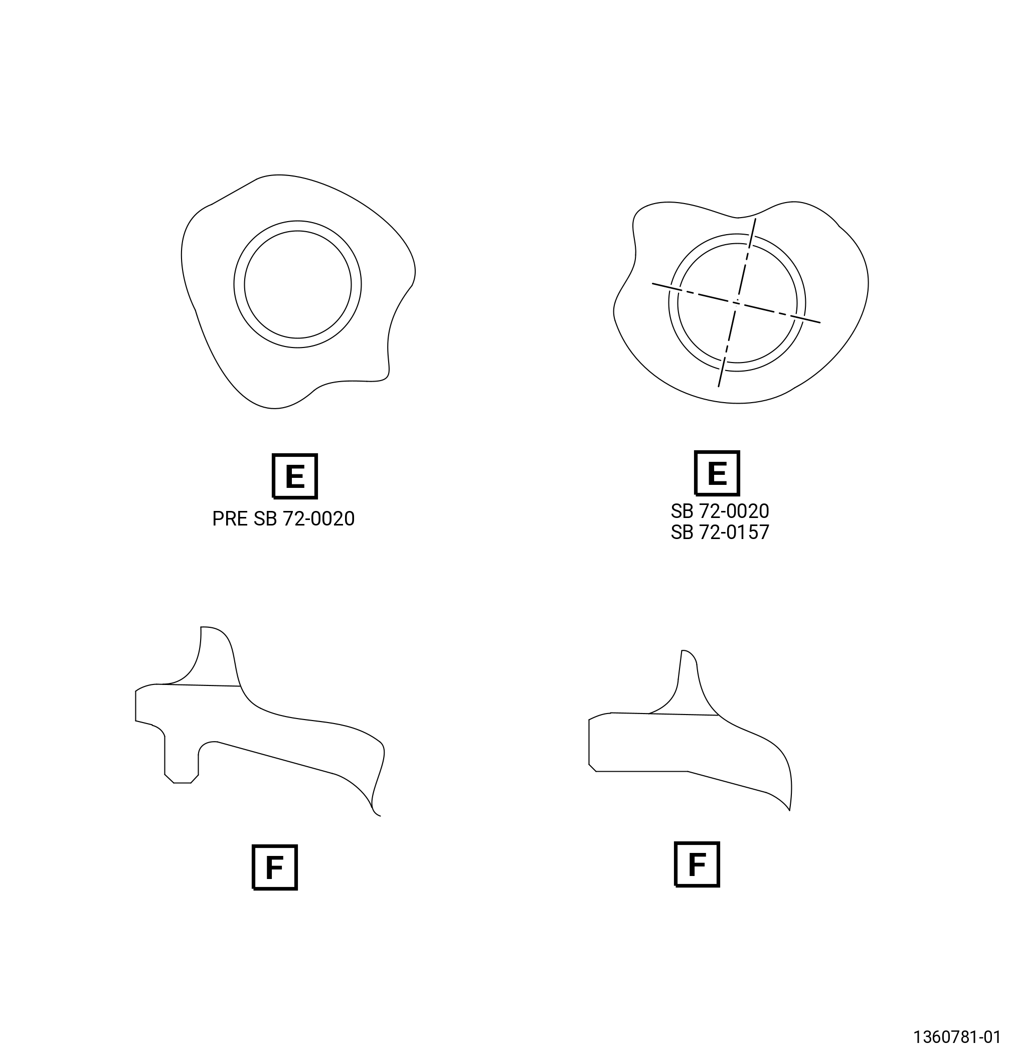
| B. | There are several configurations of the stage 5 blisk. The PRE SB 72-0020 blisk has an oval bolthole and a forward damper tab. The SB 72-0020 blisk has a rounded bolthole and does not have a forward damper tab. The SB 72-0157 blisk is GEnx-1B PIP2 capable. The SB 72-0492 has machined airfoil tip, to repair part with tip discoloration. |
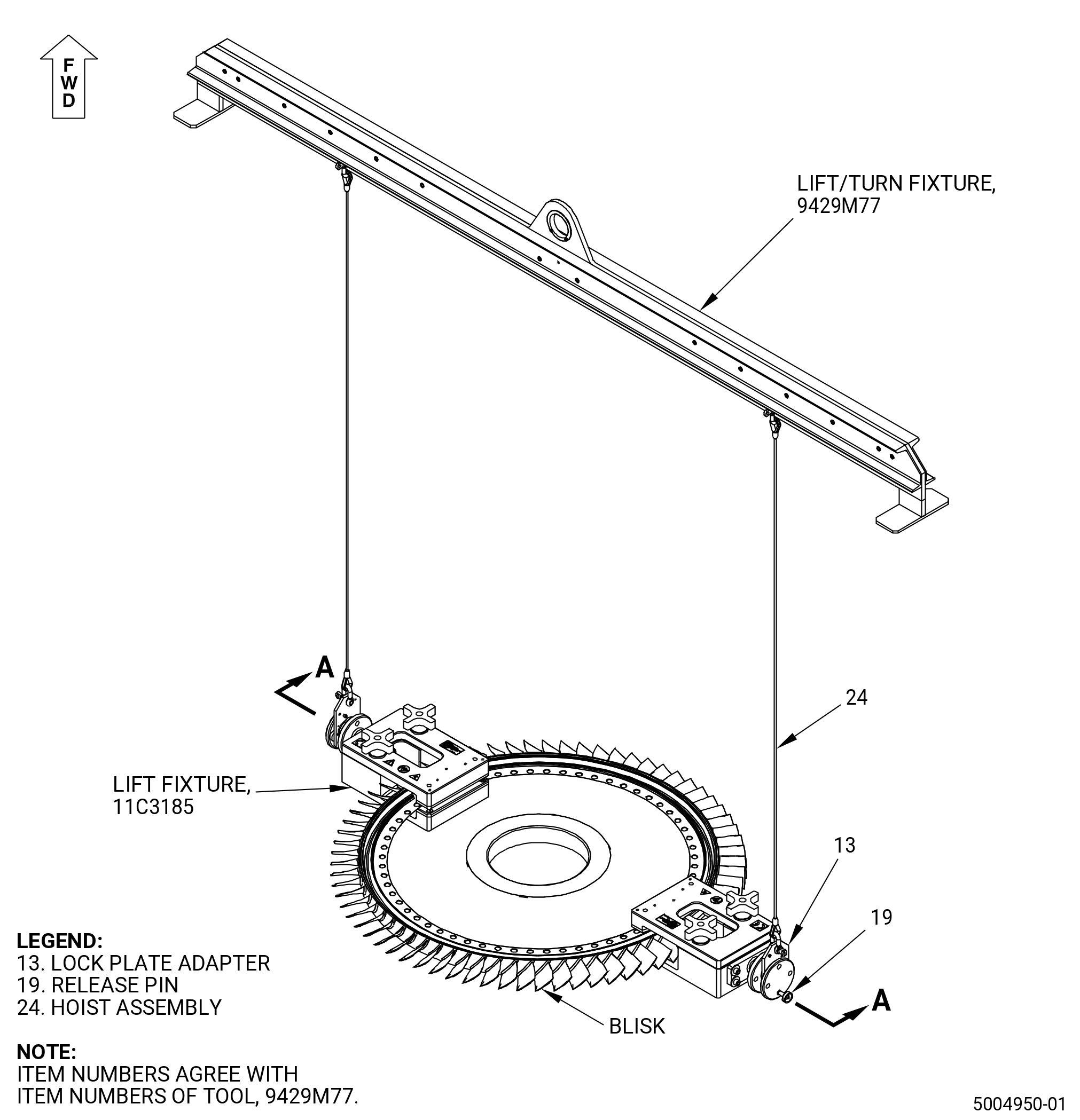
| C. | Use the 11C3185 lift fixture to position, lift, or turn the blisk in the working area. Refer to Subtask 72-31-44-420-002 (paragraph 3.A.) for instructions about installation and removal of the tool. |
| 2 . | Tools, Equipment, and Materials. |
| NOTE: |
|
| A. | Tools and Equipment. |
| (1) | Special Tools. |
| (2) | Standard Tools and Equipment. |
|
| NOTE: |
|
| (3) | Locally Manufactured Tools. None. |
| B. | Consumable Materials. None. |
| C. | Referenced Procedures. |
|
| D. | Expendable Parts. None. |
| 3 . | Tool Installation and Removal. |
| Subtask 72-31-44-420-002 |
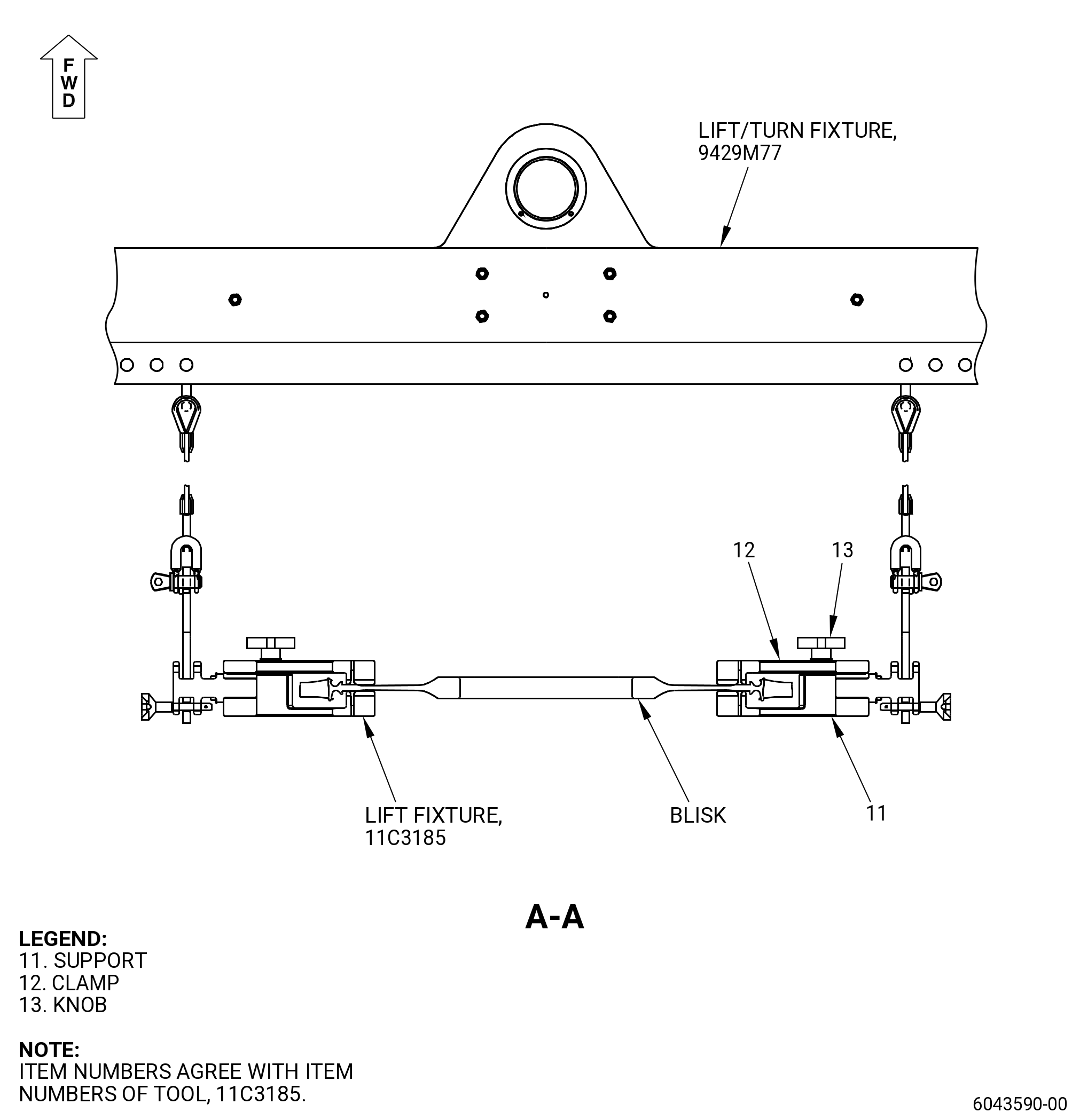
| A. | Install the 11C3185 lift fixture. Refer to Figure 801 and do as follows: |
| (1) | Put the support (item 11) below the forward side of the blisk. |
| (2) | Put the clamp (item 12) on the blisk and align it with the support (item 11). Use the holes on the two items as a reference. |
| (3) | Attach firmly the clamp (item 12) against the support (item 11) with the knob (item 13). |
| (4) | Install the other support (item 11) and clamp (item 12) assembly 180 degrees apart from the first assembly to make sure that the blisk is balanced when it is lifted. |
| (5) | Attach firmly the other clamp (item 12) against the support (item 11) with the knob (item 13). |
| (6) | Install the 9429M77 lift/turn fixture on the 11C3185 lift fixture. |
| (7) | Put the lock plate adapter (item 13) on the 11C3185 lift fixture and attach it with the release pin (item 19). |
| (8) | Use the 9429M77 lift/turn fixture to move the 11C3185 lift fixture. |
| Subtask 72-31-44-020-002 |
| B. | Remove the 11C3185 lift fixture. Refer to Figure 801 and do as follows: |
| (1) | Remove the 9429M77 lift/turn fixture from the 11C3185 lift fixture as follows: |
| (a) | Remove the release pin (item 19) and lock plate adapter (item 13) from the 11C3185 lift fixture. |
| (2) | Loosen the knob (item 13). |
| (3) | Remove the supports (item 11) and clamps (item 12) from the blisk. |
| 4 . | Specific Inspection Procedure. |
| NOTE: |
|
| Subtask 72-31-44-230-001 |
| WARNING: |
|
| WARNING: |
|
| A. | Do a Class G fluorescent penetrant inspection of the blisk. Refer to TASK 70-32-02-230-001 (FLUORESCENT PENETRANT INSPECTION). |
| (1) | Make sure you do a careful inspection of the critical area that follows: |
| • |
|
| • |
|
| • |
|
| • |
|
| (2) | Indications 0.015 inch (0.38 mm) or less are permitted. |
| Subtask 72-31-44-230-002 |
| WARNING: |
|
| WARNING: |
|
| B. | Do a Class G non-aqueous wet developer (NAWD) fluorescent penetrant inspection of the bolt holes. Refer to TASK 70-32-02-230-001 (FLUORESCENT PENETRANT INSPECTION). |
| Subtask 72-31-44-250-001 |
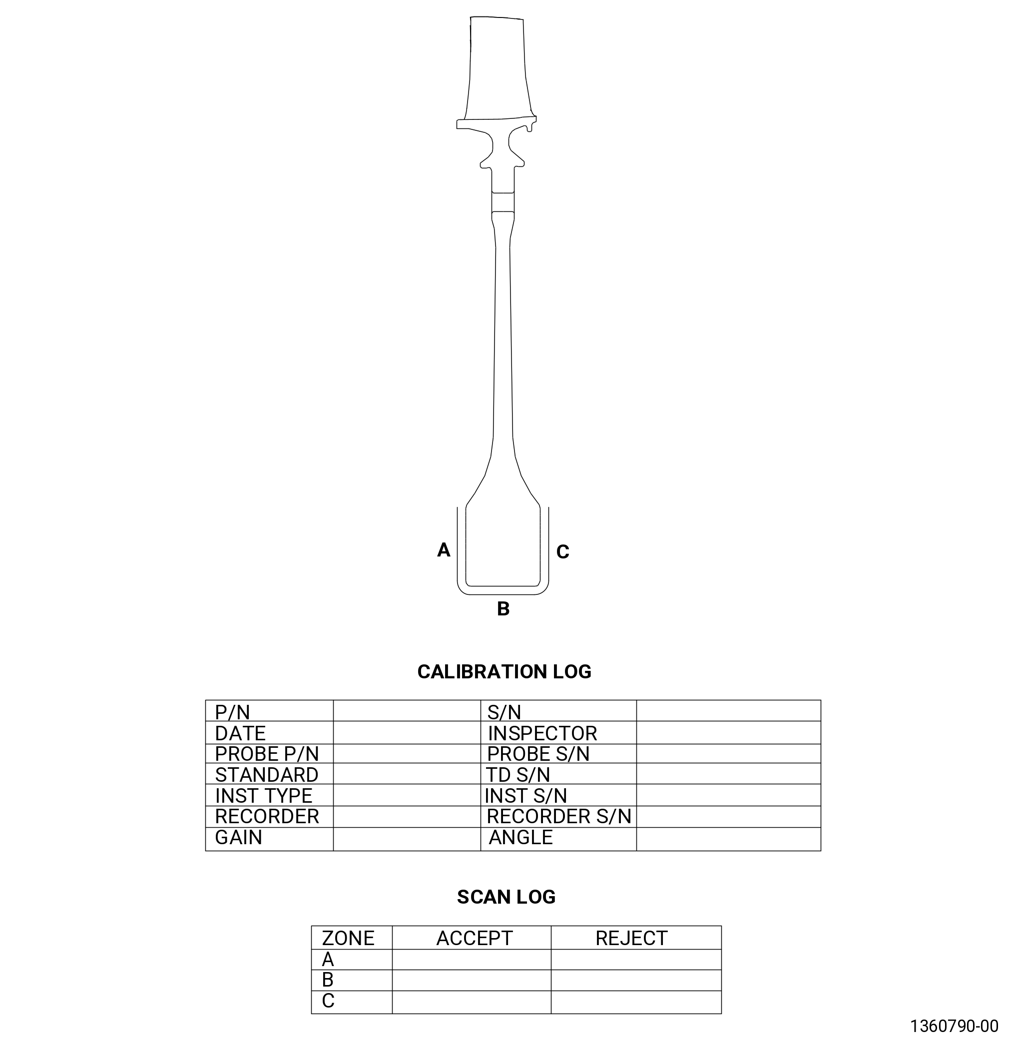
| C. | Do an eddy current inspection of the blisk bore as follows. Refer to Figure 802. |
| (1) | Clean the blisk. Refer to TASK 72-31-44-100-801 (72-31-44, CLEANING 001). |
| Subtask 72-31-44-250-004 |
| (2) | Do an eddy current inspection of the bore surfaces. Refer to TASK 70-32-10-250-003 (2 MHZ EDDY CURRENT INSPECTION OF BORES IN ROTATING ENGINE HARDWARE USING SYSTEMS UNDER COMPUTER, NUMERIC, OR ROBOTIC CONTROL). |
| NOTE: |
|
| (b) | Inspect the bore areas shown in the scan plan. |
| NOTE: |
|
| (c) | Complete the eddy current data sheets. |
| (d) | Eddy current inspection evaluation limits. |
| 1 | The evaluation limit is 1500 mV. |
| (e) | Eddy current inspection reject limits. |
| 1 | The reject limit is 1500 mV after evaluation is complete. |
| (f) | All stage 5 HPC blisks that are rejected are not serviceable. All blisks that are not rejected are serviceable. |
| Subtask 72-31-44-250-005 |
| (g) | Make sure that all records that were made during the eddy current inspection are complete. Permanently keep these records for each stage 5 HPC blisk that was inspected. |
| Subtask 72-31-44-250-003 |
| * * * SB 72-0157 |
| * * * SB 72-0020( Introduction of New Stage 5 Blisk ) |
| D. | Do an eddy current inspection of the blisk boltholes as follows: |
| CAUTION: |
|
| (1) | Clean the blisk. Refer to TASK 72-31-44-100-801 (72-31-44, CLEANING 001). |
| NOTE: |
|
| (2) | If necessary, mechanically clean the bolthole surfaces. Refer to TASK 70-22-06-110-043 (SPECIAL CLEANING PROCEDURE 6 - BOLTHOLE CLEANING FOR EDDY CURRENT INSPECTION). |
| Subtask 72-31-44-250-006 |
| (3) | Do an eddy current inspection of the boltholes. Refer to TASK 70-32-07-250-001 (HIGH SPEED AND SLOW SPEED EDDY CURRENT INSPECTION OF CIRCULAR HOLES IN INCONEL OR TITANIUM ENGINE PARTS). |
| NOTE: |
|
| (a) | Do an eddy current inspection of the boltholes as follows: |
| 1 | Use the GE-FQAP-652 inspection kit with either the GE-FQAP- 302 inspection kit, GE-FQAP-302A inspection kit, GE-FQAP-302B inspection kit, or GE- FQAP-302C inspection kit. |
| 2 | Use the following filter settings for the equipment used to do the eddy current inspection: |
|
| (b) | Eddy current inspection evaluation limits. |
| 1 | For high speed eddy current inspection, the evaluation limit is four major divisions. |
| (c) | Eddy current inspection reject limits. |
| 1 | For high speed eddy current inspection, the rejection limit is four major divisions after the evaluation is complete. |
| (d) | All stage 5 blisks that are rejected are not serviceable. |
| Subtask 72-31-44-250-007 |
| (e) | Make sure that all records that were made during the eddy current inspection are complete. Permanently keep these records for each stage 5 blisk that was inspected. |
| NOTE: |
|
| * * * END SB 72-0020 |
| * * * END SB 72-0157 |
| 5 . | Visual Inspection. |
| Refer to Figure 803. |
| Subtask 72-31-44-220-043 |
| A. | Do an inspection of all areas for: |
| (1) | Cracks: |
| Maximum serviceable limit: |
|
| Repair method: |
|
| Subtask 72-31-44-220-007 |
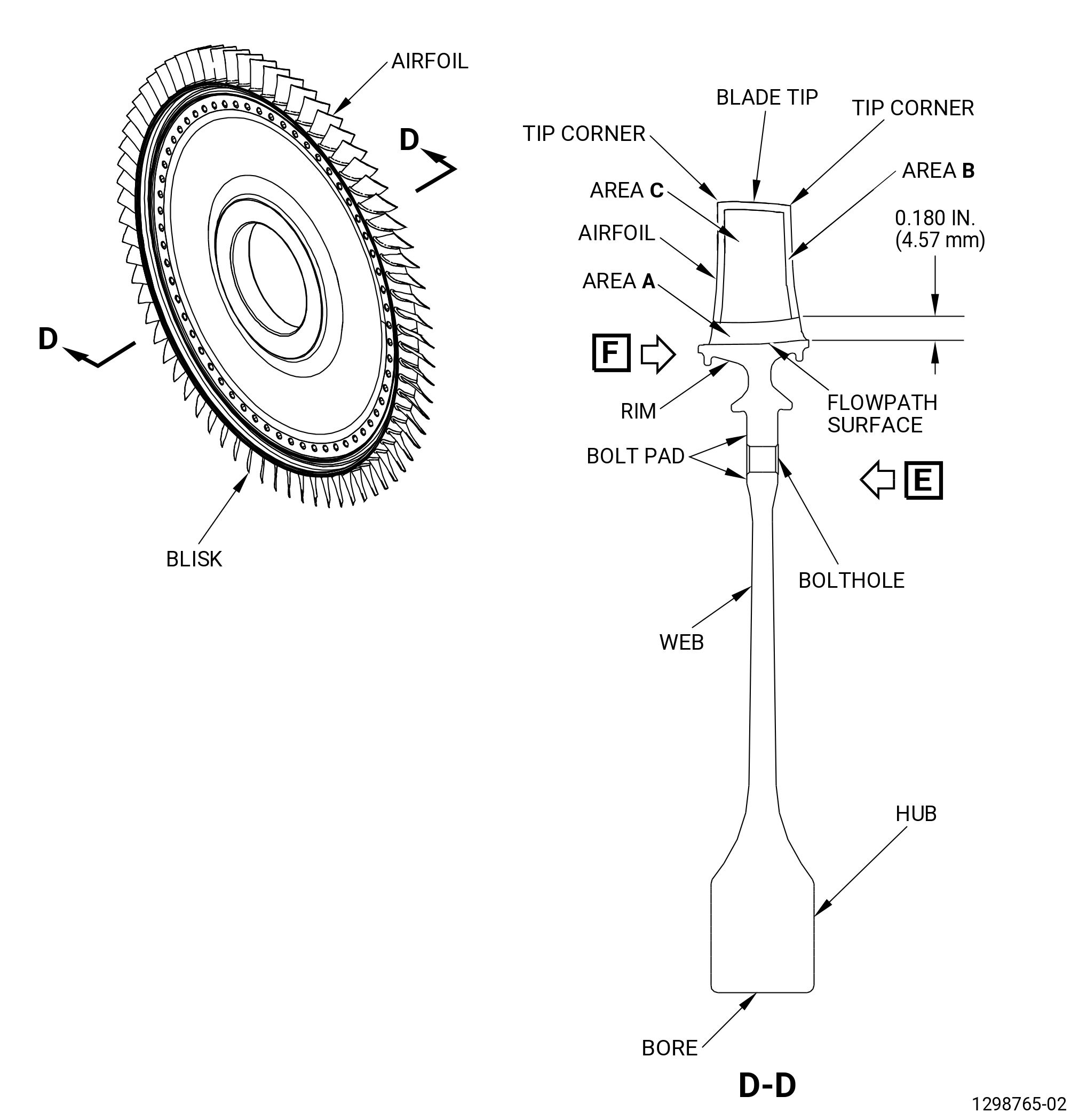
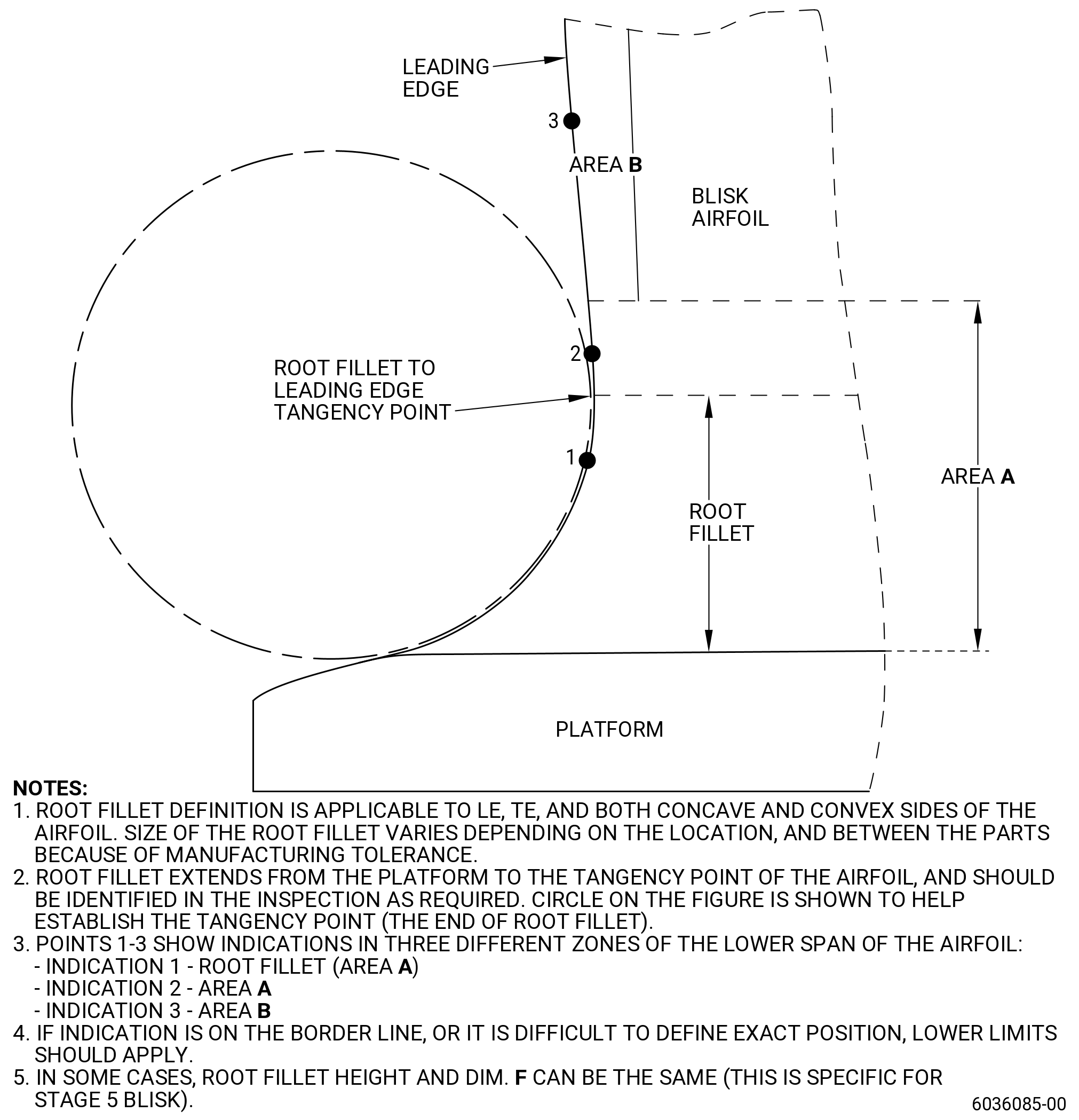
| B. | Do an inspection of area A (critical) of the blisk airfoils for. Refer to Figure 805. |
| * * * PRE SB 72-0492 |
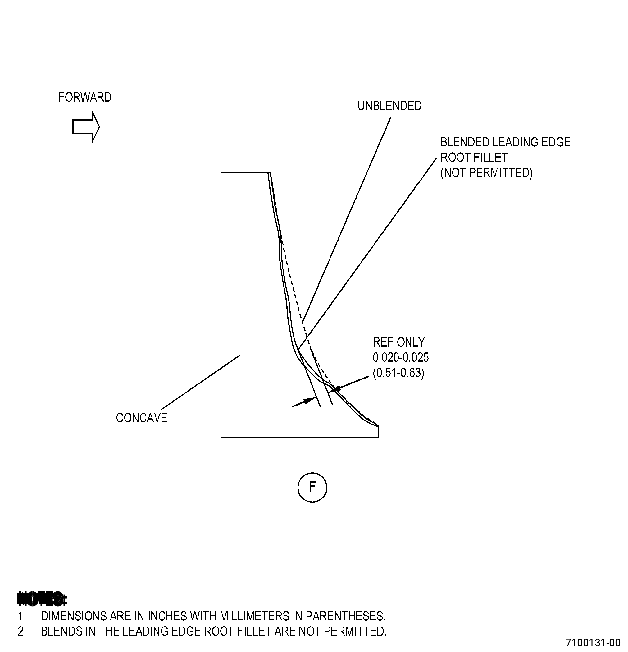
| (1) | Blended fillet in the leading edge area. Refer to Figure 804 and do as follows: |
| NOTE: |
|
| NOTE: |
|
| Maximum serviceable limit: |
|
| Repair method: |
|
| * * * END PRE SB 72-0492 |
| Subtask 72-31-44-220-070 |
| * * * SB 72-0492 |
| (2) | Blended fillet in the leading edge area. Refer to Figure 804 and do as follows: |
| NOTE: |
|
| Maximum serviceable limit: |
|
| Repair method: |
|
| * * * END SB 72-0492 |
| Subtask 72-31-44-220-069 |
| (3) | Nicks and pits in the fillet (except leading edge): |
| Maximum serviceable limit: |
|
| Repair method: |
|
| Subtask 72-31-44-220-071 |
| * * * PRE SB 72-0492 |
| (4) | Nicks and pits in the leading edge of the fillet: |
| NOTE: |
|
| Maximum serviceable limit: |
|
| Repair method: |
|
| * * * END PRE SB 72-0492 |
| Subtask 72-31-44-220-072 |
| * * * SB 72-0492 |
| (5) | Nicks and pits in the leading edge of the fillet: |
| Maximum serviceable limit: |
|
| Repair method: |
|
| * * * END SB 72-0492 |
| Subtask 72-31-44-220-073 |
| * * * PRE SB 72-0492 |
| (6) | Dents in the leading edge of the fillet: |
| NOTE: |
|
| Maximum serviceable limit: |
|
| Repair method: |
|
| * * * END PRE SB 72-0492 |
| Subtask 72-31-44-220-074 |
| * * * SB 72-0492 |
| (7) | Dents in the leading edge of the fillet: |
| Maximum serviceable limit: |
|
| Repair method: |
|
| * * * END SB 72-0492 |
| Subtask 72-31-44-220-044 |
| (8) | Dent in the fillet (except the leading edge of the fillet): |
| Maximum serviceable limit: |
|
| Repair method: |
|
| Subtask 72-31-44-220-045 |
| (9) | Scratches in the fillet (except the leading edge): |
| Maximum serviceable limit: |
|
| Repair method: |
|
| Subtask 72-31-44-220-078 |
| * * * PRE SB 72-0492 |
| (10) | Scratches in the leading edge of the fillet: |
| NOTE: |
|
| Maximum serviceable limit: |
|
| Repair method: |
|
| * * * END PRE SB 72-0492 |
| Subtask 72-31-44-220-075 |
| * * * SB 72-0492 |
| (11) | Scratches in the leading edge of the fillet: |
| Maximum serviceable limit: |
|
| Repair method: |
|
| * * * END SB 72-0492 |
| Subtask 72-31-44-220-046 |
| (12) | Tears and cracks in the leading edge of the fillet: |
| NOTE: |
|
| Maximum serviceable limit: |
|
| Repair method: |
|
| Subtask 72-31-44-220-076 |
| (13) | Tears and cracks in the fillet except the leading edge of the fillet: |
| Maximum serviceable limit: |
|
| Repair method: |
|
| Subtask 72-31-44-220-047 |
| (14) | Nicks, dents, and pits on the leading and trailing edges: |
| Maximum serviceable limit: |
|
| Repair method: |
|
| Subtask 72-31-44-220-048 |
| (15) | Tears and cracks on the leading and trailing edges: |
| Maximum serviceable limit: |
|
| Repair method: |
|
| Subtask 72-31-44-220-049 |
| (16) | Deposits on the leading and trailing edges: |
| Maximum serviceable limit: |
|
| Repair method: |
|
| Subtask 72-31-44-220-050 |
| (17) | Scratches and gouges on the leading and trailing edges: |
| Maximum serviceable limit: |
|
| Repair method: |
|
| Subtask 72-31-44-220-051 |
| (18) | Bulge deformation on the leading and trailing edges: |
| Maximum serviceable limit: |
|
| Repair method: |
|
| Subtask 72-31-44-220-009 |
| C. | Do an inspection of area B (leading and trailing edges) on the blisk airfoils for: |
| (1) | Nicks: |
| Maximum serviceable limit: |
|
| Repair method: |
|
| Subtask 72-31-44-220-010 |
| NOTE: |
|
| (2) | Dents and pits: |
| Maximum serviceable limit: |
|
| Repair method: |
|
| Subtask 72-31-44-220-011 |
| (3) | Scratches and gouges: |
| Maximum serviceable limit: |
|
| Repair method: |
|
| Subtask 72-31-44-220-012 |
| (4) | Deposits: |
| Maximum serviceable limit: |
|
| Repair method: |
|
| Subtask 72-31-44-220-013 |
| (5) | Metal splatter deposits: |
| Maximum serviceable limit: |
|
| Repair method: |
|
| Subtask 72-31-44-220-014 |
| (6) | Erosion on the leading edge: |
| Maximum serviceable limit: |
|
| Repair method: |
|
| Subtask 72-31-44-220-015 |
| (7) | Cracks: |
| Maximum serviceable limit: |
|
| Repair method: |
|
| Subtask 72-31-44-220-016 |
| (8) | Bulge deformation: |
| Maximum serviceable limit: |
|
| Repair method: |
|
| Subtask 72-31-44-220-055 |
| (9) | Tears: |
| Maximum serviceable limit: |
|
| Repair method: |
|
| Subtask 72-31-44-220-017 |
| D. | Do an inspection of area C (concave and convex airfoil contour surfaces) of the blisk blade for: |
| (1) | Nicks, dents, and pits: |
| Maximum serviceable limit: |
|
| Repair method: |
|
| Subtask 72-31-44-220-018 |
| (2) | Scratches: |
| Maximum serviceable limit: |
|
| Repair method: |
|
| Subtask 72-31-44-220-019 |
| (3) | Metal splatter deposits: |
| Maximum serviceable limit: |
|
| Repair method: |
|
| Subtask 72-31-44-220-020 |
| E. | Do an inspection of the airfoil for: |
| (1) | Bent airfoil: |
| Maximum serviceable limit: |
|
| Repair method: |
|
| Subtask 72-31-44-220-021 |
| F. | Do an inspection of the flowpath surface of the blisk for: |
| (1) | Nicks, dents, pits, and scratches: |
| Maximum serviceable limit: |
|
| Repair method: |
|
| Subtask 72-31-44-220-022 |
| G. | Do an inspection of the blade tip of the blisk for. Refer to Figure 806 and Figure 807. |
| (1) | Nicks, dents, and cracks: |
| Maximum serviceable limit: |
|
| Repair method: |
|
| Subtask 72-31-44-220-023 |
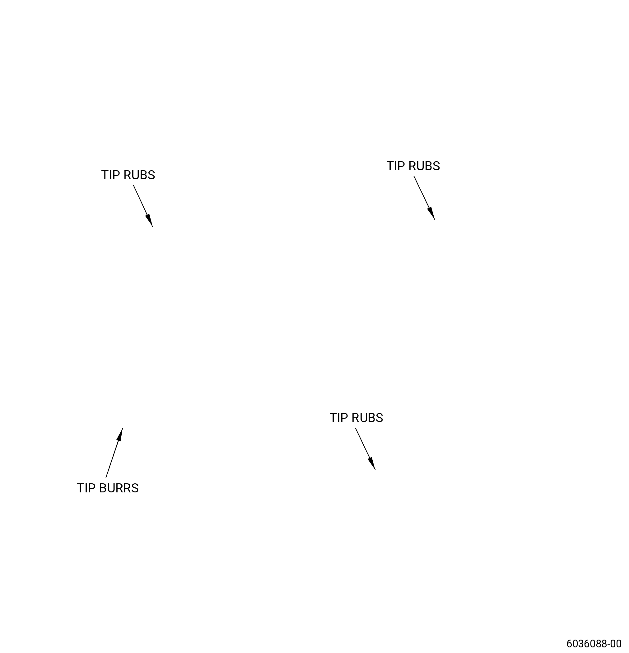
| (2) | Tip rub: |
| NOTE: |
|
| Maximum serviceable limit: |
|
| Repair method: |
|
| Subtask 72-31-44-220-024 |
| (3) | Burrs and high metal: |
| NOTE: |
|
| Maximum serviceable limit: |
|
| Maximum repairable limit: |
|
| Repair method: |
|
| Subtask 72-31-44-220-025 |
| * * * PRE SB 72-0492 |
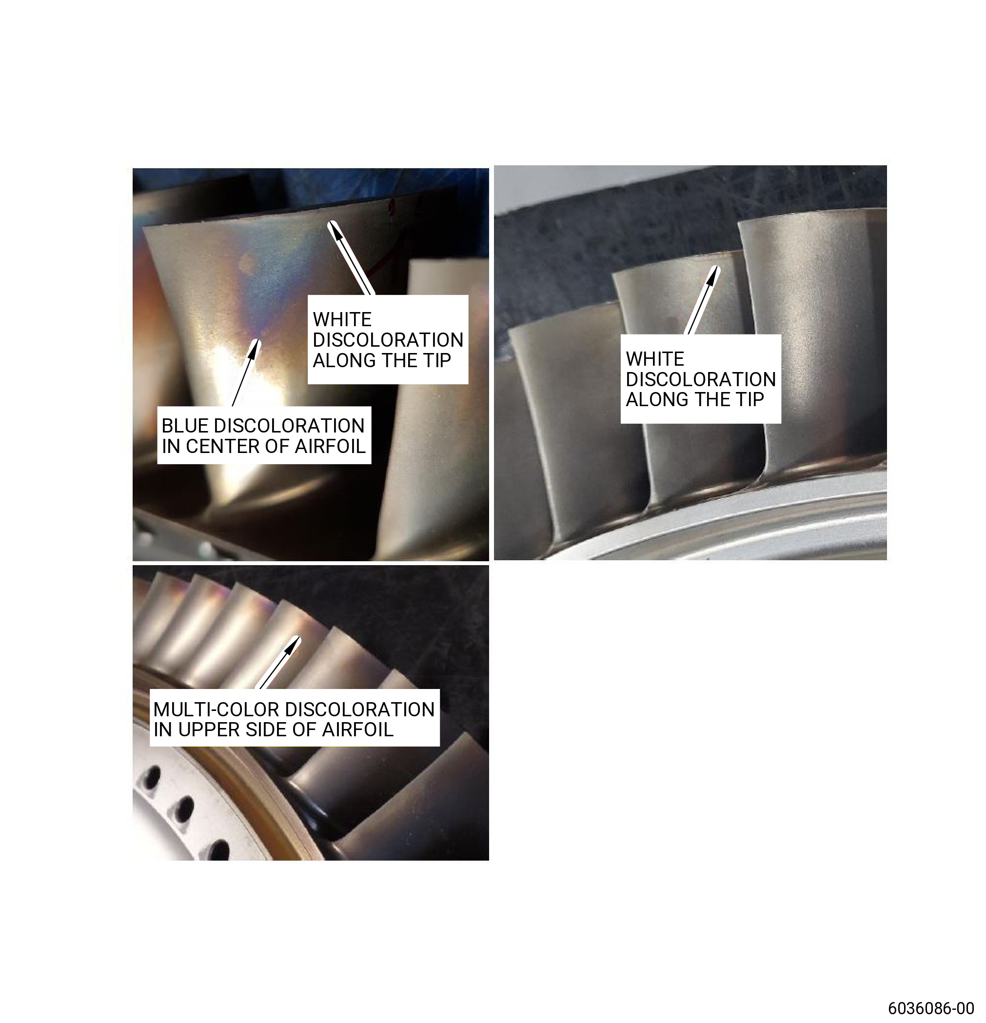
| (4) | Heat discoloration caused by tip rub: |
| NOTE: |
|
| NOTE: |
|
| NOTE: |
|
| NOTE: |
|
| NOTE: |
|
| Maximum serviceable limit: |
|
| Repair method: |
|
| * * * END PRE SB 72-0492 |
| Subtask 72-31-44-220-077 |
| * * * SB 72-0492 |
| (5) | Heat discoloration caused by tip rub: |
| Maximum serviceable limit: |
|
| Repair method: |
|
| * * * END SB 72-0492 |
| Subtask 72-31-44-220-026 |
| (6) | Deposits: |
| Maximum serviceable limit: |
|
| Repair method: |
|
| Subtask 72-31-44-220-027 |
| (7) | Bending and curling of the squealer tip: |
| Maximum serviceable limit: |
|
| Repair method: |
|
| Subtask 72-31-44-220-028 |
| (8) | Erosion: |
| Maximum serviceable limit: |
|
| Repair method: |
|
| Subtask 72-31-44-220-030 |
| H. | Do an inspection of the tip corners of the blisk airfoils for: |
| (1) | Damage: |
| Maximum serviceable limit: |
|
| Repair method: |
|
| Subtask 72-31-44-220-031 |
| I. | Do an inspection of all disk surfaces (does not include the airfoils) for: |
| (1) | Nicks and scratches: |
| Maximum serviceable limit: |
|
| Repair method: |
|
| Subtask 72-31-44-220-032 |
| (2) | Dents: |
| Maximum serviceable limit: |
|
| Repair method: |
|
| Subtask 72-31-44-220-033 |
| J. | Do an inspection of the boltholes for: |
| (1) | Nicks, dents, pits, and scratches on the inner diameter: |
| Maximum serviceable limit: |
|
| Repair method: |
|
| Subtask 72-31-44-220-036 |
| K. | Do an inspection of the bolt pad faces for: |
| (1) | Fretting and galling: |
| Maximum serviceable limit: |
|
| Repair method: |
|
| Subtask 72-31-44-220-067 |
| L. | Do an inspection of the forward rabbet and aft rabbet (diameter Y and diameter AZ) for: |
| NOTE: |
|
| (1) | Fretting and galling on parent metal: |
| Maximum serviceable limit: |
|
| Repair method: |
|
| Subtask 72-31-44-220-068 |
| (2) | Chipped or missing coating: |
| Maximum serviceable limit: |
|
| Repair method: |
|
| 6 . | Special Dimensional Inspection. |
| Subtask 72-31-44-220-059 |
| A. | Deleted. |
| Subtask 72-31-44-220-063 |
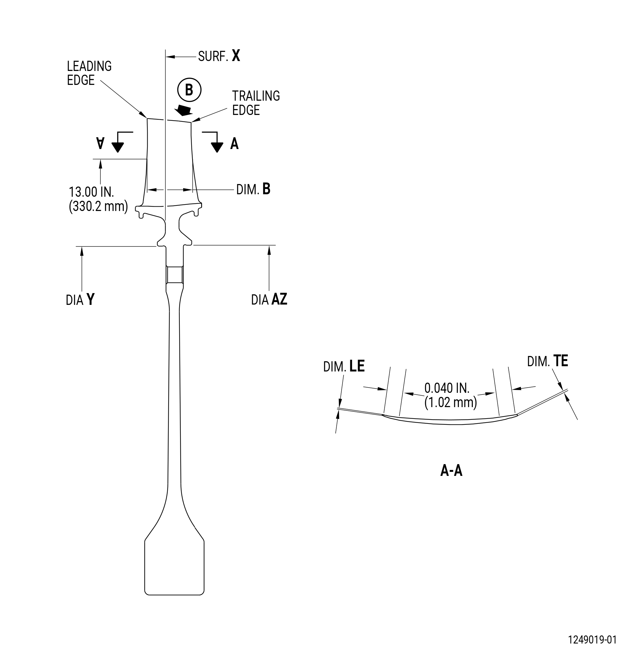
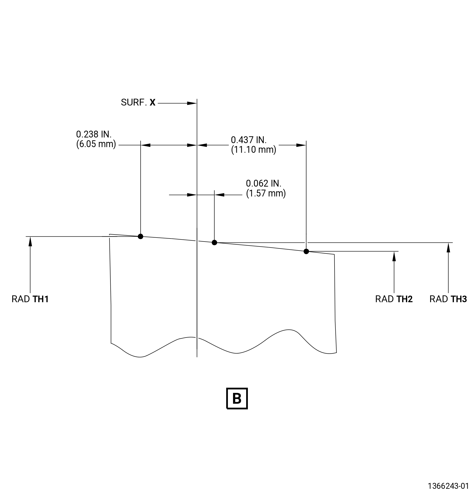
| B. | Measure all dimensions with surface X held flat to 0.003 inch (0.08 mm) and diameter Y held within 21.031-21.026 inches (534.19-534.06 mm). |
| Subtask 72-31-44-220-037 |
| C. | Measure the dimensions that follow: |
| (1) | Dimension B: |
| NOTE: |
|
| Minimum serviceable limit: |
|
| Repair method: |
|
| Subtask 72-31-44-220-038 |
| (2) | Dimension LE: |
| NOTE: |
|
| Minimum serviceable limit: |
|
| Repair method: |
|
| Subtask 72-31-44-220-039 |
| (3) | Dimension TE: |
| NOTE: |
|
| Minimum serviceable limit: |
|
| Repair method: |
|
| Subtask 72-31-44-220-041 |
| (4) | Diameter Y: |
| Maximum serviceable limit: |
|
| Repair method: |
|
| Subtask 72-31-44-220-042 |
| (5) | Diameter AZ: |
| Maximum serviceable limit: |
|
| Repair method: |
|
| Subtask 72-31-44-220-060 |
| D. | Do an inspection of the height of the airfoil for: |
| NOTE: |
|
| (1) | Radius TH1: |
| Minimum serviceable limit: |
|
| Repair method: |
|
| Subtask 72-31-44-220-061 |
| (2) | Radius TH2: |
| Minimum serviceable limit: |
|
| Repair method: |
|
| Subtask 72-31-44-220-062 |
| (3) | Radius TH3: |
| Minimum serviceable limit: |
|
| Repair method: |
|