| GENX-1B CLEANING,INSPECTION,AND REPAIR MANUAL | Dated: 08/04/2020 | |
| CIR 72-31-46 , REPAIR 004 | ||
| COMPRESSOR DISCHARGE PRESSURE ROTATING SEAL - REPAIR - SEAL TEETH BLEND REPAIR | ||
| GENX-1B CLEANING,INSPECTION,AND REPAIR MANUAL | Dated: 08/04/2020 | |
| CIR 72-31-46 , REPAIR 004 | ||
| COMPRESSOR DISCHARGE PRESSURE ROTATING SEAL - REPAIR - SEAL TEETH BLEND REPAIR | ||
| * * * FOR ALL |
| TASK 72-31-46-300-804 |
| 1 . | Seal Teeth Blend Repair. |
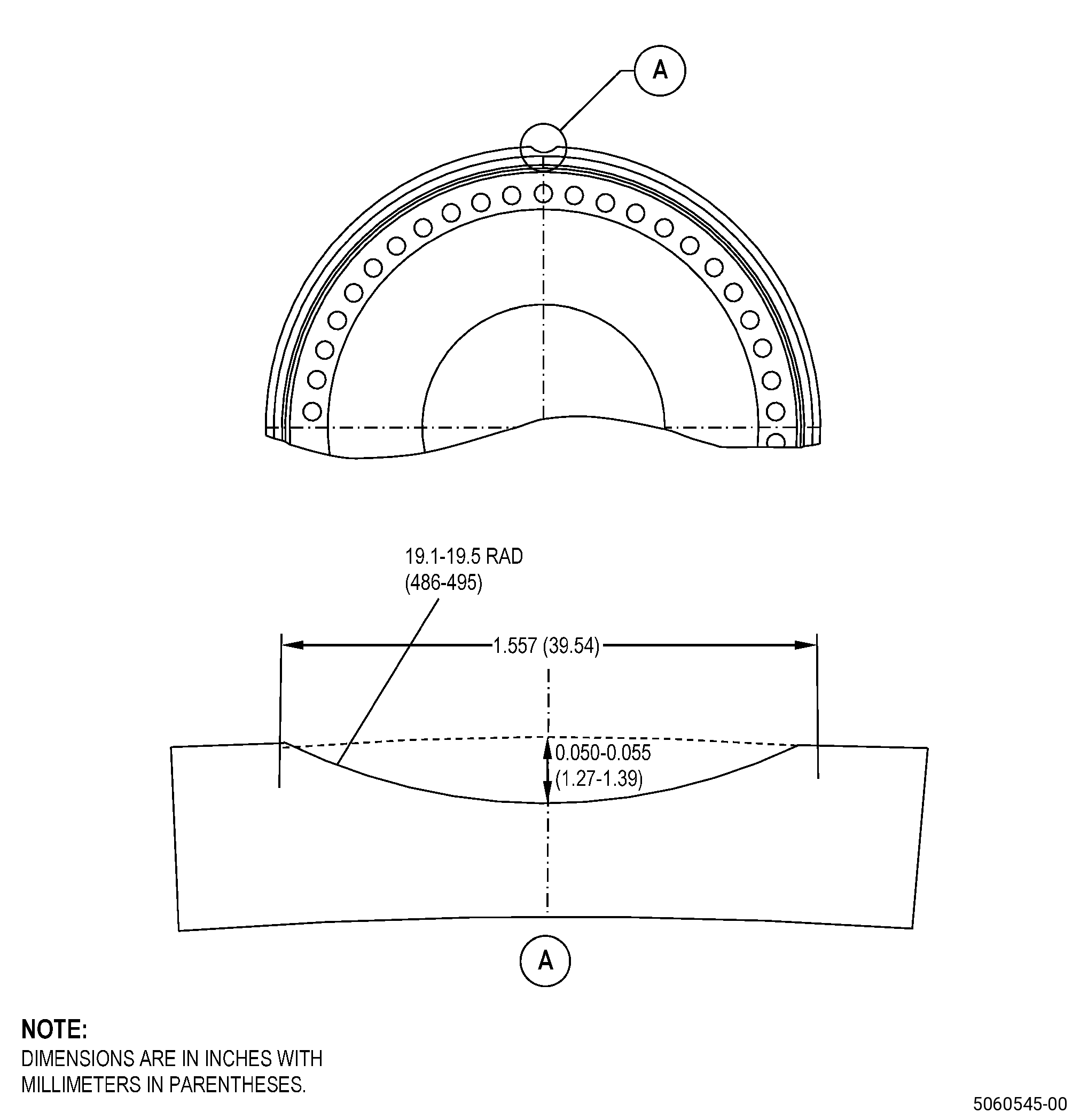
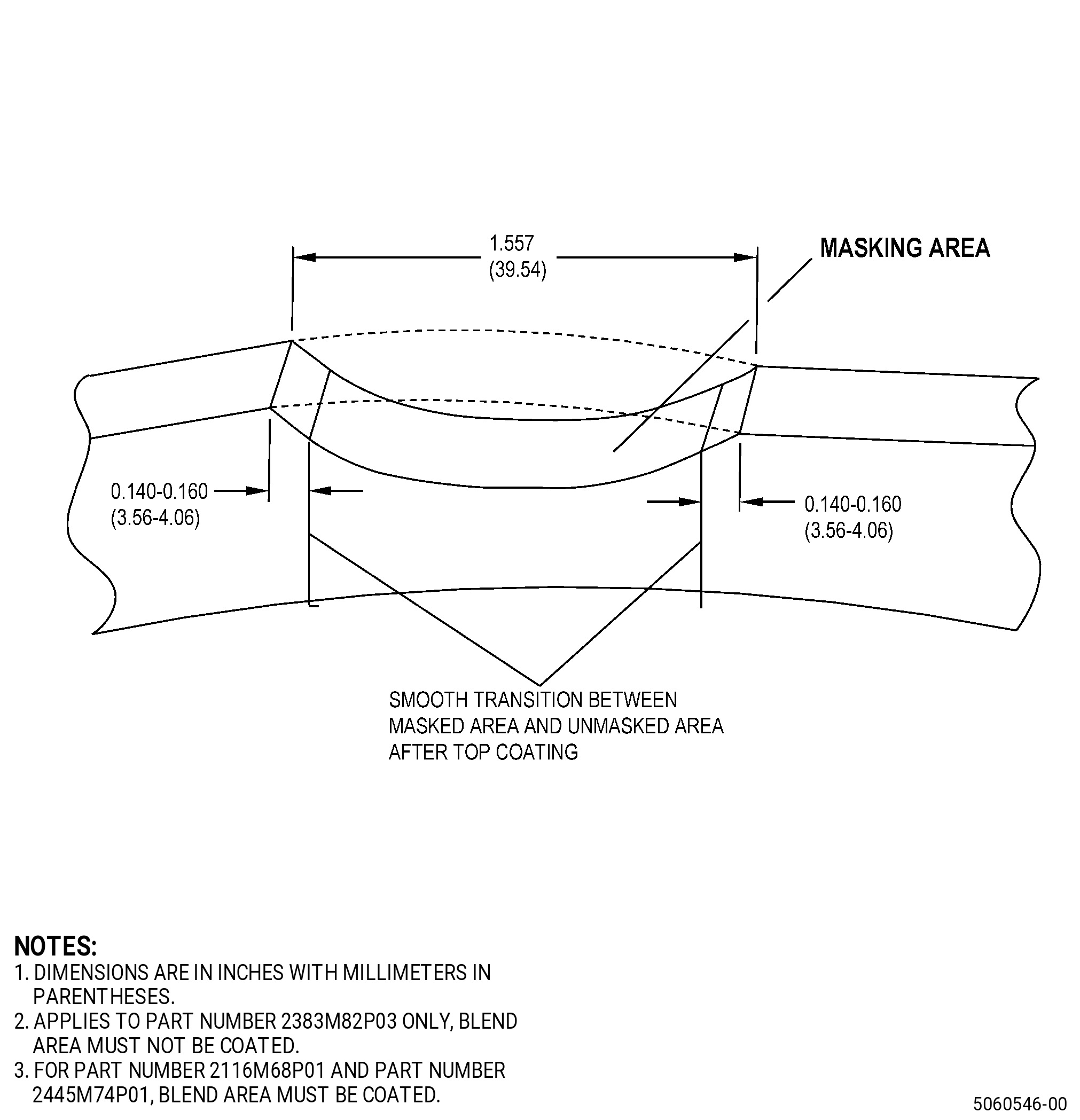
| A. | This procedure gives instructions to repair the compressor discharge pressure (CDP) rotating seal (seal) by blending to remove damage and repair the thermal spray coating on the seal teeth. Refer to Figure 901. |
| NOTE: |
|
| B. | The following maximum repairable limits apply to this repair: |
| NOTE: |
|
| (4) | Visual Inspection. |
| (i) | Do an inspection of the seal serrations for: |
| 1 | Nicks, tears, dents, or bends: |
| Maximum repairable limit: |
|
| C. | The subsequent table gives a list of the part numbers that are applicable to this repair. All part numbers are applicable to all paragraphs unless specified differently. |
|
|||||||||||||||||||||||
| D. | Proprietary/Complex Process Statement. |
| (1) | None. |
| 2 . | Tools, Equipment, and Materials. |
| NOTE: |
|
| A. | Tools and Equipment. |
| (1) | Special Tools. None. |
| (2) | Standard Tools and Equipment. None. |
| (3) | Locally Manufactured Tools. |
|
| B. | Consumable Materials. |
|
| C. | Referenced Procedures. |
| D. | Expendable Parts. None. |
| E. | SPD Information. |
| (1) | Locally Manufactured SPD. None. |
| F. | Special Solutions. None. |
| G. | Test Specimens. TASK 70-49-35-340-037 (THERMAL BARRIER COATING SYSTEM - YTTRIUM OXIDE STABILIZED ZIRCONIUM OXIDE (8% YTTRIUM OXIDE) OVER NICKEL CHROMIUM ALUMINUM YTTRIUM BONDCOAT) and TASK 70-49-02-340-003 (THERMAL SPRAYING ALUMINUM OXIDE - ALUMINA (POWDER)). |
| 3 . | Dimensional Information. |
| Subtask 72-31-46-220-044 |
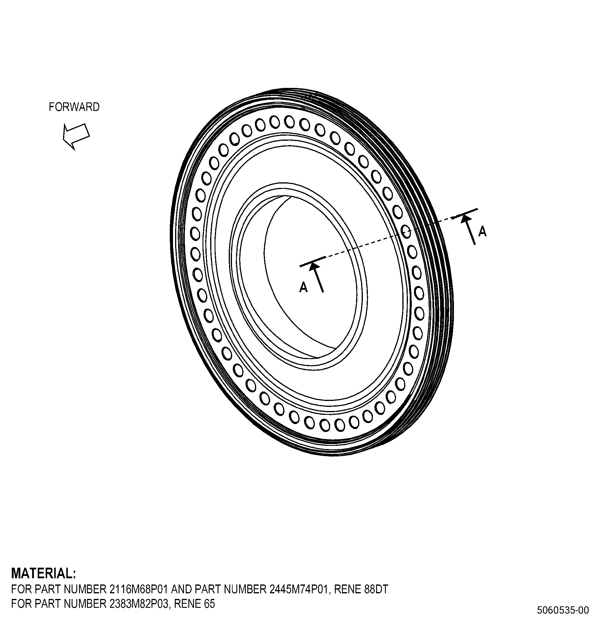
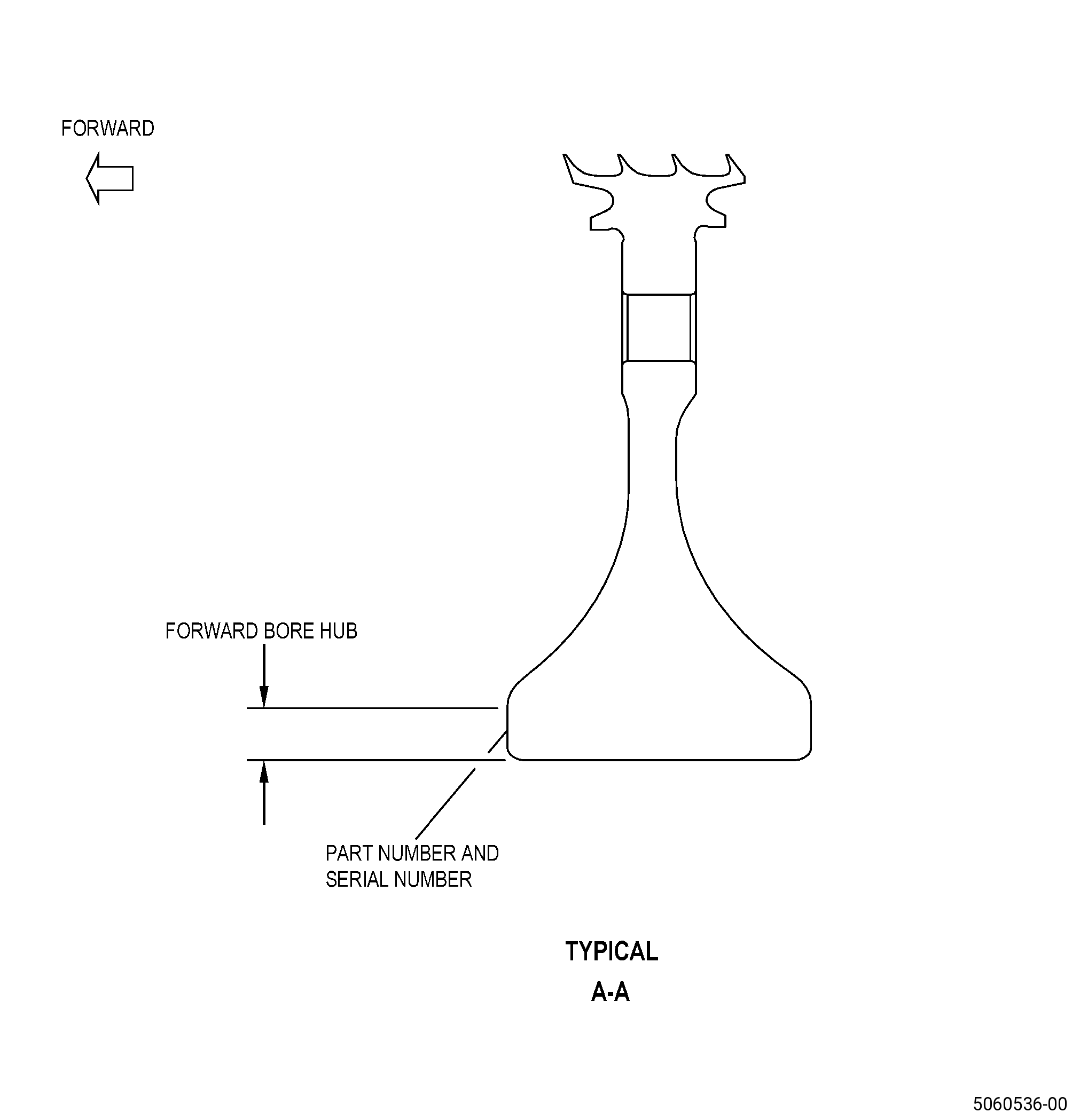
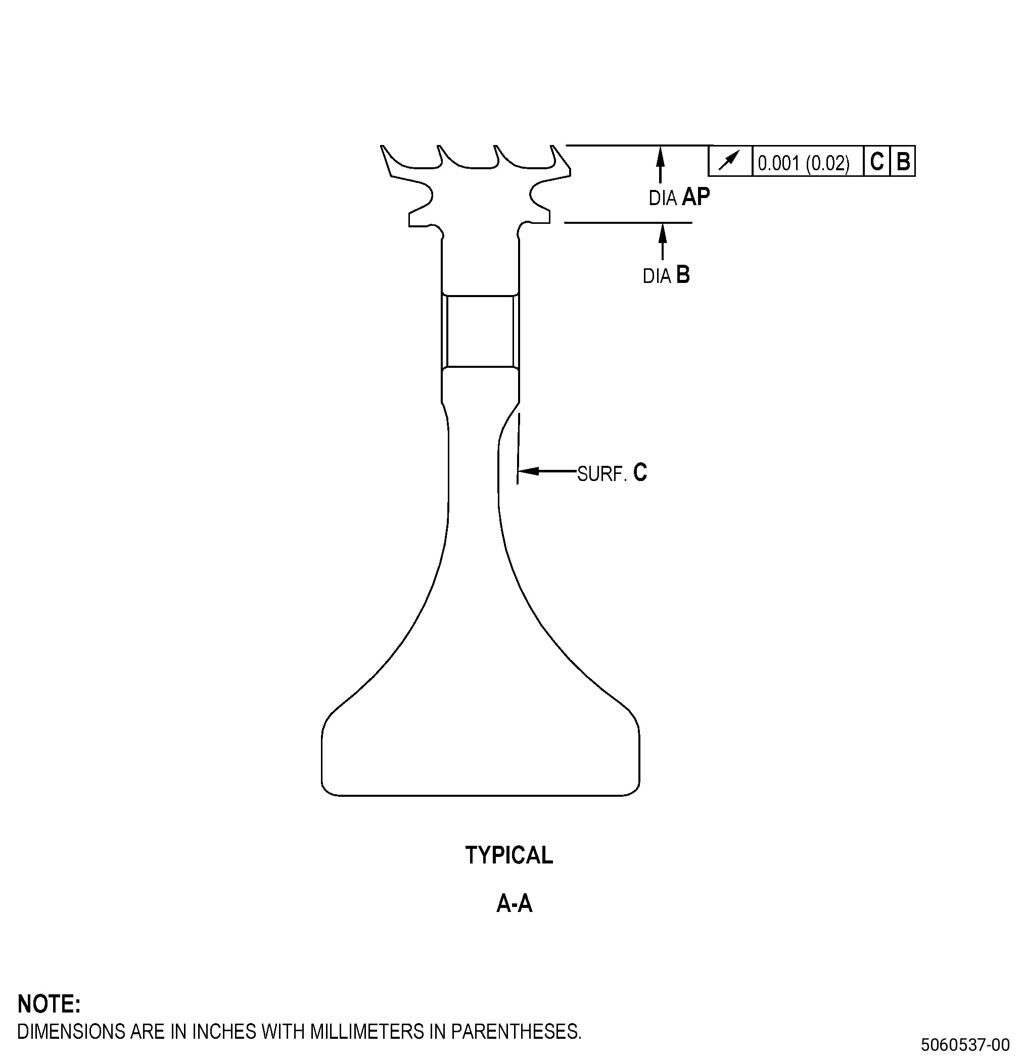
| A. | Refer to Figure 901 for specified dimensions and locations. |
| NOTE: |
|
| NOTE: |
|
|
| 4 . | Setup Information. |
| Subtask 72-31-46-350-012 |
| A. | Set-up the seal for removing thermal spray coating/shotpeening/grit blasting as follows: |
| Subtask 72-31-46-930-003 |
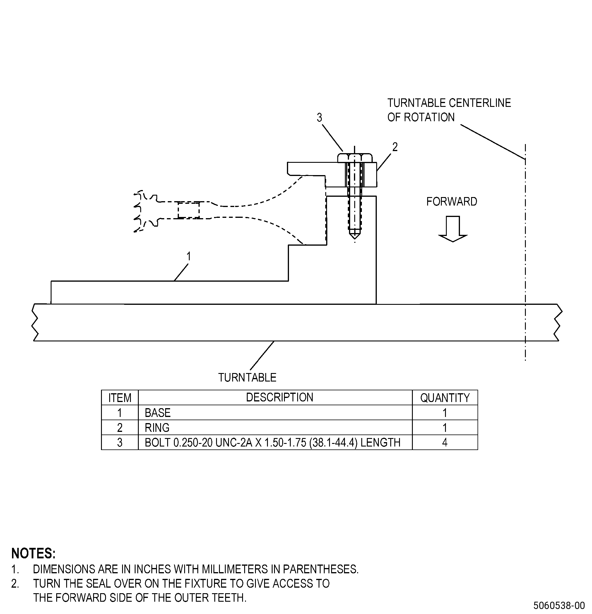
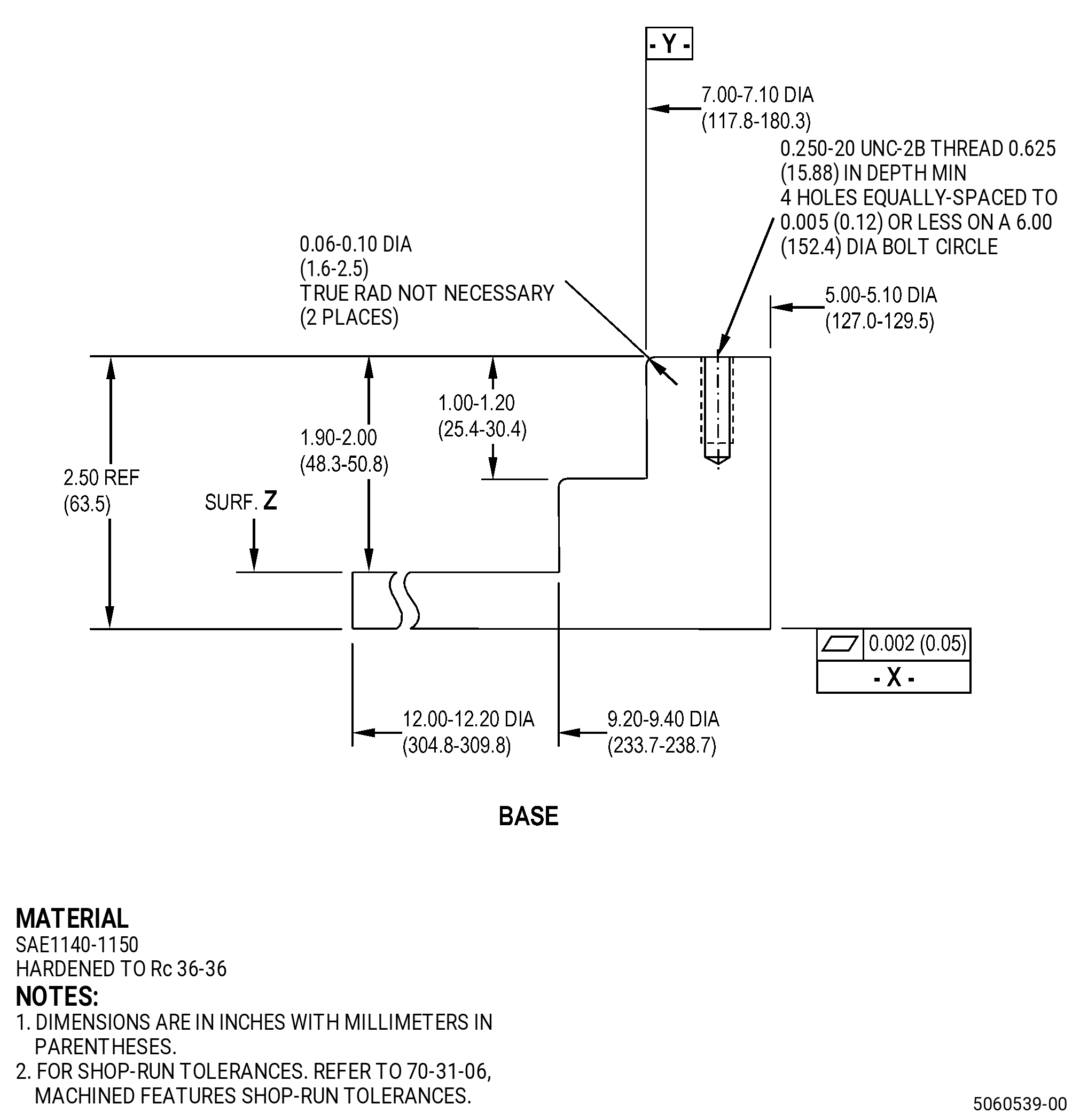
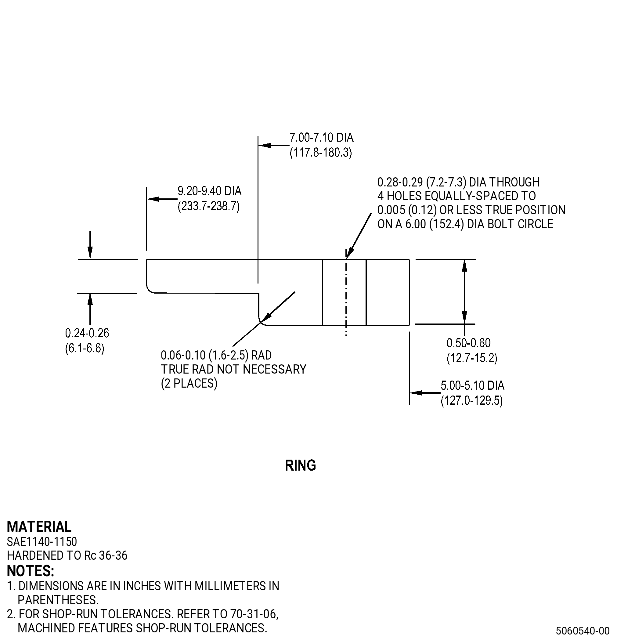
| (1) | If necessary, make the holding fixture. Refer to Figure 902. |
| Subtask 72-31-46-350-018 |
| (2) | Put the holding fixture on the rotating table. |
| (3) | Install the seal in the holding fixture. |
| Subtask 72-31-46-220-047 |
| (4) | Diameter Y must be concentric with the axis of rotation to 0.050 inch (1.27 mm) or less. |
| (5) | Surface Z must have a runout of 0.050 inch (1.27 mm) or less. |
| Subtask 72-31-46-350-019 |
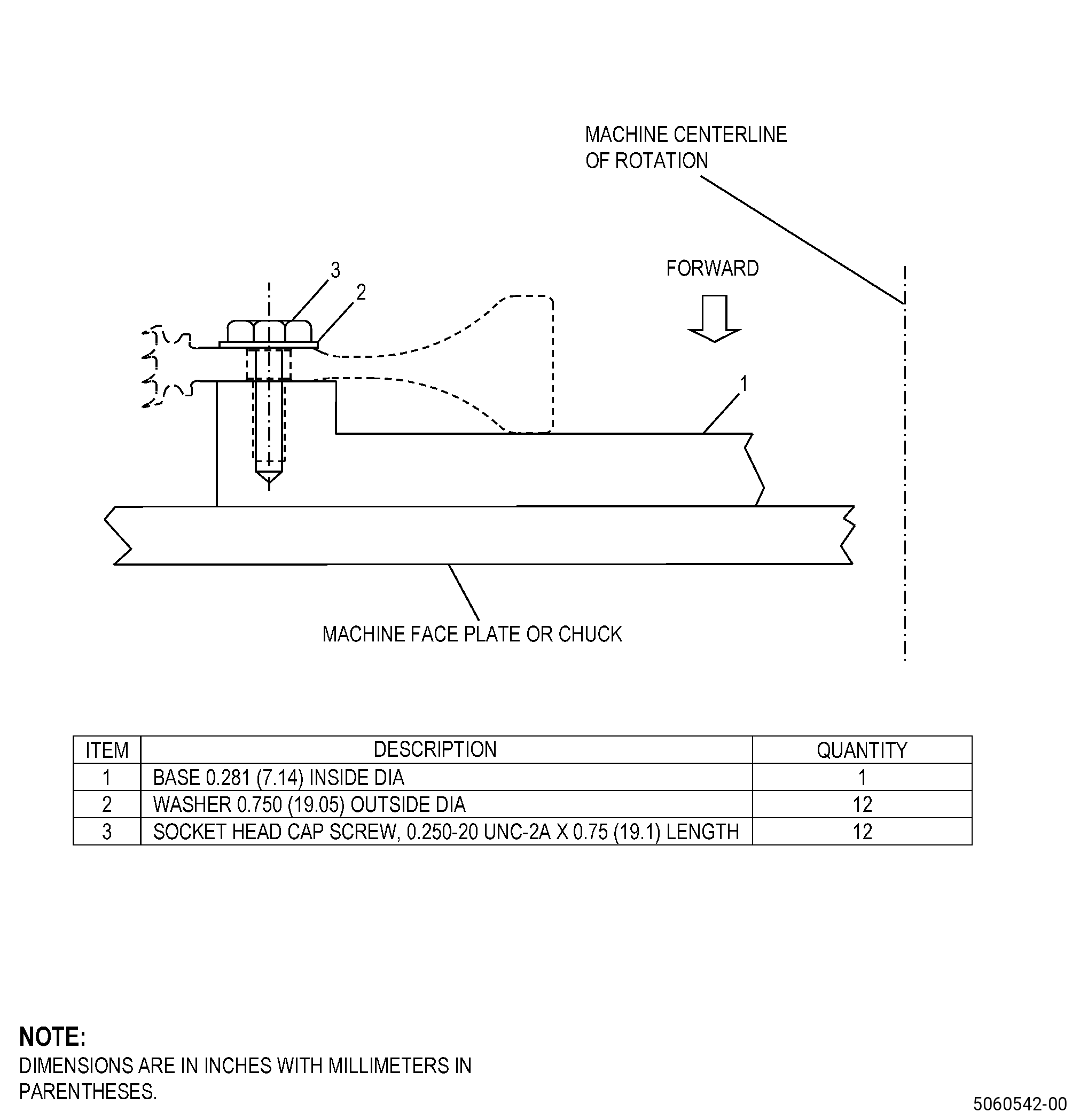
| (6) | Put the seal on the holding fixture, aft side up, and put the holding fixture ring on the seal. |
| Subtask 72-31-46-220-048 |
| (7) | Diameter AP must have a runout of 0.050 inch (1.27 mm) or less. |
| (8) | Surface C must have a runout of 0.050 inch (1.27 mm) or less. |
| Subtask 72-31-46-350-020 |
| (9) | Tighten the bolts. Refer to TASK 70-51-00-400-004 (TIGHTENING PRACTICES AND TORQUE VALUES). |
| Subtask 72-31-46-350-013 |
| B. | Set-up the seal for machining as follows: |
| Subtask 72-31-46-930-004 |
| (1) | If necessary, make the machining fixture. Refer to Figure 903. |
| Subtask 72-31-46-350-021 |
| (2) | Put the machining fixture on the machining table. |
| Subtask 72-31-46-220-049 |
| (3) | Diameter FB must be concentric with the axis of rotation to 0.001 inch (0.02 mm) or less. |
| (4) | The runout of surface FA must be 0.001 inch (0.02 mm) or less. |
| Subtask 72-31-46-350-022 |
| (5) | Put the seal on the machining fixture as follows: |
| (a) | Put the seal in the machining fixture base with the aft side up. |
| (b) | Install 12 washers and 12 bolts equally-spaced through the seal and into the machining fixture. |
| Subtask 72-31-46-220-050 |
| (c) | Diameter B must have a runout of 0.001 inch (0.02 mm) or less. |
| (d) | Surface C must have a runout of 0.001 inch (0.02 mm) or less. |
| Subtask 72-31-46-350-023 |
| (e) | Tighten the bolts. Refer to TASK 70-51-00-400-004 (TIGHTENING PRACTICES AND TORQUE VALUES). |
| 5 . | Procedure. |
| NOTE: |
|
| Subtask 72-31-46-160-004 |
| A. | If necessary, clean the seal. Refer to TASK 72-31-46-100-001 (72-31-46, CLEANING 001). |
| Subtask 72-31-46-330-001 |
| B. | Remove thermal spray coating from the seal teeth as follows: |
| Subtask 72-31-46-350-014 |
| (1) | Set-up the seal in the holding fixture. Refer to Subtask 72-31-46-350-012 (paragraph 4.A.) and Figure 902. |
| Subtask 72-31-46-330-002 |
| (2) | Remove the thermal spray coating from the seal teeth as follows: |
|
|
||||||||||||||||||||||||||||||||||||||||||||||||||||||||||||||||||||||||||||||||||||||||||||||
| Subtask 72-31-46-350-015 |
| C. | Blend the seal teeth to remove dents. Refer to TASK 70-42-00-350-002 (BLENDING AND REMOVAL OF HIGH METAL PROCEDURES), Figure 905, and as follows: |
| (1) | Remove all distorted or dented material. |
| (2) | Only one blend on the tooth that is being blended is permitted. |
| (3) | Only one blended tooth for each part is permitted. |
| Subtask 72-31-46-220-045 |
| D. | Do a dimensional inspection of the seal teeth in-process dimension. Refer to Subtask 72-31-46-220-044 (paragraph 3.A.) and as follows: |
| Subtask 72-31-46-320-005 |
| CAUTION: |
|
| (1) | If necessary, machine the seal teeth. Refer to TASK 70-00-03-800-004 (MACHINING DATA), Figure 901, and as follows: |
| Subtask 72-31-46-350-024 |
| (a) | Set-up the seal teeth for machining. Refer to Subtask 72-31-46-350-013 (paragraph 4.B.). |
| Subtask 72-31-46-320-006 |
| (b) | Machine the seal teeth to remove damage and to make the part agree with the in-process dimension. |
| Subtask 72-31-46-220-051 |
| (c) | The runout of diameter B must be 0.002 inch (0.05 mm) maximum. |
| Subtask 72-31-46-350-016 |
| E. | Blend the burrs and rolled edges from the seal teeth. Refer to TASK 70-42-00-350-002 (BLENDING AND REMOVAL OF HIGH METAL PROCEDURES) and as follows: |
| (1) | Break all sharp edges to 0.0050 inch (0.127 mm) maximum. |
| Subtask 72-31-46-160-005 |
| F. | Clean the seal teeth. Refer to TASK 70-21-00-110-051 (CHEMICAL CLEANING) and TASK 70-21-03-160-001 (CLEANING METHOD NO. 3 - STEAM CLEANING). |
| Subtask 72-31-46-110-018 |
| G. | Etch the seal teeth repair area. Refer to TASK 70-24-00-110-033 (ETCHING PROCEDURES FOR FLUORESCENT-PENETRANT INSPECTION) , TASK 70-24-01-110-034 (SWAB ETCHING PROCEDURE) , and as follows: |
| (1) | Use Class C etchant. |
| Subtask 72-31-46-230-004 |
| H. | Do an inspection of the seal teeth. Refer to TASK 70-32-00-200-002 (INDIRECT INSPECTION METHODS), TASK 70-32-03-230-002 (SPOT-FLUORESCENT-PENETRANT INSPECTION), and as follows: |
| (1) | Use Class G penetrant. |
| (2) | Indications more than 0.015 inch (0.38 mm) are not permitted. |
| Subtask 72-31-46-380-003 |
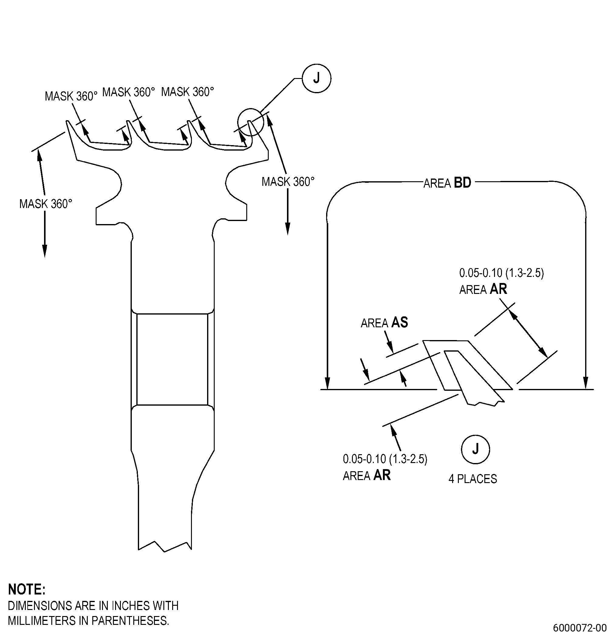
| I. | Peen area BD of the seal. Refer to TASK 70-47-01-380-016 (SHOTPEENING) and do as follows: |
| Subtask 72-31-46-350-025 |
| (1) | Set-up the seal for shotpeening. Refer to Subtask 72-31-46-350-012 (paragraph 4.A.). |
| (2) | Apply C10-021 plastic tape to the areas you will not peen. Refer to Figure 904. |
| Subtask 72-31-46-380-004 |
| (3) | Use C04-166 CCW14 shot. |
| (4) | Peen to an intensity of 0.006-0.012N. |
| (5) | The impingement angle must be a minimum of 35 degrees. |
| (6) | The coverage must be a minimum of 125 percent. |
| (7) | Overspray is permitted. |
| (8) | Intensity verification is necessary with a simulative fixture. |
| Subtask 72-31-46-350-026 |
| (9) | Remove all the plastic tape that you applied. |
| Subtask 72-31-46-120-004 |
| J. | Do a grit blast and solvent cleaning of the seal as follows: |
| Subtask 72-31-46-350-027 |
| (1) | Set-up the seal for grit blasting. Refer to Subtask 72-31-46-350-012 (paragraph 4.A.), Figure 902, and Figure 904. |
| (2) | Use C10-012 tape to apply masking to the part. Refer to Figure 904. |
| Subtask 72-31-46-120-005 |
| (3) | Do a grit blast to area BD. Refer to TASK 70-49-00-340-001 (THERMAL SPRAYING) and Figure 904. |
| (a) | Use the surface roughness limits for nickel base alloy. |
| (4) | Do a solvent clean of area BD. Refer to TASK 70-49-00-340-001 (THERMAL SPRAYING) and Figure 904. |
| Subtask 72-31-46-340-005 |
| K. | Thermal-spray the seal and the test specimens. Refer to TASK 70-49-00-340-001 (THERMAL SPRAYING), TASK 70-49-35-340-037 (THERMAL BARRIER COATING SYSTEM - YTTRIUM OXIDE STABILIZED ZIRCONIUM OXIDE (8% YTTRIUM OXIDE) OVER NICKEL CHROMIUM ALUMINUM YTTRIUM BONDCOAT), Figure 904, Figure 906, and as follows: |
| NOTE: |
|
|
|
| Subtask 72-31-46-340-006 |
| L. | Thermal-spray the seal and the test specimens. Refer to TASK 70-49-00-340-001 (THERMAL SPRAYING), TASK 70-49-02-340-003 (THERMAL SPRAYING ALUMINUM OXIDE - ALUMINA (POWDER)), Figure 904, and as follows: |
|
|
| Subtask 72-31-46-340-007 |
| M. | Do all the quality assurance tests specified in TASK 70-49-02-340-003 (THERMAL SPRAYING ALUMINUM OXIDE - ALUMINA (POWDER)), TASK 70-49-35-340-037 (THERMAL BARRIER COATING SYSTEM - YTTRIUM OXIDE STABILIZED ZIRCONIUM OXIDE (8% YTTRIUM OXIDE) OVER NICKEL CHROMIUM ALUMINUM YTTRIUM BONDCOAT), except as follows: |
| (1) | The porosity for the top coating must be less than or equal to V-4. |
| Subtask 72-31-46-320-004 |
| N. | If necessary, machine the seal to finish dimensions. Refer to TASK 70-00-03-800-004 (MACHINING DATA), Subtask 72-31-46-220-044 (paragraph 3.A.), Figure 901, and as follows: |
| Subtask 72-31-46-350-028 |
| (1) | Set-up the seal for machining. Refer to Subtask 72-31-46-350-013 (paragraph 4.B.) and Figure 903. |
| Subtask 72-31-46-320-007 |
| (2) | Machine diameter AP to the finish dimensions. Refer to Subtask 72-31-46-220-044 (paragraph 3.A.), Figure 901, and as follows: |
| (a) | The minimum top coating thickness in area AS must be 0.003 inch (0.08 mm). |
| Subtask 72-31-46-350-017 |
| O. | Put a mark on the forward bore hub face of the seal. Refer to TASK 70-16-00-350-001 (MARKING PRACTICES), TASK 70-16-08-350-001 (DOT PEEN MARKING FOR OPTICAL CHARACTER RECOGNITION), Figure 901, and as follows: |
| (1) | Put the mark near the part number or serial number. |
| (2) | Intermediate depth must be 0.001-0.004 inch (0.03-0.10 mm). |
| (3) | If you blended the seal teeth one, put the mark 55BLDT1 on it. |
| (4) | If you blended the seal teeth two, put the mark 55BLDT2 on it. |
| (5) | If you blended the seal teeth three, put the mark 55BLDT3 on it. |
| (6) | If you blended the seal teeth four, put the mark 55BLDT4 on it. |
| Subtask 72-31-46-160-006 |
| P. | Clean the seal. Refer to TASK 70-21-00-110-051 (CHEMICAL CLEANING) and TASK 70-21-03-160-001 (CLEANING METHOD NO. 3 - STEAM CLEANING). |
| Subtask 72-31-46-220-046 |
| Q. | Do a visual inspection of the thermal spray coating that you replaced on the seal teeth. Refer to TASK 72-31-46-200-801 (72-31-46, INSPECTION 001). |