| GENX-1B CLEANING,INSPECTION,AND REPAIR MANUAL | Dated: 10/31/2019 | |
| CIR 72-58-40 , REPAIR 002 | ||
| MID FAN SHAFT - REPAIR - REPLACEMENT OF ALUMINUM PROTECTIVE PAINT | ||
| GENX-1B CLEANING,INSPECTION,AND REPAIR MANUAL | Dated: 10/31/2019 | |
| CIR 72-58-40 , REPAIR 002 | ||
| MID FAN SHAFT - REPAIR - REPLACEMENT OF ALUMINUM PROTECTIVE PAINT | ||
| * * * FOR ALL |
| TASK 72-58-40-300-803 |
| 1 . | Repair for the Mid Fan Shaft. |
| A. | This procedure gives instructions to repair the mid fan shaft (shaft) by replacing the damaged aluminum protective paint. Refer to Figure 901. |
| NOTE: |
|
| NOTE: |
|
| NOTE: |
|
| B. | The subsequent table gives a list of the part numbers that are applicable to this repair. All part numbers are applicable to all paragraphs unless specified differently. |
|
|||||||||||||||||||||||||||||||||||||||||||||||||
| C. | Proprietary/Complex Process Statement. |
| (1) | None. |
| 2 . | Tools, Equipment, and Materials. |
| NOTE: |
|
| A. | Tools and Equipment. |
| (1) | Special Tools. None. |
| (2) | Standard Tools and Equipment. |
| (3) | Locally Manufactured Tools. None. |
| B. | Consumable Materials. |
|
| C. | Referenced Procedures. |
|
| D. | Expendable Parts. None. |
| E. | SPD Information. None. |
| (1) | Locally Manufactured SPD. None. |
| F. | Special Solutions. None. |
| G. | Test Specimens. None. |
| 3 . | Dimensional Information. |
| Subtask 72-58-40-220-087 |
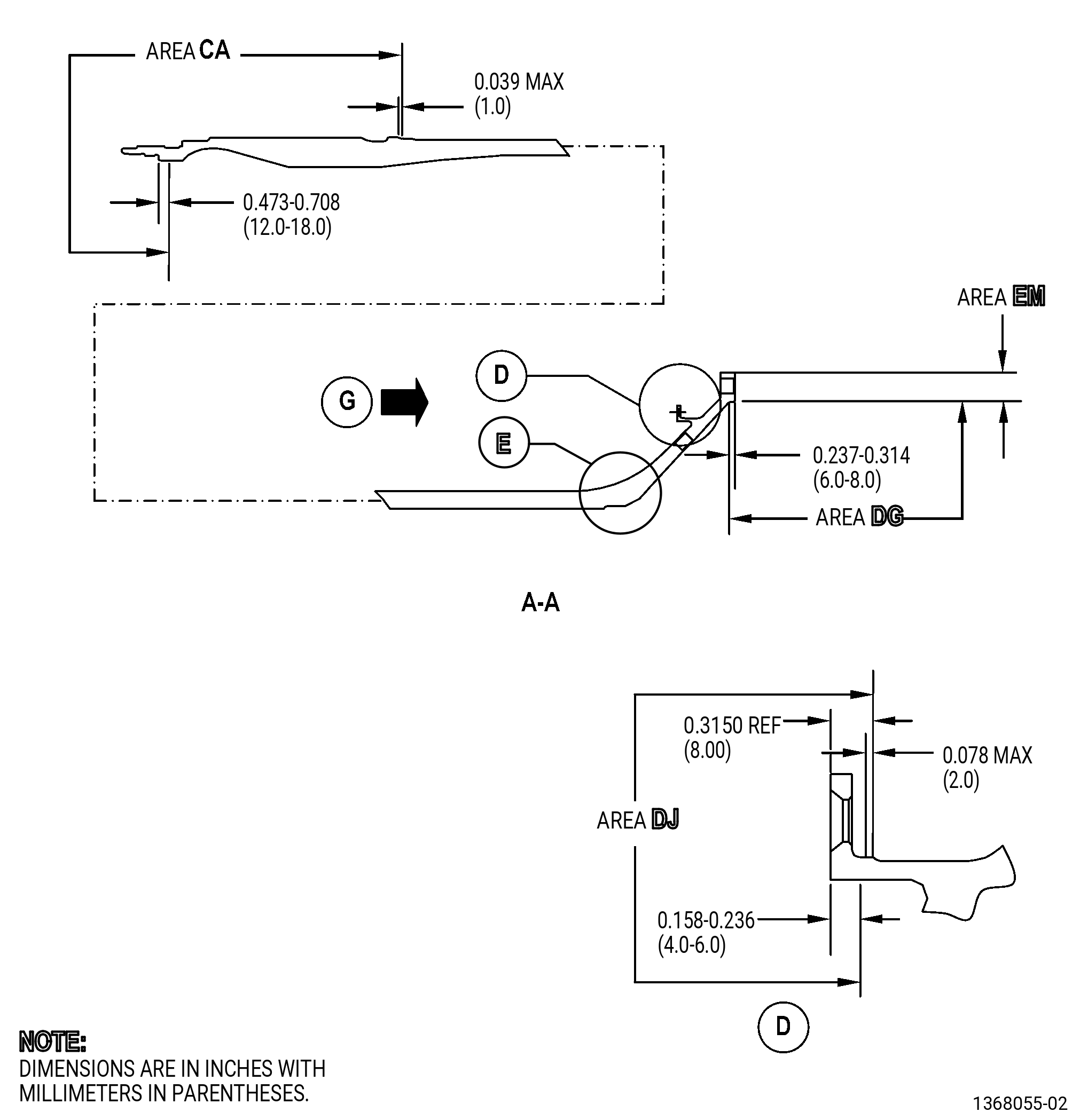
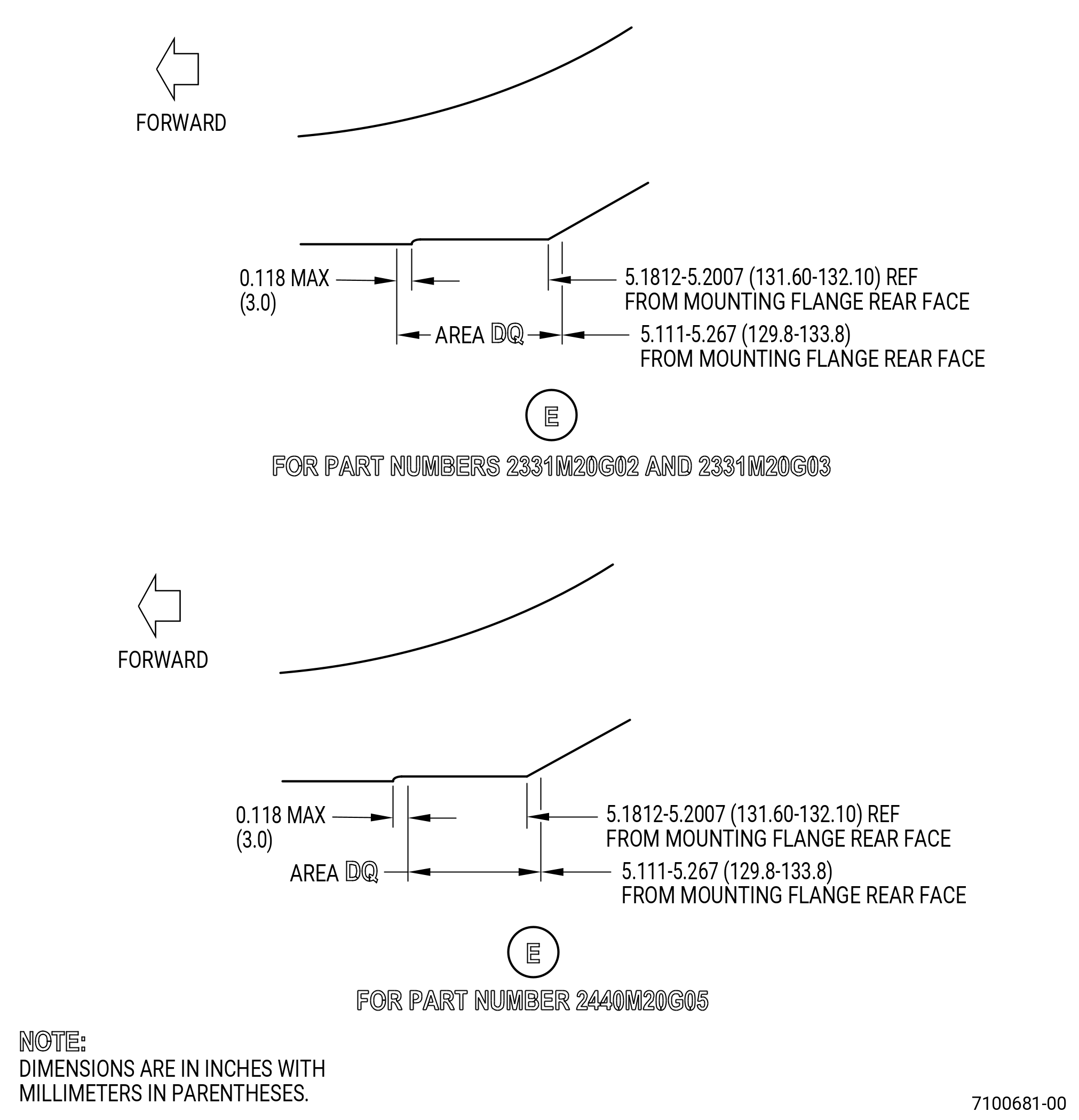
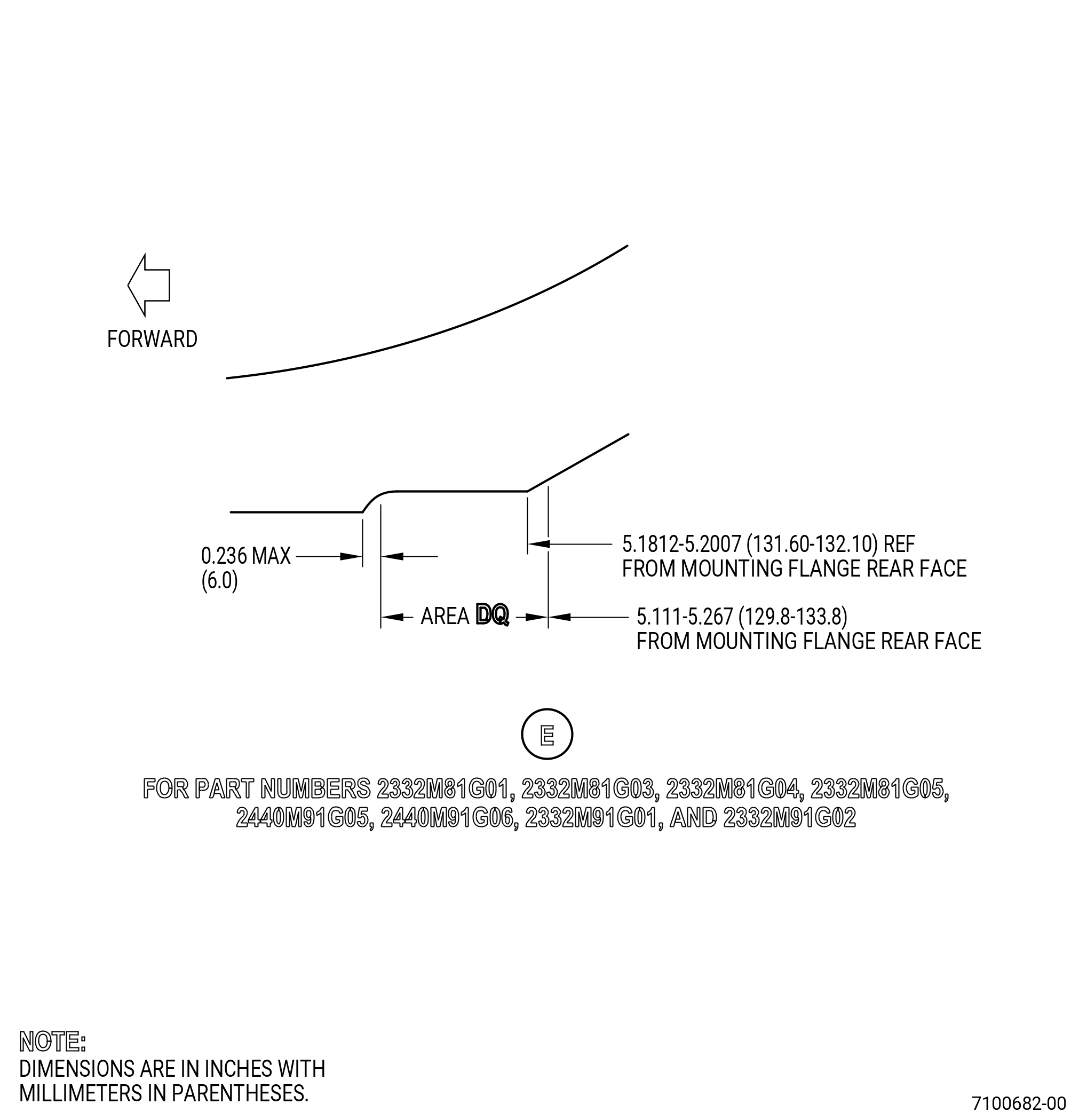
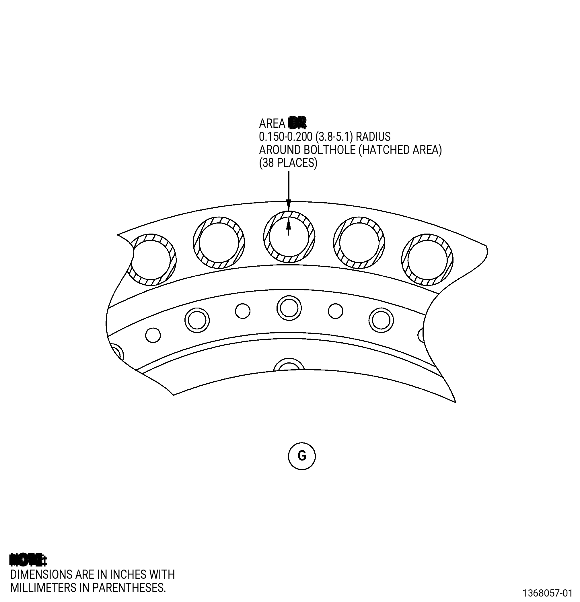
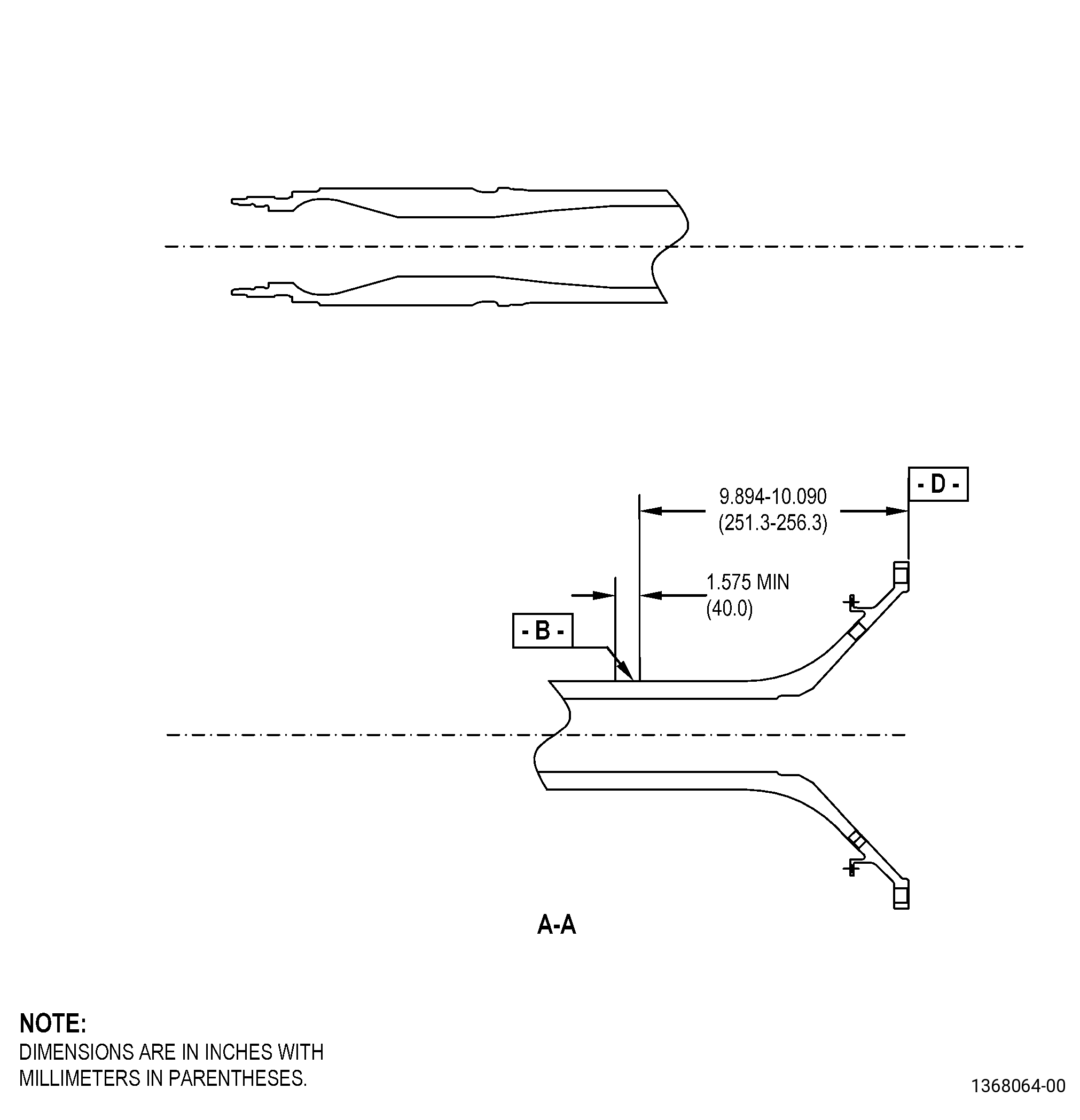
| A. | Refer to Figure 901 and Figure 902 for specified dimensions and locations. |
| NOTE: |
|
| NOTE: |
|
| 4 . | Setup Information. |
| None. |
| 5 . | Procedure |
| Subtask 72-58-40-100-004 |
| CAUTION: |
|
| A. | Remove the aluminum protective paint from the shaft. Refer to TASK 70-23-00-100-001 (STRIPPING PROCEDURES), TASK 70-23-02-110-019 (STRIPPING METHOD NO. 2 - STRIPPING INORGANIC BONDED ALUMINUM PAINT), and as follows: |
| (1) | If necessary, apply C10-021 plastic tape to adjacent surfaces where stripping is not necessary. |
| Subtask 72-58-40-300-004 |
| B. | Remove all the solid film lubricant from the shaft. Refer to TASK 72-58-40-300-804 (72-58-40, REPAIR 003). |
| Subtask 72-58-40-300-005 |
| C. | If necessary, remove the shank nuts from the shaft. Refer to TASK 72-58-40-300-802 (72-58-40, REPAIR 004). |
| Subtask 72-58-40-350-021 |
| D. | Make sure that you complete all the inspections and repairs necessary for the shaft before you continue with this procedure. |
| Subtask 72-58-40-100-005 |
| E. | If necessary, clean the shaft. Refer to TASK 70-21-00-110-051 (CHEMICAL CLEANING), and TASK 70-21-03-160-001 (CLEANING METHOD NO. 3 - STEAM CLEANING). |
| Subtask 72-58-40-380-006 |
| WARNING: |
|
| F. | Surface-treat the shaft. Refer to TASK 70-43-05-380-005 (INORGANIC ALUMINUM PROTECTIVE COATING), and as follows: |
| NOTE: |
|
| (1) | Apply C10-012 masking tape, C10-067 platers tape, or equivalent masking methods to area CA, area EM, area DG, area DQ, area DJ, area DR, datum B, and all the markings on the shaft. Refer to Figure 901 and Figure 902. |
| CAUTION: |
|
| (2) | Surface-treat the shaft to prepare the shaft surface for protective coating. Refer to TASK 70-43-05-380-005 (INORGANIC ALUMINUM PROTECTIVE COATING), and as follows: |
| (a) | Use C10-049 180 mesh grit. |
| (3) | Replace the masking, if necessary, after the shaft surface preparation. |
| (4) | Apply C03-038 sermetel paint or sermetel WFX-2 to all the shaft area. Do not include area CA, area EM, area DG, area DQ, area DJ, area DR, datum B, and all the markings on the shaft. |
| NOTE: |
|
| (5) | Make sure that you apply the paint to the shaft in a period of 2 hours after grit blast. |
| (6) | If necessary, replace masking between coats. |
| (7) | Bare metal, on the coating area of the shaft with aluminum protective paint, is not permitted. |
| Subtask 72-58-40-300-006 |
| G. | Apply solid film lubricant to the shaft. Refer to TASK 72-58-40-300-804 (72-58-40, REPAIR 003). |
| Subtask 72-58-40-640-003 |
| H. | Apply lubricant to the shaft shank nuts that you did not replace. Refer to TASK 70-43-09-640-001 (REPLACEMENT OF DRY-FILM LUBRICANT). |
| Subtask 72-58-40-300-007 |
| I. | If necessary, install the new shank nuts on the shaft. Refer to TASK 72-58-40-300-802 (72-58-40, REPAIR 004). |
| Subtask 72-58-40-300-008 |
| J. | Deleted. |
| Subtask 72-58-40-380-007 |
| K. | Surface-treat the shaft to touch-up the aluminum protective coating. Refer to TASK 70-43-05-380-005 (INORGANIC ALUMINUM PROTECTIVE COATING), and as follows: |
| (1) | Use only the C03-039 touch-up paint and the touch-up procedure. |
| (2) | If necessary, apply C10-021 plastic tape, C10-067 platers tape, or equivalent masking methods to adjacent surfaces where C03-039 touch-up paint is not necessary. |
| (3) | Prepare the shaft surface as described in TASK 70-43-05-380-005 (INORGANIC ALUMINUM PROTECTIVE COATING). |
| (4) | Apply the necessary thickness or number of coatings of C03-039 touch-up paint to the shaft areas that follows: |
| (a) | Datum B: three coats. |
| (b) | The protective paint areas of the shaft where touch-up is necessary: three coats. |
| (c) | All marking areas of the shaft: as thin as possible to let you read the markings. |
| (5) | Overlap with adjacent painted surfaces of the shaft is necessary. Bare metal is not permitted. |
| Subtask 72-58-40-550-001 |
| L. | If you will not assemble the shaft immediately, do the correct storage procedure to prevent corrosion in the shaft. Refer to TASK 72-58-00-550-801 (72-58-00, STORAGE 001). |